air condition MERCEDES-BENZ E-CLASS SALOON 2020 Owner's Manual
[x] Cancel search | Manufacturer: MERCEDES-BENZ, Model Year: 2020, Model line: E-CLASS SALOON, Model: MERCEDES-BENZ E-CLASS SALOON 2020Pages: 477, PDF Size: 8.67 MB
Page 214 of 477
R
The transmission is shif tedto position j.
R The vehicle is secured with the electric park‐
ing brake.
In thefo llowing situations, theve hicle is held by
transmission position jand/or bythe electric
parking brake:
R The seat belt is unfas tened and the driver's
door is opened.
R The vehicle is switched off.
R There is a malfunction in the sy stem or the
po we r supply is insuf ficient. DY
NA MIC BODY CONT ROL function DY
NA MIC BODY CONTROL continuously adjusts
th ech aracteristics of the suspension dampers to
th e cur rent operating and driving conditions.
The da mping is tuned individually for each wheel
and is af fected bythefo llowing factors:
R The road sur face conditions
R Vehicle load
R The drive program selected R
The driving style
The drive program can be adjus ted using the
DY NA MIC SELECT switch. AIR
BODY CONT ROL AIR
BODY CONT ROL function
* NO
TEMercedes-AMG vehicles #
Obser vethe no tes in the Supplement.
Yo u could otherwise failto recognise
dangers. AIR BODY
CONTROL is an air suspension sy stem
with variable damping for impr oved driving com‐
fo rt. The all-round le vel control sy stem ensures
th e best possible suspension and const ant
ground clearance, even wi tha laden vehicle.
When driving at speed, theve hicle is lo wered
automatically toimpr ovedriving saf ety and to
re duce fuel consum ption. You also ha vethe
option of manually adjusting theve hicle le vel. AIR
BODY CONTROL includes thefo llowing com‐
ponents and functions:
R Air suspension with variable spring rate
R Automatic le vel control sy stem
R Speed-dependent lo wering toreduce fuel
consum ption
R Manually selec table high-le vel setting for
grea ter ground clea rance
R ADS PLUS (Ada ptive Damping Sy stem with
const ant damping forc e adjustment)
R DYNA MIC SELECT switch and le vel button
Suspension settings and vehicle le vel per
drive prog ram
Drive program A:
R The suspension setting is comfor table.
R The vehicle is set tothe normal le vel.
R When driving at speeds of appr oximately
12 5 km/h or abo ve,th eve hicle is lo wered.
R When driving at speeds below appr oximately
80 km/h, theve hicle is raised again. Driving and parking
211
Page 215 of 477
Drive program
;:
R The suspension setting is comfor table.
R The vehicle is set tolow le vel -1.
R The vehicle is not lo wered any fur ther if you
are tra velling at higher speeds.
Drive program C:
R The suspension setting is firm er.
R The vehicle is set tolow le vel -1.
R The vehicle is not lo wered any fur ther if you
are tr avelling at higher speeds.
Drive prog ram B:
R The suspension setting is evenfirm er.
R The vehicle is set tolow le vel -1.
R The vehicle is not lo wered any fur ther if you
are tr avelling at higher speeds.
Individual suspension settings can be called up
in drive prog ram = (/page 167). Setting
theve hicle le vel &
WARNING Risk of accident because
ve hicle le vel is too high
Driving characteristics may be impaired.
The vehicle can drift outwards, forex ample,
when steering or cornering. #
Choose a vehicle le vel which is suited
to the driving style and thero ad sur face
conditions. &
WARNING Risk of entrapment from vehi‐
cle lo wering
When lo wering theve hicle, other people
could become trapped if their limbs are
between theve hicle body and the tyres or
underneath theve hicle. #
Make sure no one is underneath the
ve hicle or in the immediate vicinity of
th e wheel ar ches when theve hicle is
being lo wered. &
WARNING Risk of becoming trapped
due totheve hicle lo wering
Ve hicles with AIR BODY CONT ROL or
le ve l control sy stem: when you unload lug‐
ga ge or lea vetheve hicle, theve hicle first
ri ses slightly and then returns tothe set le vel
shortly af terw ards.
Yo u or an yone else in the vicinity of the
wheel ar ches or the underbody could thus
become trapped.
The vehicle can also be lo wered af ter being
loc ked. #
When leaving theve hicle, make sure
th at nobody is in the vicinity of the
wheel ar ches or the underbody. *
NO
TEDama gedue tovehicle lo wering Pa
rts of the body could be damaged when
th eve hicle is lo wered. #
Make sure that there are no obs tacles
such as kerbs underneath or in the212
Driving and pa rking
Page 223 of 477
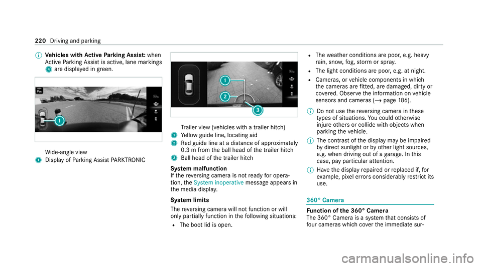
%
Vehicles with Active Parking Assis t:when
Ac tive Parking Assist is active, lane markings
4 are displa yed in green. Wi
de-angle view
1 Display of Parking Assist PARKTRONIC Tr
ailer view (vehicles with a trailer hit ch)
1 Yellow guide line, locating aid
2 Red guide line at a dis tance of appr oximately
0.3 m from the ball head of the trailer hitch
3 Ball head of the trailer hitch
Sy stem malfunction
If th ere ve rsing camera is not ready for opera‐
tion, theSystem inoperative message appears in
th e media displa y.
Sy stem limits
The reve rsing camera will not function or will
only partially function in thefo llowing situations:
R The boot lid is open. R
The weather conditions are poor, e.g. heavy
ra in, sno w,fog, storm or spr ay.
R The light conditions are poor, e.g. at night.
R Cameras, or vehicle components in which
th e cameras are fitted, are dama ged, dirty or
co vered. Obser vethe information on vehicle
sensors and cameras (/ page186).
% Do not use there ve rsing camera in these
types of situations. You could otherwise
injure others or collide with objects when
parking theve hicle.
% The contra stof the display may be impaired
by direct sunlight or by other light sources,
e.g. when driving out of a garage . In this
case, pay particular attention.
% Have the display repaired or replaced if, for
ex ample, pixel er rors considerably restrict its
use. 360° Came
ra Fu
nction of the 360° Camera
The 360° Camera is a sy stem that consists of
fo ur cameras which co verth e immediate sur‐ 220
Driving and parking
Page 227 of 477
R
The weather conditions are poor, e.g. heavy
ra in, sno w,fog, storm or spr ay.
R The light conditions are poor, e.g. at night.
R The camera lens is obstructed, dirty or mis‐
ted up.
R If cameras or vehicle components in which
th e cameras are fitted are dama ged. In this
eve nt, ha vethe cameras, their positions and
th eir setting checked at a qualified specialist
wo rkshop.
% Do not use the 360° Camera under such cir‐
cums tances. You could otherwise injure oth‐
ers or collide with objects when parking the
ve hicle.
Fo rte ch nical reasons, thest andard height of the
ve hicle may be altered if theve hicle is car rying a
heavy load and can result in inaccuracies in the
guide lines and in the display of thege nerated
ima ges.
The field of vision and other functions of the
came rasystem may be restricted due toaddi‐
tional attachments on theve hicle (e.g. licence
plate brac ket, bicycle rack ). %
The contrast of the display may be impaired
by abrupt, direct sunlight or by other light
sources, e.g. when driving out of a garage . In
th is case, pay particular attention.
% Have the display repaired or replaced if, for
ex ample, pixel er rors considerably restrict its
use.
See the no tes on cleaning the 360° Camera
(/ page 310).
Calling up the view of the 360° Camera
using reve rsege ar
Re quirements:
R The Auto reversing camera function is activa‐
te d in the multimedia sy stem (/ page 224). #
Shift toreve rsege ar. #
Select the desired view in the multimedia
sy stem (/ page 220). #
If, af ter shifting toreve rsege ar, the image of
th ere ve rsing camera is not shown: switch off
th e ignition, press and hold thec button,
switch on the ignition and engage reve rse
ge ar again. Swit
ching reve rsing camera automatic mode
on/off
The reve rsing camera is only an aid. It is not a
substitute foryo ur attention tothe sur roundings.
The responsibility for safe manoeuvring and
parking remains with you. Make sure that no
persons, animals or objects etc. are in the
manoeuvring range. Pay attention to your sur‐
ro undings and be ready tobrake at all times.
Multimedia sy stem:
4 © 5
Settings 5
Assistance
5 Camera & parking #
Switch Auto reversing camera on or off. Ac
tive Parking Assist Fu
nction of Active Parking Assist
Ac tive Parking Assist is an elect ronic pa rking
assis tance sy stem, which uses ultrasound with
th e assis tance of there ve rsing camera and 360°
Camera. When you are driving forw ards up to
appr oximately 35 km/h, the sy stem automati‐
cally measures parking spaces on bo thsides of
th eve hicle. 224
Driving and parking
Page 236 of 477
Sy
stem limits
The sy stem may be impaired or may not function
particular lyin thefo llowing situations:
R Ifth ere is poor visibility, e.g. due toinsuf fi‐
cient illumination of thero ad, if there are
highly variable shade conditions or in rain,
sno w,fog or heavy spr ay.
R Ifth ere is glare, e.g. from oncoming traf fic,
di re ct sunlight or reflections.
R Ifth e windscreen in the area of the multi‐
function camera is dirty, or if the camera is
mis ted up, damaged or co vered.
R Ifth e tra ffic signs are hard todetect, e.g. due
to dirt or sno w,because they are co vered, or
due toinsuf ficient lighting.
R Ifth e information in the navigation sy stem's
digital map is incor rect or out-of-da te.
R Ifth e signs are ambiguous, e.g. tra ffic signs
on con stru ction sites or in adjacent lanes.
R Ifyo u turn sharply when passing traf fic signs
outside the camera's field of vision.
Setting Traf fic Sign Assist
Re quirements: R
Only vehicles with Driving Assistance
Pa ckage:
Ac tive Dis tance Assi stDISTRONIC mu stbe
activated forth e automatic adoption of
speed limits.
Multimedia sy stem:
4 © 5
Settings 5
Assistance
5 Traffic Sign Assist
Ac tivating or deactivating automatic adop‐
tion of speed limits (only vehicles with Driv‐
ing Assistance Package) #
Select Adopt limit. #
Activate or deacti vate the function.
The speed limits de tected byTraf fic Sign
Assi stare automatically adop tedby Active
Dis tance Assi stDISTRONIC.
% If one of thefo llowing sy stems is activated,
th e de tected speed can be manually adop ted
as the speed limit:
R Active Dis tance Assi stDISTRONIC
R Cruise control
R Variable limiter Fu
rther information (/ page 202).
Displaying de tected traf fic signs in the
medi a display #
Select Display in head unit. #
Activate or deacti vate the function.
Setting the type of warning #
Select Visual & audible ,Visual orOff .
Setting thewa rning threshold
This value de term ines the speed at which a
wa rning is issued when exceeded. #
Select Warning threshold. #
Set the desired speed. Blind Spot Assist and
Active Blind Spot
Assi stwith exitwa rning Fu
nction of Blind Spot Assist and Active
Blind Spot Assi stwith exitwa rning
Blind Spot Assist and Active Blind Spot Assi st
use two lateral, rear-facing radar sensors to
monitor the area up to40 m behind and 3 m
next toyour vehicle. Driving and parking
233
Page 241 of 477
Conditions
for a course-cor recting brake
application (vehicles with Driving Assistance
Pa ckage)
Depending on the setting, a course cor recting
brake application occu rsinthefo llowing situa‐
tions (/ page 239).
% The availability of this setting is dependent
on the count ry. If the function is activated in
count ries in which this setting is notavaila‐
ble, a lane-cor recting brake application is ini‐
tia ted in all situations described under Sen-
sitive.
Standard Setting
R A lane marking and an approaching vehicle,
an ove rtaking vehicle or vehicles driving par‐
allel to yo urvehicle weredetected in the
adjacent lane. The front wheel drives over
th e lane marking.
Sensitive Setting
R The situations described under theStandard
setting.
R A continuous lane marking was de tected and
driven over with the front wheel. %
A brake application may be inter rupte d at
any time if yousteer slightly in the opposite
direction.
Sy stem limits
No lane-cor recting brake application occu rsin
th efo llowing situations:
R You clear lyand actively steer, brake or accel‐
erate.
R If a driving saf ety sy stem inter venes, su chas
ESP ®
,Ac tive Brake Assi stor Active Blind
Spot Assi st.
R You ha veadop ted a sporty driving style with
high cornering speeds or high rates of accel‐
eration.
R When ESP ®
is deactivated.
R When driving with a trailer, the electrical con‐
nection tothe trailer has been cor rectly
es tablished.
R If a loss of tyre pressure or a defective tyre
has been de tected and displ ayed.
If yo u deactivate theAc tive Lane Keeping Assist
wa rning and the lane markings cann otbe clearly de
tected, it is possible that no lane cor recting
brake application take s place (/ page 239).
The sy stem may be impaired or may not function
particular lyin thefo llowing situations:
R Ifth ere is poor visibility, e.g. due toinsuf fi‐
cient illumination of thero ad, if there are
highly variable shade conditions or in rain,
sno w,fog or heavy spr ay.
R Ifth ere is glare, e.g. from oncoming traf fic,
th e sun or reflections.
R Ifth e windscreen in the area of the multi‐
function camera is dirty, or if the camera is
mis ted up, damaged or co vered.
R Ifth ere are no lane markings, or se veral
unclear lane markings are present for one
lane, e.g. around roadwor ks.
R Ifth e lane markings are worn, dark or cov‐
ered.
R Ifth e dis tance from theve hicle in front is too
short and thus the lane markings cann otbe
de tected. 238
Driving and pa rking
Page 246 of 477
R
Drive AwayAssi st
R Cross Traf fic Alert
R Reversing camera
R 360° camera
R AIR BODY CONTROL
Coupling up a trailer
* NO
TEDama getothest ar ter battery due
to full discharge Charging
the trailer battery using the po wer
supply of the trailer can damage thest ar ter
batter y. #
Do not use theve hicle's po wer supply
to charge the trailer batter y. #
Remo vethe co ver cap from the ball head and
st ore it in a safe place (/ page111). #
Position the trailer on a le vel sur face behind
th eve hicle and couple it up totheve hicle. #
Open the soc ket cap. #
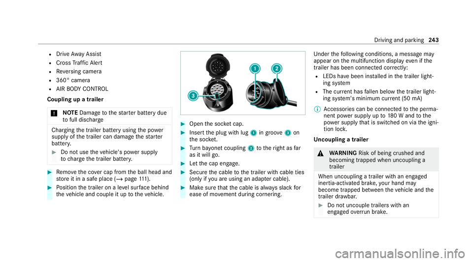
Inse rtthe plug with lug 1in groo ve3 on
th e soc ket. #
Turn bayonet coupling 2totheright as far
as it will go. #
Let the cap engage. #
Secure the cable tothe trailer with cable ties
(only if you are using an adap ter cable). #
Make sure that the cable is alw ays slack for
ease of mo vement during cornering. Under
thefo llowing conditions, a message may
appear on the multifunction display even if the
trailer has been connected cor rectly:
R LEDs ha vebeen ins talled in the trailer light‐
ing sy stem
R The cur rent has fallen below the trailer light‐
ing sy stem's minimum cur rent (50 mA)
% Accessories can be connected tothe perma‐
nent po wer supp lyup to180 W and tothe
po we r supp lythat is swit ched on via the igni‐
tion loc k.
Un coupling a trailer &
WARNING Risk of being crushed and
becoming trapped when uncoupling a
trailer
When uncoupling a trailer wi than engaged
ine rtia-activated brake, your hand may
become trapped between theve hicle and the
trailer dr awbar. #
Do not uncouple trailers with an
engaged overrun brake. Driving and pa
rking 243
Page 251 of 477
Note
s onthe instrument display and on-
board compu ter &
WARNING Risk of accident due toan
instrument display malfunction
If th e instrument display has failed or mal‐
functioned, the function restrictions applying
to saf etyre leva nt sy stems are not visible.
The operating saf ety of your vehicle may be
impaired. #
Drive on carefull y.#
Have theve hicle checked immediately
at a qualified specialist workshop. &
WARNING Risk of di stra ction from infor‐
mation sy stems and communications
equipment
If yo u operate information and communica‐
tion equipment integ rated in theve hicle
when driving, you will be distracted from the
traf fic situation. This could also cause youto
lose control of theve hicle. #
Only operate this equipment when the
traf fic situation permits. #
Ifyo u cannot be sure of this, stop the
ve hicle whilst paying attention toroad
and traf fic conditions and ope rate the
equipment with theve hicle stationar y. *
NO
TEMercedes-AMG vehicles #
Obser vethe no tes in the Supplement.
Yo u could otherwise failto recognise
dangers. *
NO
TEPlug-in hybrid #
Obser vethe no tes in the Supplement.
Yo u could otherwise failto recognise
dangers. Yo
u must obse rveth e legal requirements forthe
country in whi chyou are cur rently driving when
operating the on-board computer.
The on-board computer sho wsonly display mes‐
sages and warnings from specific sy stems on th
e multifunction displa y.Yo u must therefore
ensure that your vehicle is alw aysre liable.
If th e operating saf ety of your vehicle is
impaired, park theve hicle immediately and
safel y.Con tact a qualified specialist workshop. 248
Instrument display and on-board computer
Page 260 of 477
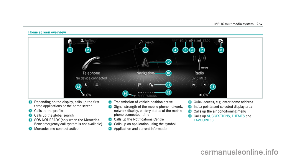
Home screen
overview 1
Depending on the displa y,calls up thefirst
th re e applications or the home screen
2 Calls up the profile
3 Calls up theglobal sear ch
4 SOS NOT READY (only when the Mercedes-
Benz emer gency call sy stem is not available)
5 Mercedes me connect active 6
Transmission of vehicle position active
7 Signal stre ngth of the mobile phone networ k,
network displ ay, battery status of the mobile
phone connected, time
8 Calls up the Notifications Centre
9 Calls up an application using the symbol
A Application and cur rent information B
Quick-access, e.g. enter home address
C Index points and selected displ ayarea
D Calls up the air conditioning menu
E Calls up SUGGESTIONS, THEMESand
FAVOURITES MBUX multimedia sy
stem 257
Page 264 of 477
Overview of
the MBUX Interior Assistant &
WARNING Risk of inju ryfrom the cam‐
era's laser radiation
This product uses a classification 1 laser sys‐
te m. If the housing is opened or damaged,
laser radiation may damage your retina. #
Do not open the housing. #
Alw ays ha vemaintenance workand
re pairs car ried out byaqu alified spe‐
cialist workshop. This device is a class 1 laser product in accord‐
ance with DIN EN 60825-1:20
14
The camera is located in theove rhead control
panel.
If th eve hicle is fitted wi th the MBUX Interior
Assis tant, selected functions of the multimedia sy
stem can be operated conta ct-free. The MBUX
Interior Assi stant can dif fere ntia tebetween
driver and front passenger interactions and
de tects specific hand positions (poses).
Sy stem limits, display messages and no tes
fo rre ctification
The sy stem may be impaired or may not function
in thefo llowing situations:
R The camera in theove rhead control panel
may heat up due tooperating conditions. As
a re sult the camera may switch off temp ora‐
ri ly , particular lyduring longer periods of
operation and at high outside temp eratures.
Do not touch or co verth e camera and wait
until the camera has cooled down and is
av ailable again. R
The camera is co vered or dirty, mis ted up or
scratched.
Wa it until the camera has cooled down
before cleaning the camera lens.
Clean the outside of the camera lens with a
dry or damp cotton clo th. Do not use microfi‐
bre clo ths. Do notremo vethe co ver when
cleaning.
R Recognition can be impaired byreflective
clo thing, an adverse colour of clo thing or by
accesso ries, forex ample.
R Clothing being worn(hat, shawl, scarf) may
be limiting the de tection area of the camera.
Ke ep the camera's field of vision clear.
R The camera is not operational.
Consult a Mercedes-Benz service cent re. MBUX multimedia sy
stem 261