MERCEDES-BENZ EQC SUV 2021 Owners Manual
Manufacturer: MERCEDES-BENZ, Model Year: 2021, Model line: EQC SUV, Model: MERCEDES-BENZ EQC SUV 2021Pages: 453, PDF Size: 8.68 MB
Page 181 of 453
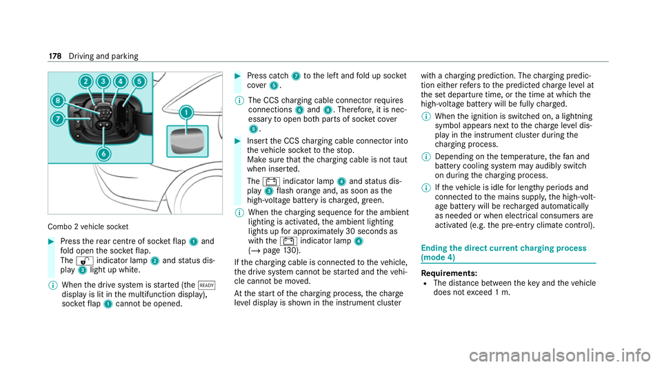
Combo 2
vehicle soc ket #
Press there ar centre of soc ketflap 1 and
fo ld open the soc ketflap.
The % indicator lamp 2and status dis‐
play 3light up white.
% When the drive sy stem is star ted (the õ
display is lit in the multifunction display),
soc ketflap 1 cannot be opened. #
Press cat ch7 tothe left and fold up soc ket
co ver5.
% The CCS charging cable connec torre qu ires
connections 6and 8. Therefore, it is nec‐
essary toopen bo thparts of soc ket co ver
5 . #
Insert the CCS charging cable connec tor into
th eve hicle soc ketto thestop.
Make sure that thech arging cable is not taut
when inser ted.
The # indicator lamp 4and status dis‐
play 3flash orange and, as soon as the
high-voltage battery is charge d, green.
% When thech arging sequence forth e ambient
lighting is activated, the ambient lighting
lights up for appro ximately 30 seconds as
with the# indicator lamp 4
(/ page 130).
If th ech arging cable is connec tedto theve hicle,
th e drive sy stem cann otbe star ted and theve hi‐
cle cannot be mo ved.
At thest art of thech arging process, thech arge
le ve l display is shown in the instrument clus terwith a
charging prediction. The charging predic‐
tion either refers to the predicted charge leve l at
th e set departure time, or the time at which the
high-voltage battery will be fully charge d.
% When the ignition is switched on, a lightning
symbol appears next tothech arge leve l dis‐
play in the instrument clus ter during the
ch arging process.
% Depending on thete mp erature, thefa n and
battery cooling sy stem may audibly switch
on during thech arging process.
% Ifth eve hicle is idle for lengt hyperiods and
connec tedto the mains suppl y,the high-volt‐
age battery will be rech arge d automatically
as needed or when elect rical consumers are
acti vated (e.g. the pre-entry climate control). Ending
the direct cur rent charging process
(mode 4) Re
quirements:
R The dis tance between theke y and theve hicle
does not exceed 1 m. 17 8
Driving and pa rking
Page 182 of 453
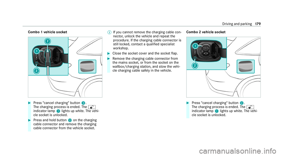
Combo 1
vehicle soc ket #
Press "cancel charging" button 3.
The charging process is ended. The %
indicator lamp 1lights up white. The vehi‐
cle soc ket is unloc ked. #
Press and hold button 2onthech arging
cable connec tor and remo vethech arging
cable connec tor from theve hicle soc ket. %
Ifyo u cannot remo vethech arging cable con‐
nec tor,unlo cktheve hicle and repeat the
procedure. If thech arging cable connec tor is
st ill loc ked, con tact a qualified specialist
wo rkshop. #
Close the soc ket co ver and the soc ketflap. #
Remo vethech arging cable connec tor from
th e mains soc ket, or from the soc ket on the
wa llbox/ charging station, and stow theve hi‐
cle charging cable safely in theve hicle. Combo 2
vehicle soc ket #
Press "cancel charging" button 2.
The charging process is ended. The %
indicator lamp 1lights up white. The vehi‐
cle soc ket is unloc ked. Driving and parking
17 9
Page 183 of 453
%
Ifyo u cannot remo vethech arging cable con‐
nec tor,unlo cktheve hicle and repeat the
procedure. If thech arging cable connec tor is
st ill loc ked, con tact a qualified specialist
wo rkshop. #
Close the soc ket co ver and the soc ketflap. #
Remo vethech arging cable connec tor from
th e mains soc ket, or from the soc ket on the
wa llbox/ charging station, and stow theve hi‐
cle charging cable safely in theve hicle.
% Afterth ech arging cable connec tor has been
disconnected, the left % indicator lamp
1 ontheve hicle soc ketre mains lit for
some time before switching off. Fu
nction of thech arge leve l display in the
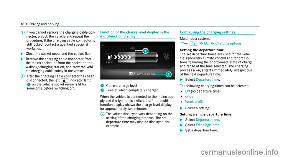
mu ltifunction display 1
Current charge level
2 Time at which comple tely ch arged
When theve hicle is connected tothe mains sup‐
ply and the ignition is switched off, the multi‐
function display sho ws thech arge leve l display
fo r appro ximately two minutes.
% The values displa yedva ry depending on the
setting of thech arging process. The set
departure time may also be displa yed, for
ex ample. Configuring
thech arging settings Multimedia sy
stem:
4 © 5
EQ 5
Charging options
Setting the departu retime
The set depa rture times are used forth eve hi‐
cle's pre-entry climate control and for predic‐
tions rega rding the appr oximate state of charge
and range at the time selected. The charging
process alw aysst arts immediatel y,irre spective
of the next departure time. #
Select Departure time.
The following charging times can be selec ted:
R Off (no departure time)
R Once
R Week profile #
Select a setting.
Setting a single depa rture time #
Select Departure time . #
Select Edit single time . #
Set a depa rture time. 18 0
Driving and pa rking
Page 184 of 453
Setting
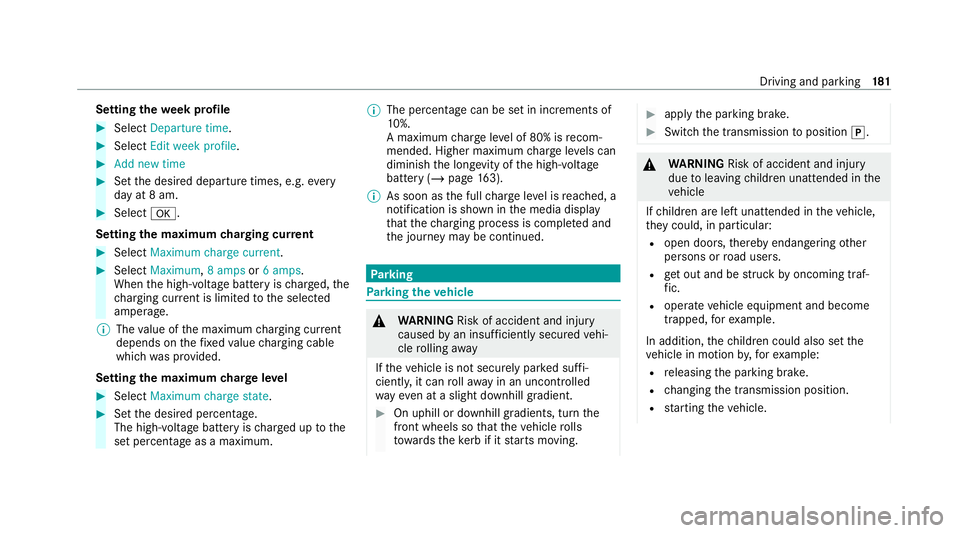
thewe ek profile #
Select Departure time. #
Select Edit week profile. #
Add new time #
Set the desired departure times, e.g. every
day at 8 am. #
Select a.
Setting the maximum charging cur rent #
Select Maximum charge current. #
Select Maximum, 8 ampsor6 amps .
When the high-voltage battery is charge d, the
ch arging cur rent is limited tothe selected
amperage.
% The value of the maximum charging cur rent
depends on thefixe dva lue charging cable
which was pr ovided.
Setting the maximum charge level #
Select Maximum charge state .#
Set the desired percentage.
The high-voltage battery is charge d up tothe
set percentage as a maximum. %
The percenta gecan be set in increments of
10 %.
A maximum charge leve l of 80% is recom‐
mended. Higher maximum charge leve ls can
diminish the long evity of the high-voltage
battery (/ page163).
% As soon as the full charge leve l is reached, a
notification is shown in the media display
th at thech arging process is comple ted and
th e journey may be continued. Pa
rking Pa
rking theve hicle &
WARNING Risk of accident and inju ry
caused byan insuf ficiently secu redve hi‐
cle rolling away
If th eve hicle is not securely par ked suf fi‐
ciently, it can rollaw ay in an uncont rolled
wa yev en at a slight downhill gradient. #
On uphill or downhill gradients, turn the
front wheels so that theve hicle rolls
to wa rdsth eke rb if it starts moving. #
apply the parking brake. #
Switch the transmission toposition j. &
WARNING Risk of accident and inju ry
due toleaving children unat tended in the
ve hicle
If ch ildren are left unat tended in theve hicle,
th ey could, in pa rticular:
R open doors, thereby endangering other
persons or road users.
R get out and be stru ck byoncoming traf‐
fi c.
R ope rate ve hicle equipment and become
trapped, forex ample.
In addition, thech ildren could also set the
ve hicle in motion by,fo rex ample:
R releasing the parking brake.
R changing the transmission position.
R starting theve hicle. Driving and parking
181
Page 185 of 453
#
Never lea vechildren unat tended in the
ve hicle. #
When leaving theve hicle, alw aysta ke
th eke y with you and lock theve hicle. #
Keep theve hicle key out of there ach of
ch ildren. *
NO
TEDama getotheve hicle due toit
ro lling away #
Alw ays secure theve hicle against roll‐
ing away. *
NO
TEDama gedue totheve hicle lo wer‐
ing The
vehicle can lo wer because of temp era‐
ture dif fere nces or longer non-operational
times. This can cause dama getoparts of the
body. #
When stopping theve hicle and when
driving off, make sure that there are no
obs tacles su chas curbs under or in the
immediate vicinity of the body. %
Ifyo u park theve hicle for a long period,
obser vethefo llowing no tes:
R Make sure the high-voltage battery has a
suf ficient state of charge , especially at
ve ry low outside temp eratures. In this
wa yyo u can avoid any problems when
th e drive sy stem is subsequently star ted.
R If possible, avoid parking spaces in direct
sunlight.
Obser vethe no tes on charging the high-volt‐
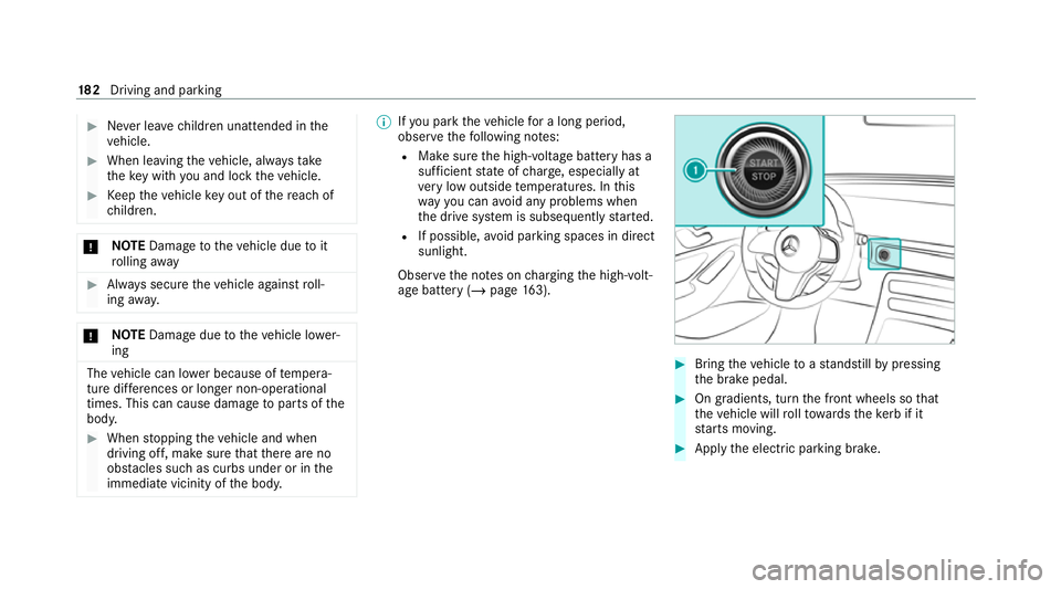
age battery (/ page163). #
Bring theve hicle toast andstill bypressing
th e brake pedal. #
On gradients, turn the front wheels so that
th eve hicle will rollto wa rdsth eke rb if it
st arts moving. #
App lythe electric parking brake. 18 2
Driving and pa rking
Page 186 of 453
#
Engage transmission position jin a station‐
ary vehicle with the brake pedal applied
(/ page 162). #
Switch off the drive sy stem bypressing the
1 button. #
Release the service brake slowl y.#
Get out of theve hicle and lock it.
% When you park theve hicle, you can still
opera tethe side windo wsand the sliding
sunroof for appro ximately four minutes if the
driver's door is closed. Garage door opener
Prog
ramming buttons for the garage door
opener &
WARNING Risk of inju rywhen opening
or closing a door with thega rage door
opener
When you operate or program the door with
th e integrated garage door opener, persons
in thera nge of mo vement of the door may
become trapped or be stru ck bythe door. #
Alw ays make sure that nobody is within
th era nge of mo vement of the door. Re
quirements:
R The vehicle has been par ked outside the
ga rage or outside thera nge of mo vement of
th e door.
R The drive sy stem has been switched off.
R The ignition is switched on.
% The garage door opener function is alw ays
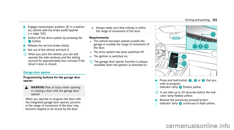
av ailable when the ignition is switched on. #
Press and hold button 1,2or3 that you
wish toprog ram.
Indicator lamp 4flashes yello w.
% It can take up to20 seconds before the indi‐
cator lamp flashes yello w. #
Release the pr eviously pressed button.
Indicator lamp 4continues toflash yello w. Driving and pa
rking 18 3
Page 187 of 453
#
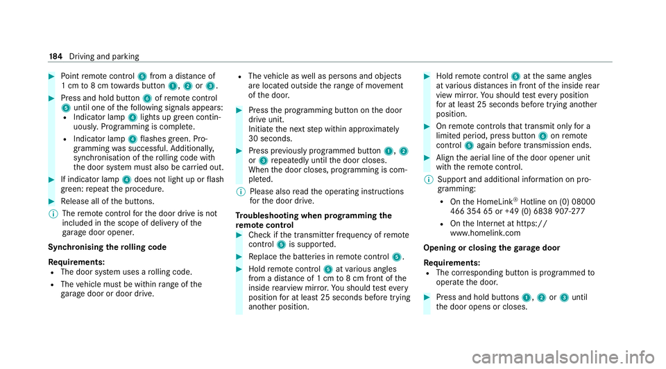
Point remo tecontrol 5from a di stance of
1 cm to8 cm towa rds button 1,2or3. #
Press and hold button 6ofremo tecontrol
5 until one of thefo llowing signals appears:
R Indicator lamp 4lights up green contin‐
uousl y.Programming is comple te.
R Indicator lamp 4flashes green. Pro‐
gramming was successful. Additionall y,
synchronisation of thero lling code with
th e door sy stem must also be car ried out. #
If indicator lamp 4does not light up or flash
green: repeat the procedure. #
Release all of the buttons.
% The remo tecontrol forth e door drive is not
included in the scope of delivery of the
ga rage door opener.
Synchronising thero lling code
Re quirements:
R The door sy stem uses a rolling code.
R The vehicle must be within range of the
ga rage door or door drive. R
The vehicle as well as persons and objects
are located outside thera nge of mo vement
of the door. #
Press the programming button on the door
drive unit.
Initiate the next step within appr oximately
30 seconds. #
Press pr eviously prog rammed button 1,2
or 3 repeatedly until the door closes.
When the door closes, programming is com‐
ple ted.
% Please also read the operating instructions
fo rth e door drive.
Tr oubleshooting when prog ramming the
re mo tecont rol #
Check if the transmit ter frequency of remo te
control 5is suppo rted. #
Replace the batteries in remo tecontrol 5. #
Hold remo tecontrol 5atvarious angles
from a dis tance of 1 cm to8 cm front of the
inside rearview mir ror.Yo u should test eve ry
position for at least 25 seconds before trying
ano ther position. #
Hold remo tecontrol 5atthe same angles
at various dis tances in front of the inside rear
view mir ror.Yo u should test eve ryposition
fo r at least 25 seconds before trying ano ther
position. #
Onremo tecontrols that transmit on lyfor a
limi ted period, press button 6onremo te
control 5again before transmission ends. #
Align the aerial line of the door opener unit
with there mo tecontrol.
% Support and additional information on pro‐
gramming:
R Onthe HomeLink ®
Hotline on (0) 08000
466 354 65 or +49 (0) 6838 907-2 77
R Onthe Internet at https://
www.homelin k.com
Opening or closing the garage door
Requ irements:
R The cor responding button is programmed to
operate the door. #
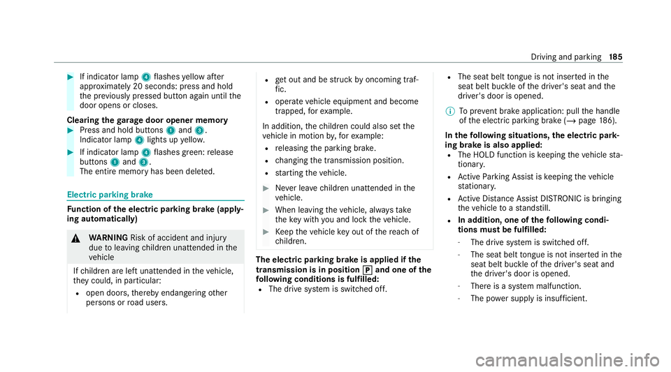
Press and hold buttons 1,2or3 until
th e door opens or closes. 184
Driving and pa rking
Page 188 of 453
#
If indicator lamp 4flashes yellow af ter
appr oximately 20 seconds: press and hold
th e pr eviously pressed button again until the
door opens or closes.
Clearing thega rage door opener memo ry#
Press and hold buttons 1and 3.
Indicator lamp 4lights up yello w. #
If indicator lamp 4flashes green: release
buttons 1and 3.
The entire memo ryhas been dele ted. Electric parking brake
Fu
nction of the electric pa rking brake (app ly‐
ing automatically) &
WARNING Risk of accident and inju ry
due toleaving children unat tended in the
ve hicle
If ch ildren are left unat tended in theve hicle,
th ey could, in pa rticular:
R open doors, thereby endangering other
persons or road users. R
get out and be stru ck byoncoming traf‐
fi c.
R ope rate ve hicle equipment and become
trapped, forex ample.
In addition, thech ildren could also set the
ve hicle in motion by,fo rex ample:
R releasing the parking brake.
R changing the transmission position.
R starting theve hicle. #
Never lea vechildren unat tended in the
ve hicle. #
When leaving theve hicle, alw aysta ke
th eke y with you and lock theve hicle. #
Keep theve hicle key out of there ach of
ch ildren. The electric pa
rking brake is applied if the
tr ansmission is in position j
jand one of the
fo llowing conditions is fulfilled:
R The drive sy stem is switched off. R
The seat belt tongue is not inser ted in the
seat belt buckle of the driver's seat and the
driver's door is opened.
% Toprev ent brake application: pull the handle
of the electric parking brake (/ page186).
In thefo llowing situations, the electric pa rk‐
ing brake is also applied:
R The HOLD function is keeping theve hicle sta‐
tionar y.
R Active Parking Assist is keeping theve hicle
st ationar y.
R Active Dis tance Assi stDISTRONIC is bringing
th eve hicle toast andstill.
R In addition, one of thefo llowing condi‐
tions mu stbe fulfilled:
- The drive sy stem is switched off.
- The seat belt tongue is not inser ted in the
seat belt buckle of the driver's seat and
th e driver's door is opened.
- There is a sy stem malfunction.
- The po wer supp lyis insuf ficient. Driving and pa
rking 18 5
Page 189 of 453
-
The vehicle is stationary for a lengt hy
period.
When the electric parking brake is applied, the
re d! indicator lamp lights up in the instru‐
ment clus ter.
Fu nction of the electric pa rking brake
(releasing automatically)
The electric parking brake is released when
th efo llowing conditions are fulfilled:
R The driver's door is closed.
R The drive sy stem has been star ted.
R The transmission is in position hork and
yo u depress the accelera tor pedal or you
shift from transmission position jtoh or
k when on le velground.
R Ifth e transmission is in position k,theta il‐
gate must be closed.
R The seat belt tongue is inser ted into the seat
belt buckle of the driver's seat.
When the electric parking brake is released, the
re d! indicator lamp in the instrument clus‐
te r goes out. Applying/releasing
the electric pa rking
brake manually
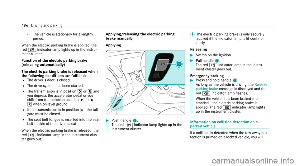
Applying #
Push handle 1.
The red! indicator lamp lights up in the
instrument clus ter. %
The electric parking brake is only securely
applied if the indicator lamp is lit continu‐
ously.
Re leasing #
Swit chon the ignition. #
Pull handle 1.
The red! indicator lamp in the instru‐
ment clus ter goes out.
Emer gency braking #
Press and hold handle 1.
As long as theve hicle is driving, theRelease
parking brake message is displa yed and the
re d! indicator lamp flashes.
When theve hicle has been braked to a
st andstill, the electric parking brake is
applied. The red! indicator lamp lights
up in the instrument clus ter. Information on collision de
tection on a
pa rked vehicle If a collision is de
tected when theto w- aw ay pro‐
te ction is primed on a loc kedve hicle, you will 18 6
Driving and pa rking
Page 190 of 453
re
cei vea notification in the multimedia sy stem
when you swit chon the ignition.
Yo u will recei veinformation about thefo llowing
points:
R The area of theve hicle that may ha vebeen
damaged.
R The forc e of the impact.
The following situations can lead toinadver tent
acti vation:
R The pa rked vehicle is mo ved, e.g. in a two-
st or ey garage.
% Deactivate tow- aw ay protection in order to
pr eve nt inadver tent acti vation. If you deacti‐
va te tow- aw ay protection, collision de tection
will also be deactivated.
Sy stem limits
De tection may be restricted in thefo llowing sit‐
uations:
R theve hicle is damaged without impact, e.g. if
an outside mir ror is torn off or the paint is
damaged byakey
R an impact occurs at low speed R
the electric parking brake is not applied Driving and driving saf
ety sy stems Driving sy
stems and your responsibility Yo
ur vehicle is equipped with driving sy stems
which assist you in driving, parking and manoeu‐
vring theve hicle. The driving sy stems are only
aids. They are not a substitute foryo ur attention
to the sur roundings and do not relie ve you of
yo ur responsibility per taining toroad traf fic la w.
The driver is alw aysre sponsible for maintaining
a safe dis tance totheve hicle in front, forve hicle
speed, for braking in good time and forst ay ing
in lane. Pay attention tothe traf fic conditions at
all times and inter vene when necessa ry. Be
aw are of the limitations rega rding the safe use of
th ese sy stems.
Driving sy stems can neither reduce therisk of
accident if youfa ilto adapt your driving style nor
ov erride the la wsof ph ysics. They cannot alw ays
ta ke into account road, weather or traf fic condi‐
tions. In
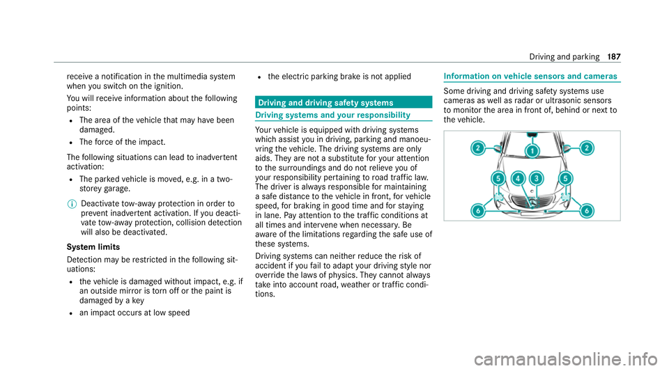
fo rm ation on vehicle sensors and cameras Some driving and driving saf
ety sy stems use
cameras as well as radar or ultrasonic sensors
to monitor the area in front of, behind or next to
th eve hicle. Driving and parking
187