MERCEDES-BENZ G-CLASS SUV 2014 Owners Manual
Manufacturer: MERCEDES-BENZ, Model Year: 2014, Model line: G-CLASS SUV, Model: MERCEDES-BENZ G-CLASS SUV 2014Pages: 272, PDF Size: 39.13 MB
Page 131 of 272
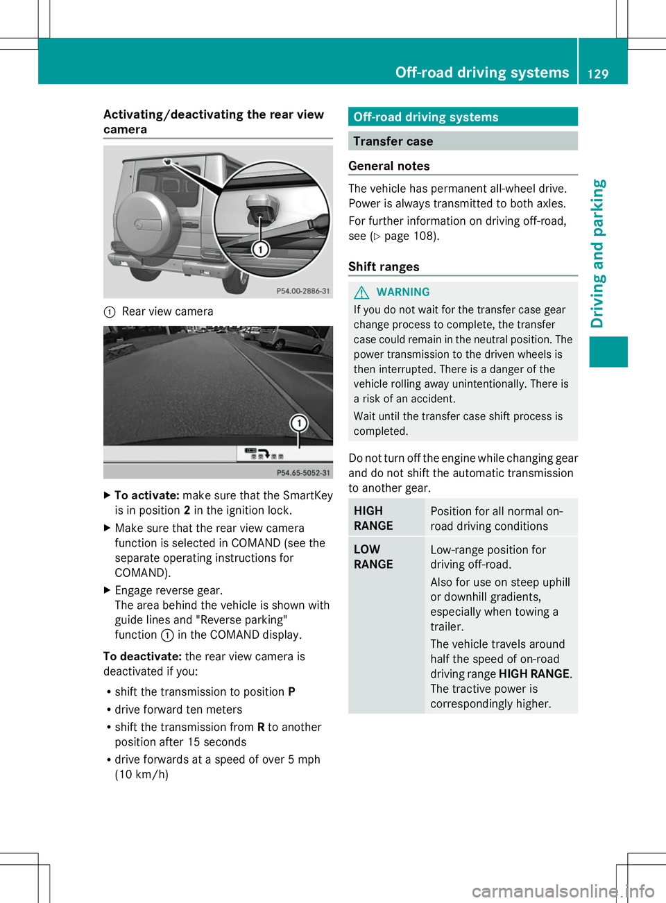
Activating/deactivating the rear view
camera :
Rear view camera X
To activate: make sure that the SmartKey
is in position 2in the ignition lock.
X Make sure that the rear view camera
function is selected in COMAND (see the
separate operating instructions for
COMAND).
X Engage reverse gear.
The area behind the vehicle is shown with
guide lines and "Reverse parking"
function :in the COMAND display.
To deactivate: the rear view camera is
deactivated if you:
R shift the transmission to position P
R drive forward ten meters
R shift the transmission from Rto another
position after 15 seconds
R drive forwards at a speed of over 5 mph
(10 km/h) Off-road driving systems
Transfer case
General notes The vehicle has permanent all-wheel drive.
Power is always transmitted to both axles.
For further information on driving off-road,
see (Y
page 108).
Shift ranges G
WARNING
If you do not wait for the transfer case gear
change process to complete, the transfer
case could remain in the neutral position. The
power transmission to the driven wheels is
then interrupted. There is a danger of the
vehicle rolling away unintentionally. There is
a risk of an accident.
Wait until the transfer case shift process is
completed.
Do not turn off the engine while changing gear
and do not shift the automatic transmission
to another gear. HIGH
RANGE
Position for all normal on-
road driving conditions
LOW
RANGE
Low-range position for
driving off-road.
Also for use on steep uphill
or downhill gradients,
especially when towing a
trailer.
The vehicle travels around
half the speed of on-road
driving range
HIGH RANGE.
The tractive power is
correspondingly higher. Off-road driving systems
129Driving and parking Z
Page 132 of 272
Shifting the transfer case
Important safety notes
G
WARNING
When the transfer case is in the neutral
position, power transmission to the driven
wheels is interrupted. As a result, the vehicle
could roll away. There is a risk of an accident.
Secure the vehicle with the parking brake, and
on uphill or downhill gradients, also secure it
with a device such as a wheel chock.
Always wait for the gear change process from
HIGH RANGE toLOW RANGE and from
LOW RANGE toHIGH RANGE to complete.
Do not turn off the engine while changing gear
and do not shift the automatic transmission
to another gear.
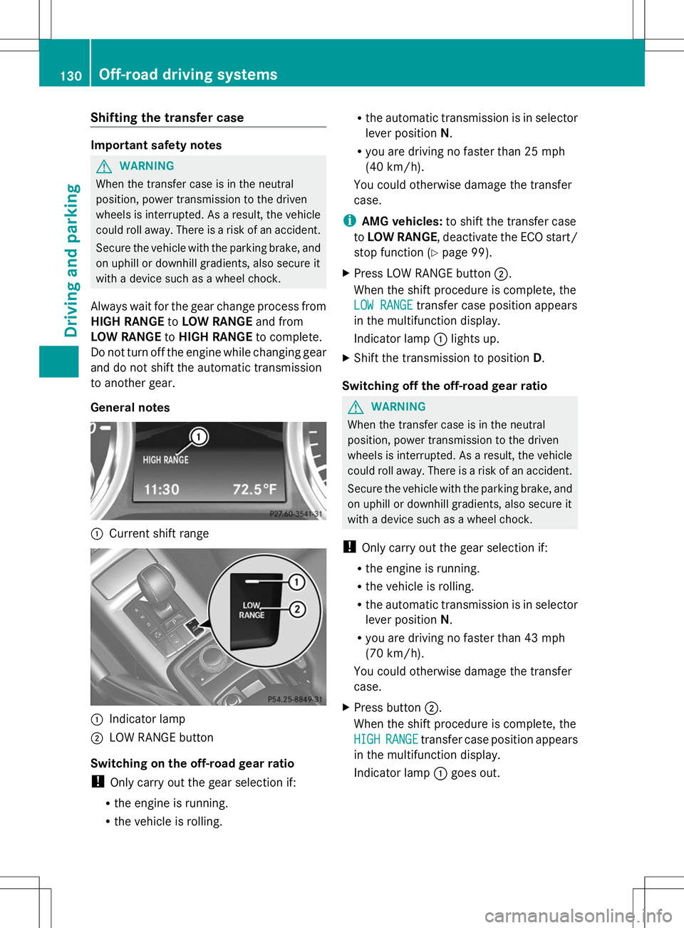
General notes :
Current shift range :
Indicator lamp
; LOW RANGE button
Switching on the off-road gear ratio
! Only carry out the gear selection if:
R the engine is running.
R the vehicle is rolling. R
the automatic transmission is in selector
lever position N.
R you are driving no faster than 25 mph
(40 km/h).
You could otherwise damage the transfer
case.
i AMG vehicles: to shift the transfer case
to LOW RANGE, deactivate the ECO start/
stop function (Y page 99).
X Press LOW RANGE button ;.
When the shift procedure is complete, the
LOW RANGE LOW RANGE transfer case position appears
in the multifunction display.
Indicator lamp :lights up.
X Shift the transmission to position D.
Switching off the off-road gear ratio G
WARNING
When the transfer case is in the neutral
position, power transmission to the driven
wheels is interrupted. As a result, the vehicle
could roll away. There is a risk of an accident.
Secure the vehicle with the parking brake, and
on uphill or downhill gradients, also secure it
with a device such as a wheel chock.
! Only carry out the gear selection if:
R the engine is running.
R the vehicle is rolling.
R the automatic transmission is in selector
lever position N.
R you are driving no faster than 43 mph
(70 km/h).
You could otherwise damage the transfer
case.
X Press button ;.
When the shift procedure is complete, the
HIGH
HIGH RANGE RANGE transfer case position appears
in the multifunction display.
Indicator lamp :goes out. 130
Off-road driving systemsDriving and parking
Page 133 of 272
If the gear change is not completed, the
following messages could appear in the
display:
R TC shift Conditions Not Fulfilled TC shift Conditions Not Fulfilled
You have not met one or more shift
conditions.
R TC NEUTRAL On
TC NEUTRAL On
The transfer case has canceled the gear
change process and is in N. Transfer case
position N
N appears in the multifunction
display.
R TC shift Canceled TC shift Canceled
The transfer case has not performed the
gear change process.
X Carry out the gear change process again.
Make sure to meet all conditions for
changing gears.
R TC Malfunction Visit Workshop
TC Malfunction Visit Workshop
There is a malfunction in the transfer case.
X Do not shift the transfer case.
X Have the vehicle checked as soon as
possible at a qualified specialist workshop.
Shifting to neutral G
WARNING
When the transfer case is in the neutral
position, power transmission to the driven
wheels is interrupted. As a result, the vehicle
could roll away. There is a risk of an accident.
Secure the vehicle with the parking brake, and
on uphill or downhill gradients, also secure it
with a device such as a wheel chock.
X Turn the SmartKey to position 2in the
ignition lock (Y page 97).
X Apply the parking brake.
X Depress the brake pedal.
X Move the selector lever to position
N(Y page 100).
X Press and hold LOW RANGE button ;for
approximately 10 seconds.
When the shift procedure is complete, the
TC In Neutral TC In Neutral message appears in the
multifunction display for 5 seconds. If the gear change is not completed, the
following messages could appear in the
display (Y
page 144).
i If the transfer case is in Neutral, the
SmartKey is in the ignition lock and you
open the driver's door, the TC In TC In
Neutral Neutral message appears in the
multifunction display. If you then release
the parking brake, a warning tone will
sound. Differential locks
General notes G
WARNING
When the differential locks are engaged, ABS,
4ETS, ESP ®
and BAS are deactivated. As a
result, the wheels could lock when braking
and the braking distance is increased. There
is a risk of an accident.
Disengage the differential locks immediately
on firm surfaces with good grip.
! In order to avoid damage to the transfer
case, you must operate the vehicle on a
dynamometer (1-axle dynamometer) only
if:
R the axle not driven on is jacked up
or
R the corresponding propeller shaft is
disconnected and the transfer case
differential lock is engaged.
Otherwise, the transfer case can be
damaged.
Differential locks improve the traction of the
vehicle. Off-road driving systems
131Driving and parking Z
Page 134 of 272
Your vehicle is equipped with a differential
lock each for:
R the transfer case: this controls the balance
between the front and rear axles.
R the rear axle: this controls the balance
between the wheels on the rear axle.
R the front axle: this controls the balance
between the wheels on the front axle.
Information on differential and
differential locks When the vehicle drives around a curve, the
wheels on the outside of the curve must cover
a greater distance. Therefore, the wheels turn
more rapidly than on the inside. The
differential, a transmission in the drive train,
compensates for these different rotational
speeds, making cornering possible.
The disadvantage of a differential is that more
power is transferred to the wheels that have
the least grip. An example: a wheel of a driven
axle is on a snow-covered surface and
therefore does not have any traction. The
differential causes this wheel to be subjected
to the strongest driving force, as the flow of
force takes the path of least resistance. The
opposite wheel on this axle, however, which
stands on firm ground and could therefore
allow propulsion, receives no driving power.
4ETS compensates for this disadvantage.
4ETS provides good steerability by
automatically braking the spinning wheel.
4ETS provides the wheel on the firm surface
with more drive force, which in turn provides
propulsion.
ESP® and 4ETS are traction systems that are
ideal for road driving and suitable for light off-
road driving. The LOW RANGEoff-road gear
also improves off-road capability.
Moreover, the more difficult conditions in off-
road driving require further measures such as
locking one or several differentials. Your
vehicle is equipped with three differential
locks: R
a central differential lock for the transfer
case,
R a differential lock for the front axle and
R a differential lock for the rear axle.
Each differential lock can be engaged with the
respective switch on the center console. If
the transfer case differential is disabled, the
front and rear wheels turn at the same speed.
If the differential for the rear axle is locked,
both rear wheels turn at the same speed,
regardless of their individual torques. Please
note that activating the differential locks
severely restricts the vehicle's steerability.
Please note that the functions of the
differential are absolutely necessary for
driving on paved roads. The differential locks
must never be engaged when driving on
paved roads. Otherwise, the vehicle may not
be steerable and you could lose control of the
vehicle. The differential locks must therefore
only be engaged when driving off-road. You
may only engage the differential locks if the
functions of the 4ETS and ESP ®
driving
systems and the LOW RANGEoff-road gear
are insufficient.
i The differential locks are only available in
the LOW RANGE off-road gear.
Engaging the differential locks Important safety notes
G
WARNING
When differential locks are engaged on a firm,
high-grip surface, the vehicle's steerability is
greatly impaired. In particular, engaging the
differential locks when cornering could lead
to you losing control of the vehicle. There is a
risk of an accident.
Disengage the differential locks immediately
on firm surfaces with good grip. G
WARNING
When the differential locks are engaged, ABS,
4ETS, ESP ®
and BAS are deactivated. As a
result, the wheels could lock when braking 132
Off-road driving systemsDriving and parking
Page 135 of 272
and the braking distance is increased. There
is a risk of an accident.
Disengage the differential locks immediately
on firm surfaces with good grip.
! Only engage the differential locks when:
R you are driving at walking pace.
R the driven wheels are not spinning.
R you are not driving on a firm road surface.
General notes
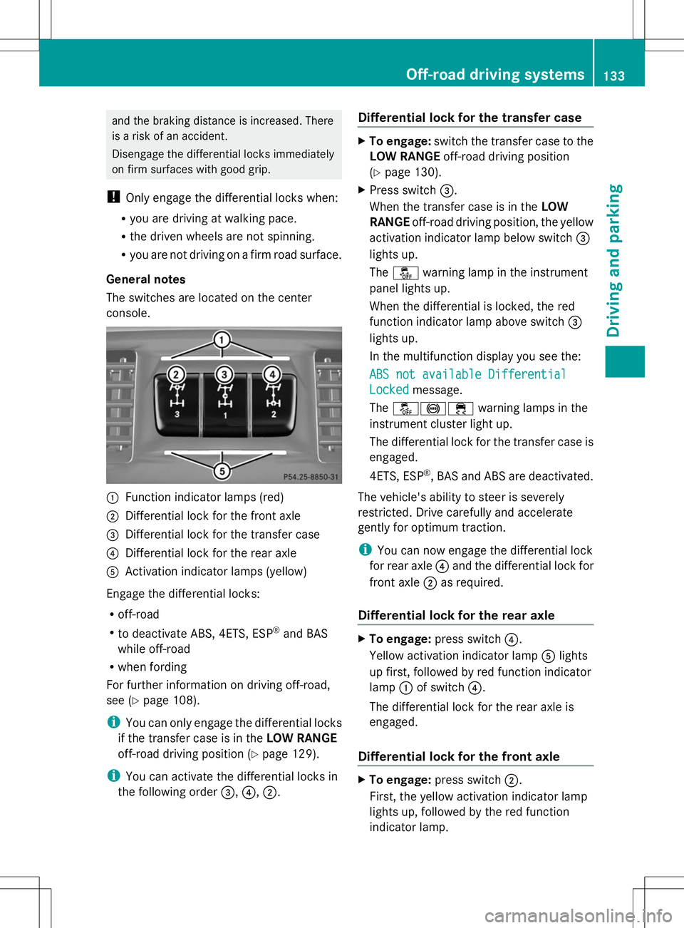
The switches are located on the center
console. :
Function indicator lamps (red)
; Differential lock for the front axle
= Differential lock for the transfer case
? Differential lock for the rear axle
A Activation indicator lamps (yellow)
Engage the differential locks:
R off-road
R to deactivate ABS, 4ETS, ESP ®
and BAS
while off-road
R when fording
For further information on driving off-road,
see (Y page 108).
i You can only engage the differential locks
if the transfer case is in the LOW RANGE
off-road driving position (Y page 129).
i You can activate the differential locks in
the following order =,?,;. Differential lock for the transfer case X
To engage: switch the transfer case to the
LOW RANGE off-road driving position
(Y page 130).
X Press switch =.
When the transfer case is in the LOW
RANGE off-road driving position, the yellow
activation indicator lamp below switch =
lights up.
The å warning lamp in the instrument
panel lights up.
When the differential is locked, the red
function indicator lamp above switch =
lights up.
In the multifunction display you see the:
ABS not available Differential
ABS not available Differential
Locked Locked message.
The å!÷ warning lamps in the
instrument cluster light up.
The differential lock for the transfer case is
engaged.
4ETS, ESP ®
, BAS and ABS are deactivated.
The vehicle's ability to steer is severely
restricted. Drive carefully and accelerate
gently for optimum traction.
i You can now engage the differential lock
for rear axle ?and the differential lock for
front axle ;as required.
Differential lock for the rear axle X
To engage: press switch ?.
Yellow activation indicator lamp Alights
up first, followed by red function indicator
lamp :of switch ?.
The differential lock for the rear axle is
engaged.
Differential lock for the front axle X
To engage: press switch ;.
First, the yellow activation indicator lamp
lights up, followed by the red function
indicator lamp. Off-road driving systems
133Driving and parking Z
Page 136 of 272
The differential lock for the front axle is
engaged.
Disengaging the differential locks You can disengage the differential locks in the
following order: ;,?,=.
X To simultaneously disengage all
differential locks: press switch=.
Yellow activation indicator lamps Aand
red function indicator lamps :go out.
After approximately three seconds of
normal driving, ABS, 4ETS, ESP ®
and BAS
are activated.
The ABS ABS not
notavailable
available Differential
Differential
Locked
Locked message disappears in the
multifunction display and the å,!
and ÷ warning lamps in the instrument
cluster go out.
X Shift the transfer case to the HIGH
RANGE on-road position (Y page 130).
i If red function indicator lamps :do not
go out after disengaging the differential
locks, bring the vehicle to a standstill in
accordance with the traffic conditions.
Then continue driving, as the load change
can release the differential locks. Towing a trailer
Notes on towing a trailer
Important safety notes G
WARNING
If you rest your foot on the brake pedal while
driving, the braking system can overheat. This
increases the stopping distance and can even
cause the braking system to fail. There is a
risk of an accident.
Never use the brake pedal as a footrest. Never
depress the brake pedal and the accelerator
pedal at the same time. G
WARNING
When the vehicle/trailer combination begins
to lurch, you could lose control of it. The
vehicle/trailer combination could even
rollover. There is a risk of an accident.
On no account should you attempt to
straighten up the vehicle/trailer combination
by increasing the speed. Reduce vehicle
speed and do not countersteer. Apply the
brake as necessary. G
WARNING
If you install a ball coupling other than the one
delivered with the vehicle, the trailer tow hitch
and the rear axle may be overloaded. This
applies especially if the ball coupling in
question is longer or angled differently. This
could seriously impair the driving
characteristics and the trailer can come
loose. There is a risk of an accident.
Only install the ball coupling delivered with
the vehicle or a ball coupling that is designed
to meet your trailer towing requirements. Do
not modify the ball coupling or the trailer tow
hitch. G
WARNING
If the ball coupling is not installed correctly or
not secured with the bolt provided and the
corresponding spring cotter, the trailer may
come loose. There is a risk of an accident.
Always install and secure the ball coupling as
described. Before every journey, ensure that
the ball coupling is secured with the bolt and
the corresponding spring cotter.
Please observe the manufacturer's operating
instructions for the trailer coupling if a
detachable trailer coupling is used.
You will find the applicable permissible
values, which must not be exceeded, in the
vehicle documents. You will find the values
approved by the manufacturer on the vehicle
identification plates and those for the towing
vehicle in the "Technical data" section
(Y page 258). 134
Towing a trailerDriving and parking
Page 137 of 272
Couple and uncouple the trailer carefully. If
you do not couple the trailer to the towing
vehicle correctly, the trailer could become
detached.
Make sure that the following values are not
exceeded:
R the permissible trailer drawbar noseweight
R the permissible trailer load
R the permissible rear axle load of the towing
vehicle
R the maximum permissible gross vehicle
weight of both the towing vehicle and the
trailer
When towing a trailer, your vehicle's handling
characteristics will be different in comparison
with when driving without a trailer.
The vehicle/trailer combination:
R is heavier
R is restricted in its acceleration and
gradient-climbing capability
R has an increased braking distance
R is affected more by strong crosswinds
R demands more sensitive steering
R has a larger turning circle
This could impair the handling
characteristics.
When towing a trailer, always adjust your
speed to the current road and weather
conditions. Do not exceed the maximum
permissible speed for your vehicle/trailer
combination.
Driving tips X
On long and steep downhill gradients,
select shift range 1,2or 3(Y page 101) in
good time.
i This also applies if you have activated
cruise control or SPEEDTRONIC.
X If necessary, shift the transfer case to LOW
RANGE(Y page 130).
This will use the braking effect of the
engine, so that less braking will be required
to maintain the speed. This relieves the load on the brake system and prevents the
brakes from overheating and wearing too
quickly. If you need additional braking,
depress the brake pedal repeatedly rather
than continuously.
The maximum permissible speed for vehicle/
trailer combinations depends on the type of
trailer. Before beginning the journey, check
the trailer's documents to see what the
maximum permissible speed is. Observe the
legally prescribed maximum speed in the
relevant country.
For certain Mercedes-Benz vehicles, the
maximum permissible rear axle load is
increased when towing a trailer. Refer to the
"Technical data" section to find out whether
this applies to your vehicle. If you utilize any
of the added maximum rear axle load when
towing a trailer, the vehicle/trailer
combination may not exceed a maximum
speed of 60 mph (100 km/h) for reasons
concerning the operating permit. This also
applies in countries in which the permissible
maximum speed for vehicle/trailer
combinations is above 60 mph (100 km/h).
When towing a trailer, your vehicle's handling
characteristics will be different in comparison
to when driving without a trailer and it will
consume more fuel.
On long and steep downhill gradients, you
must select shift range 1,2or 3in good time.
i This also applies if you have activated
cruise control or DISTRONIC PLUS.
This will use the braking effect of the engine,
so that less braking will be required to
maintain the speed. This relieves the load on
the brake system and prevents the brakes
from overheating and wearing too quickly. If
you need additional braking, depress the
brake pedal repeatedly rather than
continuously. Towing a trailer
135Driving and parking Z
Page 138 of 272
Driving tips
If the trailer swings from side to side:
X Do not accelerate.
X Do not counter-steer.
X Brake if necessary.
R Maintain a greater distance from the
vehicle in front than when driving without a
trailer.
R Avoid braking abruptly. If possible, brake
gently at first to allow the trailer to run on.
Then, increase the braking force rapidly.
R The values given for gradient-climbing
capabilities from a standstill refer to sea
level. When driving in mountainous areas,
note that the power output of the engine,
and consequently the vehicle's gradient-
climbing capability, decrease with
increasing altitude. Assembling the ball coupling
Assembling the ball coupling G
WARNING
The ball coupling can be damaged if the nut
on the ball coupling is tightened using the
incorrect torque. As a result, the trailer may
detach. There is a risk of an accident.
Immediately after installing, have the
tightening torque checked at a qualified
specialist workshop.
! Mercedes-Benz recommends that you
only use ball couplings tested and
approved for use on Mercedes-Benz
vehicles. This helps to avoid damage to the
vehicle.
Observe the manufacturer's installation
instructions if you use a ball coupling other
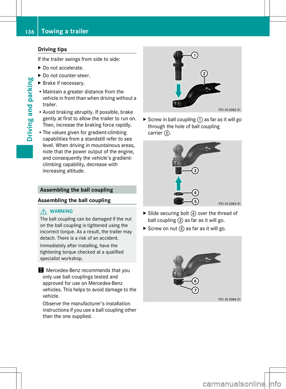
than the one supplied. X
Screw in ball coupling :as far as it will go
through the hole of ball coupling
carrier ;. X
Slide securing bolt ?over the thread of
ball coupling =as far as it will go.
X Screw on nut Aas far as it will go. 136
Towing a trailerDriving and pa
rking
Page 139 of 272
X
Using a torque wrench, tighten nut Bwith
a torque of 516 lb-ft (700 Nm).
X Check that thread Cprotruding below nut
B has the minimum required length of
0.32 in (8 mm).
X Check the assembled ball coupling for
correct installation.
i Also observe the height of the trailer
coupling and the trailer manufacturer's
instructions.
i Depending on the height of the trailer
coupling, you may have to turn the ball
coupling 180° to install it on the ball
coupling carrier. The assembly is otherwise
identical. Installing the ball coupling
G
WARNING
If the ball coupling is not installed correctly or
not secured with the bolt provided and the
corresponding spring cotter, the trailer may
come loose. There is a risk of an accident.
Always install and secure the ball coupling as
described. Before every journey, ensure that
the ball coupling is secured with the bolt and
the corresponding spring cotter. G
WARNING
If the ball coupling is not installed and secured
correctly it can become detached while the
vehicle is in motion and fall onto the road.
There is a risk of accident and injury.
Always install and secure the ball coupling as
described. Before every journey, ensure that
the ball coupling is secured with the bolt and
the corresponding spring cotter. X
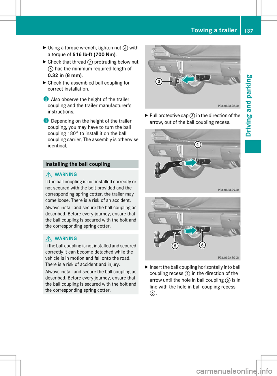
Pull protective cap =in the direction of the
arrow, out of the ball coupling recess. X
Insert the ball coupling horizontally into ball
coupling recess ?in the direction of the
arrow until the hole in ball coupling Ais in
line with the hole in ball coupling recess
B. Towing a trailer
137Driving and parking Z
Page 140 of 272
X
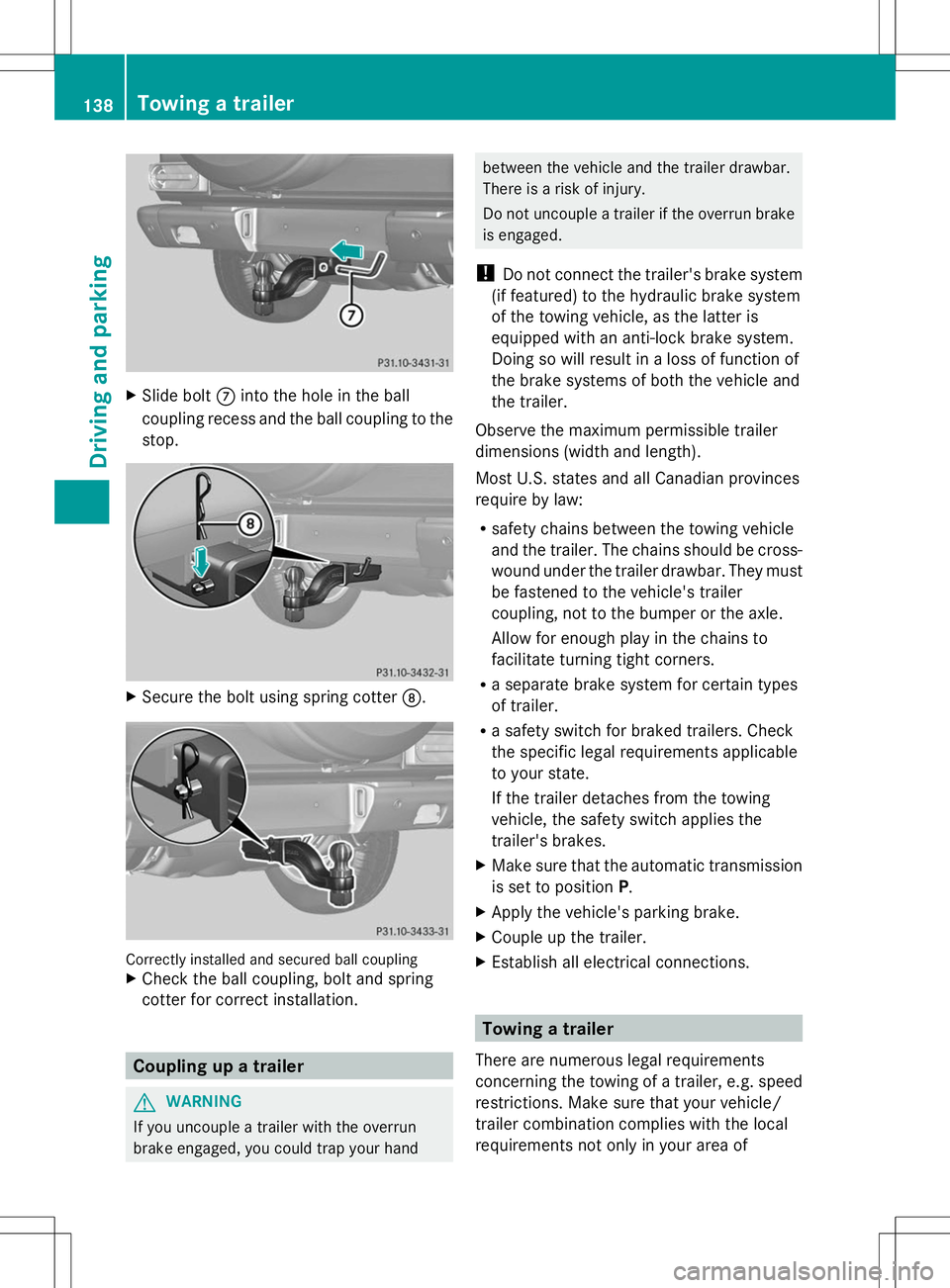
Slide bolt Cinto the hole in the ball
coupling recess and the ball coupling to the
stop. X
Secure the bolt using spring cotter D.Correctly installed and secured ball coupling
X Check the ball coupling, bolt and spring
cotter for correct installation. Coupling up a trailer
G
WARNING
If you uncouple a trailer with the overrun
brake engaged, you could trap your hand between the vehicle and the trailer drawbar.
There is a risk of injury.
Do not uncouple a trailer if the overrun brake
is engaged.
! Do not connect the trailer's brake system
(if featured) to the hydraulic brake system
of the towing vehicle, as the latter is
equipped with an anti-lock brake system.
Doing so will result in a loss of function of
the brake systems of both the vehicle and
the trailer.
Observe the maximum permissible trailer
dimensions (width and length).
Most U.S. states and all Canadian provinces
require by law:
R safety chains between the towing vehicle
and the trailer. The chains should be cross-
wound under the trailer drawbar. They must
be fastened to the vehicle's trailer
coupling, not to the bumper or the axle.
Allow for enough play in the chains to
facilitate turning tight corners.
R a separate brake system for certain types
of trailer.
R a safety switch for braked trailers. Check
the specific legal requirements applicable
to your state.
If the trailer detaches from the towing
vehicle, the safety switch applies the
trailer's brakes.
X Make sure that the automatic transmission
is set to position P.
X Apply the vehicle's parking brake.
X Couple up the trailer.
X Establish all electrical connections. Towing a trailer
There are numerous legal requirements
concerning the towing of a trailer, e.g. speed
restrictions. Make sure that your vehicle/
trailer combination complies with the local
requirements not only in your area of 138
Towing a trailerDriving and parking