change wheel MERCEDES-BENZ G-CLASS SUV 2016 User Guide
[x] Cancel search | Manufacturer: MERCEDES-BENZ, Model Year: 2016, Model line: G-CLASS SUV, Model: MERCEDES-BENZ G-CLASS SUV 2016Pages: 261, PDF Size: 6.01 MB
Page 123 of 261
Observe the following notes:
R stop the vehicle before you drive off-road and,
if necessary, shift the transfer case to the
LOW RANGE off-road driving position
(Y page 124)
R engage the differential locks if necessary
(Y page 126)
i ABS,4
ETS, ESP ®
and BAS are deactivated
while the differential locks are engaged. This
allowst he front wheels to lock briefly, so that
they can dig into aloose surface. However,
please note that locked wheels skid and can
no longer steer.
R Make sure that items of luggage and loads are
stowed safely and are well secured
(Y page 203).
R To avoid damaging the vehicle, make sure
there is always sufficient ground clearance.
R Alwaysk eep the engine running and in gear
when driving on adownhill gradient.
R Alwaysk eep the engine running and in gear
when driving on aslope.
R Drive slowly and evenly, if necessary at walk-
ing pace.
R Ensure that the wheels are in contact with the
ground at all times.
R Drive with extreme care on unknown off-road
routes where visibility is poor. For safety rea- sons, get out of the vehicle first and survey
the off-road route.
R Check the depth of water before fording rivers
and streams.
R Watch out for obstacles.
R Alwaysk eep the doors, the rear door, the side
windows and the sliding sunroof closed while
the vehicle is in motion.
R Do not deviate from marked routes.
R Match your speed to the terrain. The rougher,
steeper or more ruts on the terrain, the slower your speed should be.
R Do not jump with the vehicle. This will inter-
rupt the vehicle's propulsion.
R Avoid high engine speeds. Drive at appropri-
ate engine speeds.
R Alwaysc heck the vehicle for damage after off-
road driving.
Do not use the HOLD function when driving off- road, on steep uphillord ownhill gradients or on
slippery or loose surfaces. The HOLD function
cannot hold the vehicle on such surfaces. You can obtain further information aboutr
etro-
fittin gspecial all-terrain tyres from aqualified
specialis tworkshop.
Checklist before off-roa ddriving X
Engine oil level: check the engine oil and top
it up if necessary.
When driving on steep gradients, the oil level must be sufficiently high to ensure acorrect
oil supply in th evehicle.
X Hav ethe AdBlue ®
level checked at aqualified
specialist workshop (Y page 111).
X Tyre-change tool kit: check that thejackis
working and mak esure that th ewheel
wrench, arobus ttow cable and afolding
spade are in th evehicle.
X Wheels and tyres: check thetyret read
dept hand tyr epressure.
X Chec kfor damage and remove any foreign
objects, e.g .small stones, fro mthewheels/
tyres.
X Replace any missing valv ecaps.
X Replace dented or damage dwheels .Also
check th espare wheel.
X Wheels: dented or ben twheels can lead to a
loss of tyr epressure and damage to th etyre
bead. Before driving off-road, check the
wheels and replac ethemifn ecessary.
Checklist after off-roa ddriving !
If you detect damage to the vehicl
eafter
driving off-road, have the vehicle checked
immediately at aqualified specialist work-
shop.
Driving over rough terrain places greater
demands on your vehicle than driving on normal
roads. After driving off-road, check the vehicle.
This allowsy ou to detect damage promptly and
reduce the risk of an accident to yourselfa nd
other road users.
X Shift the transfer case to the on-road position
HIGH RANGE (Ypage 124).
X Disengage the differential locks
(Y page 127).
X Cleant he headlamps and rear lights and
check for damage.
X Cleant he front and rear licence plates.
X Cleant he wheels and tyres with awater jet
and remove any foreign objects. 120
Drivingt
ipsDriving and parking
Page 127 of 261
Off-road driving systems
Transfer case
General notes The vehicle has permanent all-wheel drive. The
front and rear axles are constantly driven.
Further information on driving off-road
(Y page 119).
Shift ranges HIGH
RANGE
Position for all normal on-
road driving conditions.
LOW RANGE
Low-range position for driving
off-road.
Also for use on steep uphill or downhill gradients, especially
when towin gatrailer.
The vehicle travels around
half the speed of on-road driv-
ing range HIGH RANGE.T he
tractive powerisc orrespond-
ingly higher. Shiftin
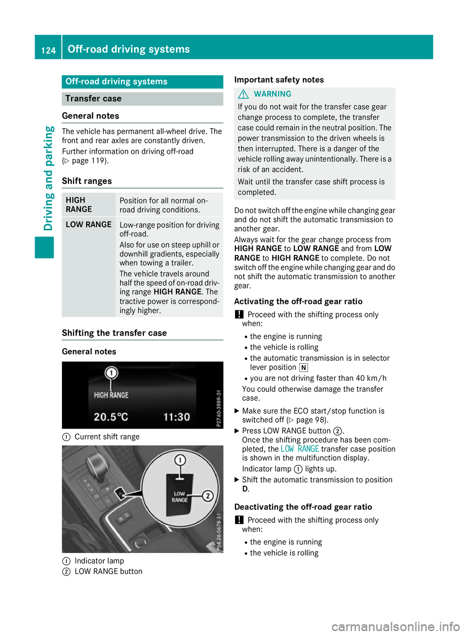
gthe transfer case General notes
:
Curren tshif trange :
Indicator lamp
; LOW RANGE button Important safety notes G
WARNING
If yo udon ot waitf or the transfer case gear
change process to complete, the transfer
case coul dremai ninthe neutral position. The
power transmission to the drive nwheels is
then interrupted. There is adange rofthe
vehicl erolling awayu nintentionally.T here is a
risk of an accident.
Waitu ntil the transfer case shift process is
completed.
Do not switch off the engine while changing gear and do not shift the automatic transmission to
another gear.
Always waitf or the gearchange process from
HIGH RANGE toLOW RANGE and fromLOW
RANGE toHIGH RANGE to complete. Do not
switch off the engine while changing geara nd do
not shift the automatic transmission to another gear.
Activating the off-road gear ratio ! Proceed with the shifting process only
when:
R the engine is running
R the vehicl eisrolling
R the automatic transmission is in selector
leve rposition i
R you are not driving faster than 40 km/h
You coul dotherwise damage the transfer
case.
X Make sure the ECO start/stop function is
switched off (Y page98).
X Press LOW RANGE button ;.
Once the shifting procedure has been com-
pleted, the LOW RANGE LOW RANGE transfer case position
is show ninthe multifunction display.
Indicator lamp :lights up.
X Shift the automatic transmission to position
D.
Deactivatin gthe off-road gear ratio
! Proceed with the shifting process only
when:
R the engine is running
R the vehicl eisrolling 124
Off-roa
ddriving systemsDriving and parking
Page 128 of 261
R
the automatic transmission is in selector
lever position i
R youa renot drivin gfastert ha n7 0km/h
Yo uc ould otherwis edamag ethe transfer
case.
X Press button ;.
Once the shiftin gprocedur ehasbeen com-
pleted, the HIGH
HIGH RANGE RANGE transfe rcasep osit ion
is shown in the multifunctio ndisplay.
Indicato rlamp :goes out.
If the shiftin gprocedur eisunsuccessful, the
multifunctio ndisplay mayshowt he following
messages:
R TC shift condition snot fulfilled
TC shift condition snot fulfilled
One or mor eshift conditions ha snot been
met.
R TC neutra lon
TC neutra lon
The transfe rcaseh ascancelle dthe shifting
procedur eand is in position N.
R TC shift cancelled
TC shift cancelled
The transfe rcaseh ascancelle dthe gear
change process.
X Repeat the gear change process.
Make sure al lconditions for gear changing are
met.
R TC malfunction Visit workshop
TC malfunction Visit workshop
The transfe rcaseisf aulty.
X Do not shift the transfe rcase.
X Hav ethe vehicl echecked as soo naspossible
at aq uali fied specialis tworkshop.
Shifting to neutral G
WARNING
If you do not wai tfor the transfer case gear
change process to complete, the transfer
case coul dremai ninthe neutral position. The
power transmission to the drive nwheels is
then interrupted. There is adange rofthe
vehicl erolling awayu nintentionally.T here is a
risk of an accident.
Waitu ntil the transfer case shift process is
completed.
X Turn the key to position 2in the ignitio nlock.
X Apply the parking brake.
X Depress the brake pedal. X
Shift the automatic transmissio ntoposition
N.
X Press and hol dLOW RANG Ebutton ;for
approximately ten seconds.
Whe nthe shift procedure is complete, the
multifunction display shows the TC TCNeutral
Neutral
on
on message for five seconds.
If the shifting procedur eisunsuccessful, the
multifunction displaym ay show the following
messages (Y page 149).
If the transfer case is in Neutral,the key is in the
ignition lock and you open the driver's door, the
TC Neutral on
TC Neutral on message appears in the multi-
function display. If you then release the parking
brake, awarning tone will sound. Differentia
llocks
General notes G
WARNING
When th edifferential locks are engaged, ABS,
4ETS, ESP ®
and BAS are deactivated. This
coul dcauset he wheels to lock and increases
the braking distance. There is arisk of an
accident.
Disengage the differential locks immediately
on firm surfaces with good grip.
! To prevent damage to the transfer case, you
may only operate the vehicl eonaroller dyna-
mometer (single-axle roller dynamometer) if:
R the axle that is not being drive nisraised.
or
R the corresponding propellers haft is dis-
connected and the transfer case differen-
tial lock is engaged.
Otherwise, the transfer case can be damaged.
Differentia llocks improv ethe traction of the
vehicle.
Yourv ehicleise quipped with adifferential lock
each for:
R the transfer case: this controls the balance
between the front and rear axles
R the rear axle :this controls the balance
between the wheels on the rear axle
R the front axle :this controls the balance
between the wheels on the front axle Off-roa
ddriving systems
125Driving and parking Z
Page 141 of 261
i
Vehicles for the United Kingdom: this func-
tion is unavailable.
Selects language
X Press the =or; button on the steering
wheel to select the Settings
Settingsmenu.
X Press the :or9 button to select the
Instrument cluster
Instrument cluster submenu.
X Press ato confirm.
X Press :or9 to select the Language:
Language:
function.
You will see the current setting.
X Press ato confirm.
X Press the :or9 button to change the
setting.
X Press ato store the entry.
Time/date Setting the date
X Press the =or; button on the steering
wheel to select the Settings Settingsmenu.
X Press :or9 to select the Time/Date Time/Date
submenu.
X Press ato confirm.
X Press :or9 to select the Date: Date:func-
tion.
You will see the current setting.
X To set the date: pressaagain.
X Press =or; to switch between the
day, month and year.
X Press :or9 to set the day, month or
year.
X Press ato store the entry.
The display shows the selected date.
Setting the time X Press the =or; button on the steering
wheel to select the Settings
Settings menu.
X Press :or9 to select the Time/Date Time/Date
submenu.
X Press ato confirm.
X Press :or9 to select the Time:
Time:func-
tion.
You will see the current setting.
X To set the time: pressaagain.
X Press =or; to switch between hours
and minutes. X
Press :or9 to set the hours or
minutes.
X Press ato store the entry.
The display shows the selected time.
Lights Setting the daytime driving lights
The Daytime driving lights Daytime driving lights function can
only be switched on with the engine switched
off.
X Press the =or; button on the steering
wheel to select the Settings Settingsmenu.
X Press the :or9 button to select the
Lights
Lights submenu.
X Press ato confirm.
X Press the :or9 button to select the
Daytime driving lights
Daytime driving lights function.
If the Daytime
Daytime driving
drivinglights
lightsfunction has
been switched on, the cone of light and the
W symbol are shown in red in the multi-
function display.
X Press ato save the setting.
Further information on daytime driving lights
(Y page 74).
Surround lighting and exterior lighting
delayed switch-off X Press the =or; button on the steering
wheel to select the Settings Settingsmenu.
X Press the :or9 button to select the
Lights
Lights submenu.
X Press ato confirm.
X Press the :or9 button to select the
Surround lighting
Surround lighting function.
When the Surround lighting
Surround lighting function has
been activated, the cone of light is shown in
red in the multifunction display.
X Press ato save the setting.
Activating exterior lighting delayed switch-off
temporarily:
X Before leaving the vehicle, turn the key to
position 0in the ignition lock (Y page 96).
X Turn the key to position 2in the ignition lock
(Y page 96).
Exterior lighting delayed switch-off is deacti-
vated.
Exterior lighting delayed switch-off is reactiva-
ted the next time you start the engine. 138
Menus and submenusOn-boardc
omputer and displays
Page 143 of 261
When the auxiliary heating is switched on,
make sure that:
R no flammable materials come into contact
with hot vehicle components
R the exhaust gas can escape from the
exhaust pipe unhindered
R the exhaust gas does not come into contact
with flammable materials.
! Operatin
gthe auxiliary heating/ventilation
draws on the vehicle battery. After you have
heated or ventilated the vehicle amaximum of
two times, drive for alonger distance.
Only vehicles with auxiliary heating have this
function (Y page 89).
In the Heating Heating submenu, you can select a
stored departure time or change adeparture
time.
The auxiliary heating timer function calculates
the switch-on time accordin gtothe outside
temperature so that the vehicle is preheated by the departure time. When the departure time isreached, the auxiliary heating continues to heat for afurther five minutes and then switches off.
The auxiliary heating selects the temperature
setting of the THERMATIC automatic climate
control.
You can switch the auxiliary heating on or off by
using the &auxiliary heating button on the
centre console or the remot econtrol.
Selecting the departure time or deactivat- ing aselected departure time
X Press the =or; button on the steering
wheel to select the Settings Settingsmenu.
X Press the :or9 button to select the
Heating
Heating submenu.
X Press ato confirm.
You will see the selected setting.
X Press ato confirm.
X Press the :or9 button to select one
of the three departur etimes or Timer
Timeroff
off(no
timer active).
X Press ato confirm.
If ad eparture time is selected, the yellow
indicator lamp lights up on the &auxiliary
heating button. Changing the departure time
X
Press the =or; buttonont hesteering
wheel to selec tthe Settings Settings menu.
X Pres sthe : or9 button to selec tthe
Heating
Heating submenu.
X Press ato confirm.
Yo uw ill see the selected setting.
X Press ato confirm.
X Press the :or9 button to select
Change A Change A, Change B
Change BorChange C
Change C.
X Press ato confirm.
You can now change the departure time.
X Press the =or; button to select the
displaytobec hanged: hours, minutes.
X Press the :or9 button to set the
selected display.
X Press ato store the entry.
The yellow indicator lamp on the &auxili-
ary heating button lights up.
Comfort Activating/deactivating the EASY-
ENTRY/EXIT feature
G
WARNING
When the EASY-ENTRY/EXI Tfeature adjusts
the steering wheel, you and other vehicle
occupants –particularl ychildren –could
become trapped. There is arisk of injury.
Whil ethe EASY-ENTRY/EXIT feature is mak-
ing adjustments, make sure that no one has
any body parts in the swee pofthe steering
wheel.
If someone is trapped:
R press one of the memory function position
buttons, or
R move the switch for steering whee ladjust-
ment in the opposite direction to that in
which the steering whee lismoving.
The adjustment process is stopped.
X Press the =or; button on the steering
whee ltoselect the Settings Settings menu.
X Press the :or9 button to select the
Convenience
Convenience submenu.
X Press ato confirm. 140
Menu
sand submenusOn-boar dcomputer and displays
Page 219 of 261
The ASSYST service interval display inform
syou
of the next service due date.
If as ervice due date has been exceeded, you
also hear awarning tone.
The multifunction display shows aservice mes-
sage for afew seconds, e.g.:
Service Ain999,999 km
Service Ain999,999 km
Service Ain..d ays
Service Ain..d ays
Service Adue
Service Adue
Service Aoverdue by 999,999 km
Service Aoverdue by 999,999 km
Service Aoverdue by .. days
Service Aoverdue by .. days
Maintaining the time-dependent service sched-
ule:
X Call up and noted own the service due date
before disconnectin gthe battery.
or X After reconnecting the battery, subtract the
battery disconnection periods from the ser-
vice date shown on the display.
The symbol and the letter indicate which type of service is due:
¯ Minor service A
A
± Major service B B
The ASSYST service interval display does not
take into account any periods of time during
which the battery is connected.
Hiding service messages X
To hide the service message, press the %
back button on the multifunction steering
wheel (Y page 132).
Displaying service messages Use the buttons on the multifunction steering
wheel.
X Switch the ignition on.
X Press =or; to select the standard
display menu on the steering wheel
(Y page 133).
X Press 9or: to select the ASSYST ser-
vice interval display.
The ¯ or± service symbol and the ser-
vice due date are displayed. Special service requirements The prescribed service interval is based on nor-
mal operation of the vehicle. Servic ework will
need to be performed more often if the vehicle is operated under arduous conditions or increased
loads, for example:
R regular city driving with frequent intermediate
stops
R if the vehicle is primarily used to travel short
distances
R for frequent operation in mountainous terrain
or on poor road surfaces
R if the engine is often left idling for long periods
In these or similar operating conditions, have,
for example, the air filter, engine oil and oil filter changed more frequently. The tyres must be
checked more frequently if the vehicle is oper-
ated under increased loads. Further information can be obtained at aqualified specialist work-
shop, e.g. aMercedes-Benz Servic eCentre. Fuel/water separator
! If you continue driving without having the
fuel/wate rseparato rserviced, this could
caus edamag etotheengine. An yresulting
damag eisnotcovered by th ewarranty. H
Environmenta
lnote
Dispose of servic eproduct sinane nviron-
mentally-responsible manner.
If th efuel/water separator needs servicing:
R the ! Clean
Clean the thefuel
fuel filter
filter message
is shown in th emultifunction display
R aw arning tone sounds
X Consult aqualifie dspecialist workshop. Care
General notes
! For cleaning your vehicle, do not use any of
the following:
R dry ,rough or hard cloths
R abrasive cleaning agents
R solvents
R cleaning agents containing solvents
Do not scrub. 216
CareMaintenanc
eand care
Page 227 of 261
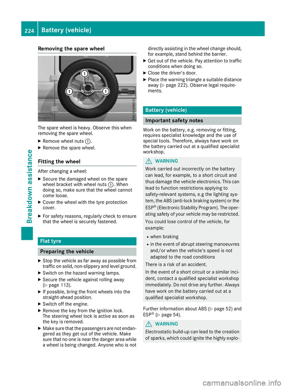
Removin
gthe spare wheel The spare wheel is heavy. Observ
ethis when
removing the spare wheel.
X Remove wheel nuts :.
X Remove the spare wheel.
Fitting the wheel After changing
awheel:
X Secure the damaged whee lonthe spare
whee lbracket with whee lnuts :.W hen
doing so, make sure tha tthe whee lcannot
come loose.
X Cover the whee lwitht he tyr eprotection
cover.
X For safety reasons ,regularly check to ensure
tha tthe whee lissecurel yfastened. Flat tyre
Preparing the vehicle
X Sto pthe vehicle as far away as possible from
traffic on solid, non-slippery and level ground.
X Switch on the hazard warning lamps.
X Secure the vehicle against rolling away
(Y page 113).
X If possible, bring the front wheels into the
straight-ahead position.
X Switch off the engine.
X Remove the key from the ignition lock.
The steering wheel lock is active as soon as
the key is removed.
X Make sure that the passengers are not endan-
gered as they get out of the vehicle. Make
sure that no one is near the danger area while
aw heel is being changed. Anyone who is not directly assisting in the wheel change should,
for example, stand behind the barrier.
X Get out of the vehicle. Pay attention to traffic
condition swhen doing so.
X Close the driver' sdoor.
X Place the warning triangle asuitable distance
away (Y page 222). Observe legal require-
ments. Batter
y(vehicle) Importan
tsafety notes
Wor kont hebattery, e.g. removing or fitting,
require sspecialist knowledge and th euse of
special tools. Therefore, always have wor kon
th eb attery carrie dout at aqualified specialist
workshop. G
WARNING
Work carried ou tincorrectly on the battery
can lead, for example, to ashort circui tand
thus damage the vehicl eelectronics. This can
leadtof unction restrictions applying to
safety-relevant systems ,e.g the lighting sys-
tem, the ABS (anti-lock braking system) or the
ESP ®
(Electronic Stability Program). The oper-
ating safety of yourv ehiclemay be restricted.
You coul dlose control of the vehicle, for
example:
R when braking
R in the event of abrupt steering manoeuvres
and/or when the vehicle's spee disnot
adapted to the road conditions
There is arisk of an accident.
In the event of ashort circui torasimilar inci-
dent, contact aqualified specialist workshop
immediately. Do not drive any further. Always have work on the battery carrie dout at a
qualified specialist workshop.
Further information about ABS (Y page52) and
ESP ®
(Y page5 4). G
WARNING
Electrostatic build-u pcan leadtot he creation
of sparks, which coul dignite the highly explo- 224
Battery (vehicle)Breakdown assistance
Page 234 of 261
X
When the vehicle is stationary, depress the
brake pedal and keep it depressed.
X Shift the transfer case to position Neutral
(Y page 125).
X Shift the automatic transmission to position
N.
X Leave the key in position 2in the ignition
lock.
X Release the brake pedal.
X Release the parking brake.
X Switc hont he hazard warning lamps
(Y page 76).
In order to signal achange of direction when
towing the vehicle with the hazard warning
lamps switched on, use the combination switch
as usual. In this case, only the turn signals for
the desired direction flash. When you reset the
combination switch, the hazard warning lamps
start flashing again.
i The automatic transmission can only
change gear when the batter yhas sufficient
charge.
If you cannot shift the automatic transmission
to position N,the propeller shafts to the
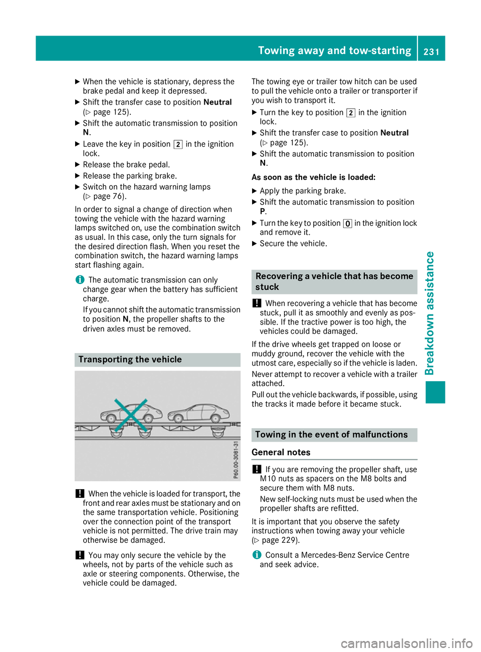
driven axles must be removed. Transporting thev
ehicle !
Whe
nthe vehicle is loadedf or transport, the
front and rear axles must be stationary and on the same transportation vehicle. Positioning
over the connection point of the transport
vehicle is not permitted. The drive train may
otherwise be damaged.
! You may only secure the vehicle by the
wheels, not by parts of the vehicle such as
axle or steering components. Otherwise, the
vehicle could be damaged. The towing eye or trailer tow hitch can be used
to pull the vehicle onto
atrailer or transporter if
you wish to transport it.
X Turn the key to position 2in the ignition
lock.
X Shift the transfer case to position Neutral
(Y page 125).
X Shift the automatic transmission to position
N.
As soon as the vehicle is loaded:
X Apply the parking brake.
X Shift the automatic transmission to position
P.
X Turn the key to position uin the ignition lock
and remove it.
X Secure the vehicle. Recovering
avehicle that has become
stuck
! Whe
nrecovering avehicl ethat ha sbecome
stuck, pull it as smoothly and evenly as pos-
sible .Ifthe tractive power is too high, the
vehicles could be damaged.
If the drive wheel sget trapped on loose or
muddy ground ,recover the vehicl ewitht he
utmost care ,especially so if the vehicl eisladen.
Neve rattempt to recover avehicl ewithat railer
attached.
Pull ou tthe vehicl ebackwards ,ifpossible ,using
the tracks it mad ebefore it became stuck. Towin
ginthe even tofm alfunctions
General notes !
If you are removing the propelle
rshaft, use
M10 nuts as spacers on the M8 bolts and
secure them with M8 nuts.
New self-locking nuts must be used when the propellers hafts are refitted.
It is important that you observe the safety
instructionsw hen towing awayy our vehicle
(Y page 229).
i Consult
aMercedes-Benz Service Centre
and seek advice. To
wing away and tow-starting
231Breakdown assis tance Z
Page 240 of 261
Drivin
gwiths ummer tyres
At temperature sbelo w+ 7† ,summer tyres lose
elasticity and therefore traction and braking
power. Change th etyres on your vehicle to
M+ Styres. Using summer tyres at ver ycold
temperature scould cause tears to form,
thereby damagin gthe tyres permanently.
Mercedes-Ben zcanno taccept responsibilit yfor
this typ eofdamage. G
WARNING
Damaged tyre scan caus etyre inflation pres-
sure loss. As aresult, you coul dlose control of
yourv ehicle. There is arisk of accident.
Check the tyres regularl yfor signs of damage
and replace any damaged tyres immediately. M+S tyres
G
WARNING
M+S tyres with atyre tread depth of less than
4mma re not suitable for use in winter as they
do not provid esufficient traction. There is a
risk of accident.
M+S tyres with atread depth of less than
4mmm ust be replaced. G
WARNING
The whee lortyre size as wellast he tyre type
of the spar ewhee land the whee ltobe
replaced may differ .Driving characteristics
can be severely impaired when you fit the
spar ewheel. There is arisk of an accident.
To prevent risks:
R adapt yourd riving style accordingly and
drive carefully
R never fit more than one spar ewhee lthat
differ sfrom the whee ltobechanged
R only use aspar ew hee lthat differ sfrom the
whee ltobec hanged for abriefp eriod
R do not switch ESP ®
off
R have aspar ew hee lofad ifferent size
replaced at the neares tqualified specialist
workshop. You must make sure that the wheel and tyre dimensions as wel
lasthe
tyr etype are correct.
Do not exceed amaximum speed of 80 km/h if
as pare wheel of adifferen tsizeisf itted.
At temperatures below +7 †, use winter tyres or all-season tyres. Bot htypes of tyr eare identified
by th eM+S marking.
Only winter tyres bearin gthe i snowflake
symbo linaddition to th eM+S marking provide
th eb est possible grip in wintry road conditions.
Only these tyres will allow driving safet ysys-
tem ssuch as AB Sand ESP ®
to function opti-
mally in winter. These tyres have been devel-
oped specifically for driving in snow.
Use M+S tyres of th esame mak eand tread on all
wheels to maintain safe handling characteris-
tics.
Always observe th emaximum permissible
speed specified for th eM+S tyres you have fit-
ted.
If you fit M+S tyres that have alower maximum
permissible speed than that of th evehicle, affix
an appropriat ewarning label in th edriver's field
of vision. This can be obtained at aqualified
specialist workshop.
When you have fitted th eM+S tyres:
X Chec kthe tyrep ressures (Y page 238).
X Restart th etyrep ressure monitor
(Y page 241). Snow chains
G
WARNING
If you drive too fas twith snow chains fitted,
they may snap. As aresult, you coul dinjure
others and damage the vehicle. There is arisk
of an accident.
Observe the maximu mpermissible spee dfor
operation with snow chains.
! Before fitting the snow chains, check them
for damage. Damaged or worn snow chains
may snap and damage the following compo-
nents:
R wheel
R whee lhousing
R whee lsuspension Winter operation
237Wheels and tyres Z
Page 241 of 261
Therefore, only use snow chains that are in
perfect condition. Observe the manufactur-
er's installation instructions.
For safety reasons, Mercedes-Benz recom-
mends that you use only snow chains that have been approved for Mercedes-Benz or that are of
an equivalent standard of quality. For more
information, please contact aqualified special-
ist workshop.
If you wish to fit snow chains, please bear the
following points in mind:
R snow chains cannot be fitted to all wheel/tyre
combinations. Observe the information
regarding permitted wheel/tyre combina-
tions (Y page 246)
R fit the snow chains on all four wheels for max-
imum tractive power and driving stability.
Snow chains must alway sbefitted in pairs; if
you only have two snow chains, fit these on
the rear wheels. The vehicle then remains
more stable under braking
R use snow chains only if the road surface is
completely snow-covered. Remove the snow
chains as soon as possible when you come to ar oad that is not snow-covered
R local regulations may restrict the use of snow
chains. Observe the appropriate regulations if you wish to fit snow chains
R do not exceed the maximum permissible
speed of 50 km/h
You may wish to deactivate ESP ®
when pulling
away with snow chains fitted (Y page 54). This
allows the wheels to spin in acontrolled manner,
achieving increased propulsive force (cut). Tyre pressure
Tyre pressur
especifications
Important safety notes G
WARNING
Underinf lated or overinflated tyres pose the
following risks:
R the tyres may burst, especially as the load
and vehicl espee dincrease.
R the tyres may weare xcessively and/or
unevenly, which may greatly impair tyre
traction.
R the driving characteristics, as wellass teer-
ing and braking, may be greatly impaired.
There is arisk of an accident.
Observe the recommende dtyre pressure and
check the tyre pressure of all the tyres includ-
ing the spar ewheel:
R at least every two weeks
R when the loadc hanges
R before embarking on alonger journey
R for changed operating conditions, e.g. off-
road driving
If necessary, correct the tyre pressure. G
WARNING
If you fit unsuitabl eaccessories onto tyre
valves, the tyre valve smay be overloadeda nd
malfunction, which can caus etyre pressure
loss. Due to their design, retrofitted tyre pres-
sure monitors keep the tyre valve open. This
can alsor esult in tyre pressure loss. There is a
risk of accident.
Only screw standar dvalve caps or valve caps
specifically provided by Mercedes-Benz for
yourv ehicleonto the tyre valve. G
WARNING
If the tyre pressure drops repeatedly ,the
wheel, valve or tyre may be damaged. Tyre
pressure that is too low may result in atyre
blow-out. There is arisk of accident. 238
Tyre pressureWheels and tyres