MERCEDES-BENZ G500 2002 W463 Owner's Manual
Manufacturer: MERCEDES-BENZ, Model Year: 2002, Model line: G500, Model: MERCEDES-BENZ G500 2002 W463Pages: 385, PDF Size: 30.37 MB
Page 261 of 385
258 What you should know at the gas station
Te ch n i c a l
data Instruments
and controlsOperationDrivingInstrument
cluster displayPractical hints Car care Index
What you should know at the gas station
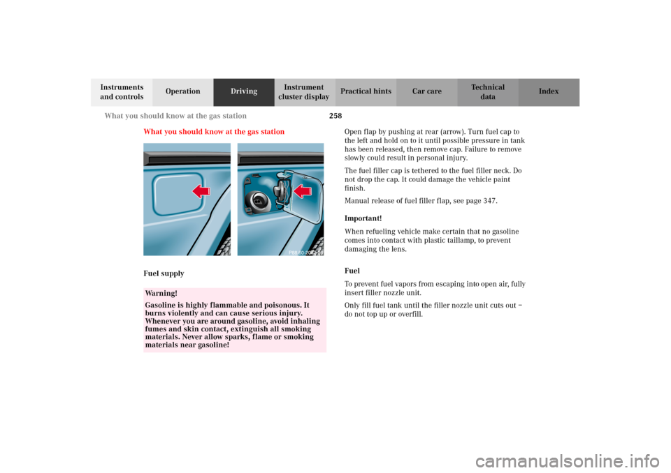
Fuel supplyOpen flap by pushing at rear (arrow). Turn fuel cap to
the left and hold on to it until possible pressure in tank
has been released, then remove cap. Failure to remove
slowly could result in personal injury.
The fuel filler cap is tethered to the fuel filler neck. Do
not drop the cap. It could damage the vehicle paint
finish.
Manual release of fuel filler flap, see page 347.
Important!
When refueling vehicle make certain that no gasoline
comes into contact with plastic taillamp, to prevent
damaging the lens.
Fuel
To prevent fuel vapors from escaping into open air, fully
insert filler nozzle unit.
Only fill fuel tank until the filler nozzle unit cuts out –
do not top up or overfill.
Wa r n i n g !
Gasoline is highly flammable and poisonous. It
burns violently and can cause serious injury.
Whenever you are around gasoline, avoid inhaling
fumes and skin contact, extinguish all smoking
materials. Never allow sparks, flame or smoking
materials near gasoline!
J_G463.book Seite 258 Mittwoch, 19. September 2001 8:06 08
Page 262 of 385
259 What you should know at the gas station
Te ch n i c a l
data Instruments
and controlsOperationDrivingInstrument
cluster displayPractical hints Car care Index Leaving the engine running and the fuel cap open can
cause the “CHECK ENGINE” lamp to illuminate.
Fuel tank capacity approximately 25.4 US gal (96.0 l).
This includes approximately 5.3 US gal (20.0 l) reserve.
Use premium unleaded gasoline: Posted Octane
Index 91 (Average of 96 RON / 86 MON).
•Engine oil
Engine oil level check, see page 127 and page 304.
Fill quantity between upper and lower dipstick
marking level: 2.1 US qt (2.0 l).
Recommended engine oils, see Approved Service
Products sheet.•Coolant
For normal replenishing, use water (potable water
quality).
For further information (e.g. anticorrosion/
antifreeze), see page 306 and 365.
• Spark plugs
Approved spark plugs, see page 360.
•Tire pressure
For tire pressure, refer to tire pressure label inside
the fuel filler flap. See page 318 for further details.
•Air conditioner
R-134a refrigerant and special PAG lubricant, see
page 363.
Wa r n i n g !
Overfilling of fuel tank may result in creating
pressure in the system which could cause a gas
discharge such as the gas spraying back out upon
removing the filler nozzle which could cause
personal injury.
J_G463.book Seite 259 Mittwoch, 19. September 2001 8:06 08
Page 263 of 385
260 What you should know at the gas station
Te ch n i c a l
data Instruments
and controlsOperationDrivingInstrument
cluster displayPractical hints Car care Index
•Bulbs
Front:
high and low beam: H4 60 / 55W 12V
fog lamp: H3 55W 12V
standing and parking lamp: T 4W 12V
turn signal lamp: PY 21W 12V (1156NA[cp 32])
Side:
side marker lamp yellow: T 4W 12V
side marker lamp red: T 4W 12V
turn signal lamp: WY 5W 12V 5W
Rear:
tail lamp: R 5W 12V
stop lamp: P 21W 12V
turn signal lamp: PY 21W 12V
backup lamp: P 21W 12V
fog lamp: P 21W 12V
license plate lamp: C 5W 12V (tubular)
J_G463.book Seite 260 Mittwoch, 19. September 2001 8:06 08
Page 264 of 385
261 Check regulary and before a long trip
Te ch n i c a l
data Instruments
and controlsOperationDrivingInstrument
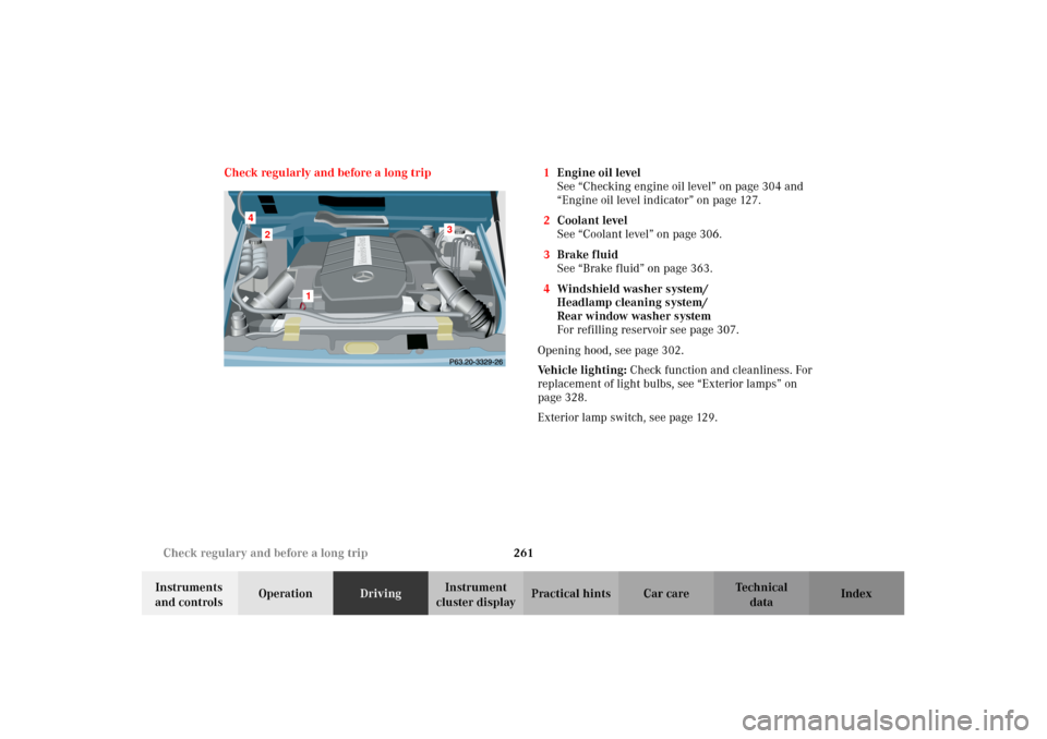
cluster displayPractical hints Car care Index Check regularly and before a long trip 1Engine oil level
See “Checking engine oil level” on page 304 and
“Engine oil level indicator” on page 127.
2Coolant level
See “Coolant level” on page 306.
3Brake fluid
See “Brake fluid” on page 363.
4Windshield washer system/
Headlamp cleaning system/
Rear window washer system
For refilling reservoir see page 307.
Opening hood, see page 302.
Vehicle lighting: Check function and cleanliness. For
replacement of light bulbs, see “Exterior lamps” on
page 328.
Exterior lamp switch, see page 129.
2
1
3
4
J_G463.book Seite 261 Mittwoch, 19. September 2001 8:06 08
Page 265 of 385

J_G463.book Seite 262 Mittwoch, 19. September 2001 8:06 08
Page 266 of 385
263 Contents - Instrument cluster display
Te ch n i c a l
data Instruments
and controlsOperation DrivingInstrument
cluster displayPractical hints Car care Index
Instrument cluster displayMalfunction and indicator
lamps in the
instrument cluster ....................264
On-board diagnostic system .........265
Check engine malfunction
indicator lamp .............................265
Brake warning lamp ..................266
Supplemental restraint system
(SRS) indicator lamp ..................267
Fuel reserve warning .................268
ABS malfunction
indicator lamp .............................269
Electronic stability program
(ESP) — warning lamp ...............270
Seat belt nonusage
warning lamp .............................270
Malfunction and indicator lamp
in the center console ................ 271
AIRBAG OFF indicator lamp ..... 271Malfunction and warning
messages in the
multifunction display .............. 272
DISPLAY DEFECTIVE
(engine control unit) ................. 273
DISPLAY DEFECTIVE
(several systems) ....................... 273
BATTERY / ALTERNATOR ........274
ANTILOCK BRAKE SYSTEM .... 275
BRAKE ASSIST ............................276
BRAKE PAD WEAR .................... 277
BRAKE FLUID ............................ 277
PARKING BRAKE ....................... 278
SEAT BELT SYSTEM .................. 278
ELEC. STABIL. PROG.
(Electronic stability program) . 279
COOLANT
(coolant level) ............................. 280
COOLANT
(coolant temperature) ............... 281
ENGINE OIL LEVEL ................... 282LIGHTING SYSTEM ....................283
LIGHT SENSOR ...........................285
DOOR ...........................................285
TRUNK OPEN .............................286
HOOD ...........................................286
TELEPHONE – FUNCTION .......287
TELE AID .....................................287
WASHER FLUID .........................288
RESTRAINT SYSTEM .................289
KEY ...............................................289
FUEL RESERVE ..........................290
UNDERVOLTAGE ........................290
ELECTRONIC BRAKE BOOSTER
(EBB) ............................................ 291
ENGINE AIR FILTER .................. 291
TC SHIFT ....................................292
TC SHIFT CONDITIONS ............292
TC IN NEUTRAL .........................293
TRANSFER CASE .......................293
J_G463.book Seite 263 Mittwoch, 19. September 2001 8:06 08
Page 267 of 385
264 Malfunction and indicator lamps
Te ch n i c a l
data Instruments
and controlsOperation DrivingInstrument
cluster displayPractical hints Car care Index
Malfunction and indicator lamps
in the instrument cluster
General information:
If a bulb in the instrument cluster fails to light up
during the bulb self-check when turning the key in
starter switch to position 2, have it checked and
replaced if necessary.
Emission control
Certain systems of the engine serve to keep the toxic
components of the exhaust gases within permissible
limits required by law.
These systems, of course, will function properly only
when maintained strictly according to factory
specifications. Any adjustments on the engine should,
therefore, be carried out only by authorized
Mercedes-Benz Light Truck Center qualified
technicians. Engine adjustments should not be altered
in any way. Moreover, the specified service jobs must be
carried out regularly according to Mercedes-Benz
servicing requirements. For details refer to the Service
Booklet.
Wa r n i n g !
Inhalation of exhaust gas is hazardous to your
health. All exhaust gas contains carbon monoxide,
and inhaling it can cause unconsciousness and
lead to death. Do not run the engine in confined areas (such as a
garage) which are not properly ventilated. If you
think that exhaust gas fumes are entering the
vehicle while driving, have the cause determined
and corrected immediately. If you must drive under
these conditions, drive only with at least one
window fully open.
J_G463.book Seite 264 Mittwoch, 19. September 2001 8:06 08
Page 268 of 385
265 Malfunction and indicator lamps
Te ch n i c a l
data Instruments
and controlsOperation DrivingInstrument
cluster displayPractical hints Car care Index On-board diagnostic system
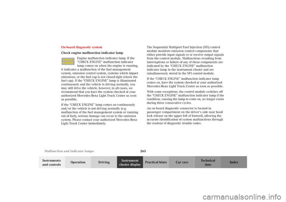
Check engine malfunction indicator lamp
Engine malfunction indicator lamp. If the
“CHECK ENGINE” malfunction indicator
lamp comes on when the engine is running,
it indicates a malfunction of the fuel management
system, emission control system, systems which impact
emissions, or the fuel cap is not closed tight (check the
fuel cap). If the “CHECK ENGINE” lamp is illuminated
continuously and the vehicle is driving normally, you
may still drive the vehicle, however, in all cases, we
recommend that you have the system checked at your
authorized Mercedes-Benz Light Truck Center as soon
as possible.
If the “CHECK ENGINE” lamp comes on continuously
and / or the vehicle is not driving normally (e.g.
malfunction of the fuel management system or running
out of fuel), serious damage can occur to the emission
system. Please contact your authorized Mercedes-Benz
Light Truck Center immediately.The Sequential Multiport Fuel Injection (SFI) control
module monitors emission control components that
either provide input signals to or receive output signals
from the control module. Malfunctions resulting from
interruptions or failure of any of these components are
indicated by the “CHECK ENGINE” malfunction
indicator lamp in the instrument cluster and are
simultaneously stored in the SFI control module.
If the “CHECK ENGINE” malfunction indicator lamp
comes on, have the system checked at your authorized
Mercedes-Benz Light Truck Center as soon as possible.
With some exceptions, the control module switches off
the “CHECK ENGINE” malfunction indicator lamp if the
condition, causing the lamp to come on, no longer exists
during three consecutive cycles.
An on-board diagnostic connector is located in
passenger compartment on the driver’s side near hood
lock release on the upper left of footwell, allowing the
accurate identification of system malfunctions through
the readout of diagnostic trouble codes.
J_G463.book Seite 265 Mittwoch, 19. September 2001 8:06 08
Page 269 of 385
266 Malfunction and indicator lamps
Te ch n i c a l
data Instruments
and controlsOperation DrivingInstrument
cluster displayPractical hints Car care Index
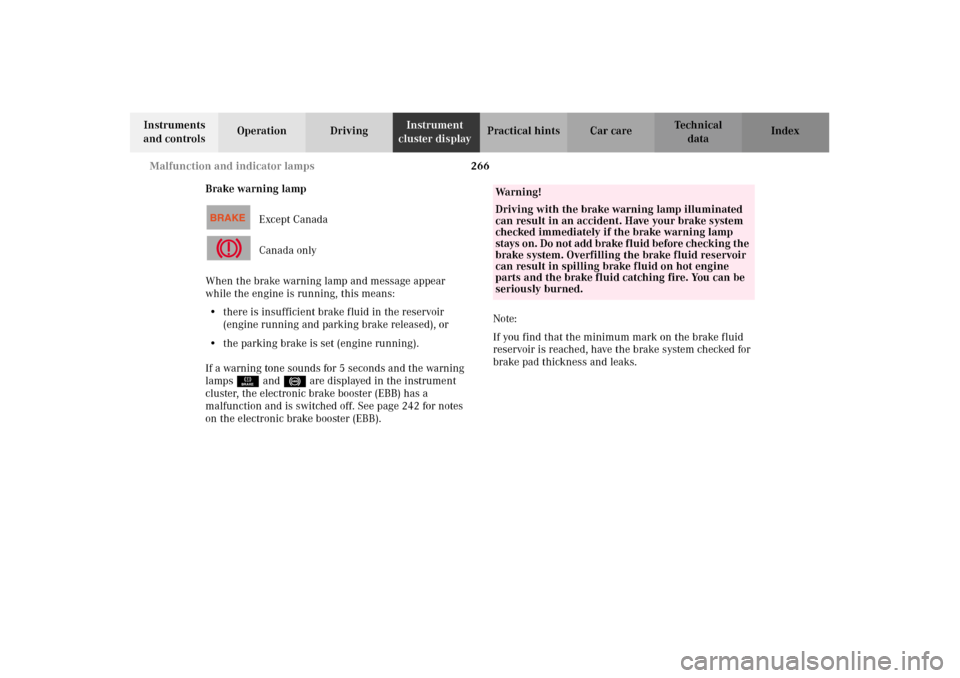
Brake warning lamp
Except Canada
Canada only
When the brake warning lamp and message appear
while the engine is running, this means:
•there is insufficient brake fluid in the reservoir
(engine running and parking brake released), or
•the parking brake is set (engine running).
If a warning tone sounds for 5 seconds and the warning
lampsÉ and - are displayed in the instrument
cluster, the electronic brake booster (EBB) has a
malfunction and is switched off. See page 242 for notes
on the electronic brake booster (EBB).Note:
If you find that the minimum mark on the brake fluid
reservoir is reached, have the brake system checked for
brake pad thickness and leaks.
Wa r n i n g !
Driving with the brake warning lamp illuminated
can result in an accident. Have your brake system
checked immediately if the brake warning lamp
stays on. Do n ot a dd b ra ke f l uid b efore check in g t he
brake system. Overfilling the brake fluid reservoir
can result in spilling brake fluid on hot engine
parts and the brake fluid catching fire. You can be
seriously burned.
J_G463.book Seite 266 Mittwoch, 19. September 2001 8:06 08
Page 270 of 385
267 Malfunction and indicator lamps
Te ch n i c a l
data Instruments
and controlsOperation DrivingInstrument
cluster displayPractical hints Car care Index Supplemental restraint system (SRS) indicator lamp
When turning the electronic key in starter
switch to position 1 the indicator lamp “SRS”
in the instrument cluster comes on. If no
fault is detected, the lamp will go out after
approximately 4 seconds.
When turning the electronic key in starter switch to
position 2 the indicator lamp “SRS” in the instrument
cluster comes on. If no fault is detected, the lamp will go
out when the engine is running.
The operational readiness of the airbag system is
verified by the indicator lamp “SRS” in the instrument
cluster when turning the electronic key in starter switch
to position 1 or 2.
After the lamp goes out, the system continues to
monitor the components and circuitry of the airbag
system and will indicate a malfunction by coming on
again.See page 66 for notes on airbags, see page 71 for belt
tensioners and page 73 for infant and child seat
restraint.
Wa r n i n g !
In the event a malfunction of the “SRS” is indicated
as outlined above, the “SRS” may not be
operational. For your safety, we strongly
recommend that you visit an authorized
Mercedes-Benz Light Truck Center immediately to
have the system checked; otherwise the “SRS” may
n ot be a ct ivated when need ed in an ac c i den t, whi ch
could result in serious or fatal injury, or it might
deploy unexpectedly and unnecessarily which
could also result in injury.
J_G463.book Seite 267 Mittwoch, 19. September 2001 8:06 08