lock MERCEDES-BENZ GLC-Class 2016 X253 Owner's Manual
[x] Cancel search | Manufacturer: MERCEDES-BENZ, Model Year: 2016, Model line: GLC-Class, Model: MERCEDES-BENZ GLC-Class 2016 X253Pages: 418, PDF Size: 9.23 MB
Page 369 of 418
XSlide coverAof positive terminal :in the direction of the arrow.
XConnect positive terminal :on your vehicle to positive terminal ;of donor battery B
using the jumper cable. Always begin with positive terminal :on your own vehicle first.
XStart the engine of the donor vehicle and run it at idling speed.
XConnect negative terminal =of donor battery Bto ground point ?of your vehicle using
the jumper cable, connecting the jumper cable to donor battery Bfirst.
XStart the engine.
XBefore disconnecting the jumper cables, let the engine run for several minutes.
XFirst, remove the jumper cables from ground point ?and negative terminal =, then from
positive clamp :and positive terminal ;. Begin each time at the contacts on your own
vehicle first.
XClose cover Aof positive clamp :after removing the jumper cables.
XHave the battery checked at a qualified specialist workshop.
Jump-starting is not considered to be a normal operating condition.
iJumper cables and further information regarding jump-starting can be obtained at any
qualified specialist workshop.
Towing and tow-starting
Important safety notes
GWARNING
Functions relevant to safety are restricted or
no longer available if:
Rthe engine is not running.
Rthe brake system or the power steering is
malfunctioning.
Rthere is a malfunction in the voltage supply or the vehicle's electrical system.
If your vehicle is being towed, much more
force may be necessary to steer or brake.
There is a risk of an accident.
In such cases, use a tow bar. Before towing,
make sure that the steering moves freely.
GWARNING
You can no longer steer the vehicle if the
steering wheel lock has been engaged. There
is a risk of an accident.
Always switch off the ignition when towing the
vehicle with a tow cable or a tow bar.
GWARNING
When towing or tow-starting another vehicle
and its weight is greater than the permissible
gross weight of your vehicle, the:
Rthe towing eye could detach itself
Rthe vehicle/trailer combination could roll-
over.
There is a risk of an accident.
When towing or tow-starting another vehicle,
its weight should not be greater than the per- missible gross weight of your vehicle.
Details on the permissible gross vehicle
weight of your vehicle can be found on the
vehicle identification plate (
Ypage 408).
!When COLLISION PREVENTION ASSIST
PLUS, DISTRONIC PLUS or the HOLD func-
tion is activated, the vehicle brakes auto-
matically in certain situations. To avoid
damage to the vehicle, deactivate these
systems in the following or similar situa-
tions:
Rwhen towing the vehicle
Rin the car wash
Towing and tow-starting367
Breakdown assistance
Z
Page 370 of 418
!Make sure that the electric parking brake
is released. If the electric parking brake is
faulty, visit a qualified specialist workshop.
!Only secure the tow rope or tow bar at the
towing eyes, or the trailer tow hitch, if avail-
able. You could otherwise damage the vehi-
cle.
!Do not use the trailer tow hitch for recov-
ery or towing. Do not use the towing eye for recovery. this could damage the vehicle. If
in doubt, have the vehicle recovered using
a crane.
!When towing, pull away slowly and
smoothly. If the tractive power is too high,
the vehicles could be damaged.
!Shift the automatic transmission to Nand
do not open the driver's or front passeng-
er's door during towing. The automatic
transmission may otherwise shift to posi-
tion P, which could damage the transmis-
sion.
!Do not tow with sling-type equipment.
This could damage the vehicle.
!The vehicle can be towed a maximum of
30 miles (50km). The towing speed of
30 mph (50 km/h) must not be exceeded.
If the vehicle has to be towed more than
30 miles (50km), the entire vehicle must be
raised and transported.
It is better to have the vehicle transported
than to have it towed away.
If the vehicle has suffered transmission dam-
age, have it transported on a transporter or
trailer.
The automatic transmission must be in posi-
tion Nwhen the vehicle is being towed. If the
automatic transmission cannot be shifted to
position N, have the vehicle transported on a
transporter or trailer. The battery must be connected and charged.
Otherwise, you:
Rcannot turn the SmartKey to position
2in
the ignition lock
Rcannot release the electric parking brake
Rcannot shift the automatic transmission to
position N
Disarm the automatic locking feature before
the vehicle is towed (
Ypage 90). You could
otherwise be locked out when pushing or
towing the vehicle.
Installing/removing the towing eye
Installing the towing eye
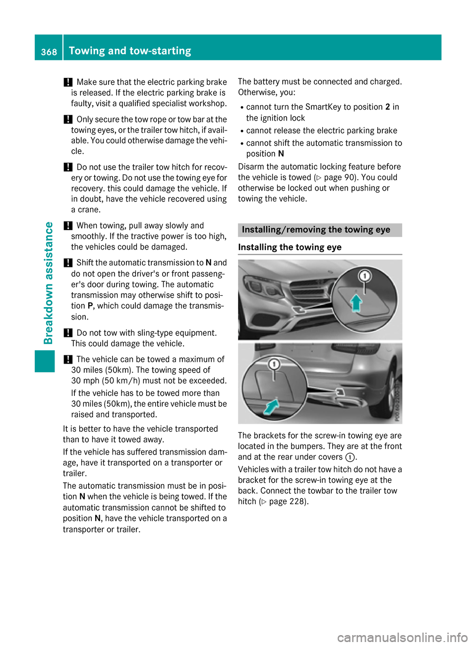
The brackets for the screw-in towing eye are
located in the bumpers. They are at the front
and at the rear under covers :.
Vehicles with a trailer tow hitch do not have a
bracket for the screw-in towing eye at the
back. Connect the towbar to the trailer tow
hitch (
Ypage 228).
368Towing and tow-starting
Breakdown assistance
Page 371 of 418
XRemove thetowin geye from th eleft-han d
stowage well under th ecargo compartmen t
floor (
Ypage 355).
XPress th emar kon cover :inward sand
remove .
XScrew in th etowin geye clockwise as far as
it will go and tighten it .
Removingth etowing eye
XUnscrew and remove th etowin geye.
XAttac hcover :to th ebumper and press
until it engages.
XPut th etowin geye bac kinto th evehicl e
tool kit.
Towing a vehicle wit hbot haxles on
th egroun d
The automatic transmission automatically
shiftsto position Pwhen you open th edriver's
or front-passenger doo ror when you remove
th eSmartKey from th eignition lock. In order
to ensur ethat th eautomatic transmission
stays in position Nwhen towin gth evehicle,
you mus tobserv eth efollowin gpoints :
XMakesur ethat th evehicl eis stationary.
XTurn th eSmartKey to position 2in th eigni-
tion lock.
XDepress and hold th ebrak epedal .
XShift th eautomatic transmission to posi-
tion N.
XLeav eth eSmartKey in position 2in th e
ignition lock.
XReleas eth ebrak epedal .
XReleas eth eelectric parkin gbrake.
XSwitc hon th ehazard warnin glamp s
(
Ypage 127).
In order to signal achang eof direction when
towin gth evehicl ewit hth ehazard warnin g
lamp sswitched on ,use th ecombination
switch as usual. In this case, only th eindica-
to rlamp sfor th edirection of travel flash. Afte
rresetting th ecombination switch ,th e
hazard warnin glamp start sflashin gagain .
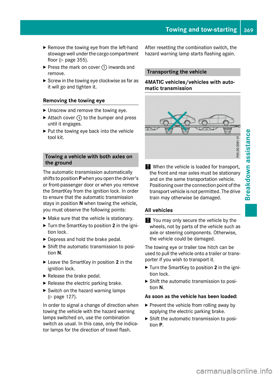
Transporting th e vehicle
4MATIC vehicles/vehicles wit hauto-
mati ctransmission
!Whe nth evehicl eis loade dfor transport,
th efron tand rear axles mus tbe stationary
and on th esam etransportation vehicle.
Positionin gove rth econnection poin tof th e
transpor tvehicl eis no tpermitted. The drive
train may otherwise be damaged.
All vehicles
!You may only secure th evehicl eby th e
wheels, no tby part sof th evehicl esuc has
axl eor steerin gcomponents. Otherwise ,
th evehicl ecould be damaged.
The towin geye or trailer to whitch can be
used to pull th evehicl eonto atrailer or trans -
porte rif you wish to transpor tit.
XTurn th eSmartKey to position 2in th eigni-
tion lock.
XShift th eautomatic transmission to posi-
tion N.
As soon as th evehicle ha sbeen loaded:
XPreven tth evehicl efrom rollin gaway by
applyin gth eelectric parkin gbrake.
XShift th eautomatic transmission to posi-
tion P.
Towing and tow-starting369
Breakdown assistance
Z
Page 372 of 418
XTurn the SmartKey to position0in the igni-
tion lock and remove it.
XSecure the vehicle.
Notes on 4MATIC vehicles
!
Vehicles with 4MATIC must not be towed
with either the front or the rear axle raised,
as doing so will damage the transmission.
Vehicles with 4MATIC may either be towed
away with both axles on the ground or be loa- ded up and transported.
If the vehicle's transmission, front, or rear
axle is damaged, have the vehicle transported
on a truck or trailer.
In the event of damage to the electrical
system: if the battery is defective, the auto-
matic transmission will be locked in position
P. To shift the automatic transmission to posi-
tion N, you must provide power to the vehi-
cle's electrical system in the same way as
when jump-starting (
Ypage 365).
Have the vehicle transported on a transporter
or trailer.
Tow-starting (emergency engine
starting)
!
Vehicles with automatic transmission
must not be tow-started. You could other-
wise damage the automatic transmission.
iYou can find information on "Jump-start-
ing" under (
Ypage 365).
Fuses
Important safety notes
GWARNING
If you manipulate or bridge a faulty fuse or if
you replace it with a fuse with a higher amper- age, the electric cables could be overloaded.
This could result in a fire. There is a risk of an
accident and injury.
Always replace faulty fuses with the specifiednew fuses having the correct amperage.
Blown fuses must be replaced with fuses of
the same rating, which you can recognize by
the color and value. The fuse ratings are listed
in the fuse allocation chart.
If a newly inserted fuse also blows, have the
cause traced and rectified at a qualified spe-
cialist workshop, e.g. an authorized
Mercedes-Benz Center.
!Only use fuses that have been approved
for Mercedes-Benz vehicles and which
have the correct fuse rating for the system concerned. Otherwise, components or sys-
tems could be damaged.
The fuses in your vehicle serve to close down
faulty circuits. If a fuse blows, all the compo-
nents on the circuit and their functions stop
operating.
Before changing a fuse
Observe the important safety notes
(
Ypage 370)
XSecure the vehicle against rolling away
(
Ypage 172).
XSwitch off the engine.
XSwitch off all electrical consumers.
XRemove the SmartKey from the ignition
lock.
or, in vehicles with KEYLESS-GO start-func-
tion or KEYLESS ‑GO
XOpen the driver's door.
The on-board electronics now have status
0. This is the same as the SmartKey having
been removed.
The driver’s door can be closed again.
All indicator lamps in the instrument cluster
must be off.
The fuses are located in various fuse boxes:
RFuse box on the driver's side of the dash-
board
RFuse box in the front-passenger footwell
370Fuses
Breakdown assistance
Page 377 of 418
When parking your vehicle, make sure that
the tires do not get deformed by the curb or
other obstacles. If they cannot be avoided,
drive over obstacles such as curbs slowly and
at an obtuse angle. Otherwise, you may dam-
age the wheels or tires.
Regular checking of wheels and tires
GWARNING
Damaged tires can cause tire inflation pres-
sure loss. As a result, you could lose control of
your vehicle. There is a risk of accident.
Check the tires regularly for signs of damage
and replace any damaged tires immediately.
Check wheels and tires for damage at least
once a month. Check wheels and tires after
driving off-road or on rough roads. Damaged
wheels can cause a loss of tire pressure. Pay
particular attention to damage such as:
Rcuts in the tires
Rpunctures
Rtears in the tires
Rbulges on tires
Rdeformation or severe corrosion on wheels
Regularly check the tire tread depth and the
condition of the tread across the whole width
of the tire (
Ypage 375). If necessary, turn the
front wheels to full lock in order to inspect the
inner side of the tire surface.
All wheels must have a valve cap to protect
the valve against dirt and moisture. Do not
mount anything onto the valve other than the
standard valve cap or other valve caps
approved by Mercedes-Benz for your vehicle.
Do not use any other valve caps or systems,
e.g. tire pressure monitoring systems.
Regularly check the pressure of all the tires
particularly prior to long trips. Adjust the tire
pressure as necessary (
Ypage 377). The service life of tires depends, among other
things, on the following factors:
Rdriving style
Rtire pressure
Rdistance covered
Notes on tire tread
GWARNING
Insufficient tire tread will reduce tire traction.
The tire is no longer able to dissipate water.
This means that on wet road surfaces, the risk
of hydroplaning increases, in particular where speed is not adapted to suit the driving con-
ditions. There is a risk of accident.
If the tire pressure is too high or too low, tires
may exhibit different levels of wear at differ-
ent locations on the tire tread. Thus, you
should regularly check the tread depth and
the condition of the tread across the entire
width of all tires.
Minimum tire tread depth for:
RSummer tires: âin (3 mm)
RM+S tires: ãin (4 mm)
For safety reasons, replace the tires before
the legally prescribed limit for the minimum
tire tread depth is reached.
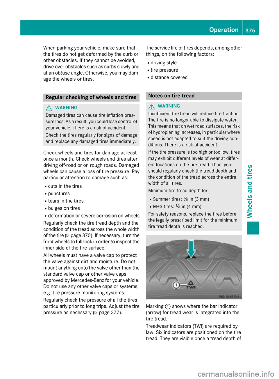
Marking :shows where the bar indicator
(arrow) for tread wear is integrated into the
tire tread.
Treadwear indicators (TWI) are required by
law. Six indicators are positioned on the tire
tread. They are visible once a tread depth of
Operation375
Wheels and tires
Z
Page 385 of 418
Checking the tire pressure electroni-
cally
XMake sure that the SmartKey is in position2 in the ignition lock (
Ypage 153).
XUse ò on the steering wheel to call up
the list of menus.
XPress 9or: on the steering wheel
to select the Service
menu.
XPress theabutton.
XPress 9or: to select Tire Pres‐
sure.
XPress the abutton.
The current tire pressure of each tire is
shown in the multifunction display.
If the vehicle was parked for longer than
20 minutes, the following message appears:
Tire pressure will be displayed
after driving a few minutes.
After a teach-in process, the tire pressure
monitor automatically detects new wheels or
new sensors. As long as a clear allocation of
the tire pressure value to the individual
wheels is not possible, the Tire Pressure
Monitor Activemessage is shown instead
of the tire pressure display. The tire pressures are already being monitored.
Tire pressure monitor warning mes-
sages
If the tire pressure monitor detects a pressure
loss in one or more tires, a warning message
is shown in the multifunction display. The yel- low tire pressure warning lamp then lights up.
RIf the Please Correct Tire Pressure
message appears in the multifunction dis-
play, the tire pressure in at least one tire is
too low. The tire pressure must be correc-
ted when the opportunity arises.
RIf theCheckTiresmessage appears in the
multifunction display, the tire pressure in at
least one tire has dropped significantly. The
tires must be checked.
RIf the Warning Tire Malfunctionmes-
sage appears in the multifunction display, the tire pressure in at least one tire has
dropped suddenly. The tires must be
checked.
Observe the instructions and safety notes in
the display messages in the "Tires" section
(
Ypage 285).
If the wheel positions on the vehicle are rota-
ted, the tire pressures may be displayed for
the wrong positions for a short time. This is
rectified after a few minutes of driving, and
the tire pressures are displayed for the cor-
rect positions.
Restarting the tire pressure monitor
When you restart the tire pressure monitor, all
existing warning messages are deleted and
the warning lamps go out. The monitor uses
the currently set tire pressures as the refer-
ence values for monitoring. In most cases, the tire pressure monitor will automatically
detect the new reference values after you
have changed the tire pressure. However, you
can also define reference values manually as
described here. The tire pressure monitor
then monitors the new tire pressure values.
XSet the tire pressure to the value recom-
mended for the corresponding driving sit-
uation on the Tire and Loading Informationplacard on the driver's side
B-pillar (
Ypage 377).
You can find more tire pressure values for
various operating conditions in the tire
pressure table inside the fuel filler flap
(
Ypage 377).
XMake sure that the tire pressure is correct
on all four wheels.
XMake sure that the SmartKey is in position 2 in the ignition lock (
Ypage 153).
XUse ò on the steering wheel to call up
the list of menus.
XPress 9or: on the steering wheel
to select the Service
menu.
XPress theabutton.
XPress 9or: to select Tire Pres‐
sure.
Tire pressure383
Wheels and tires
Z
Page 398 of 418
XShift the transmission to positionP.
XMake sure that the vehicle level is set to
"Normal" on vehicles with AIR BODY CON-
TROL (
Ypage 196).
XSwitch off the engine.
XVehicles without KEYLESS-GO:remove
the SmartKey from the ignition lock.
XVehicles with KEYLESS-GO start-func-
tion or KEYLESS-GO: open the driver's
door.
The on-board electronics now have status
0 . This is the same as the SmartKey having
been removed.
XVehicles with KEYLESS-GO start-func-
tion or KEYLESS-GO: remove the Start/
Stop button from the ignition lock
(
Ypage 153).
XMake sure that the engine cannot be star-
ted via your smartphone (
Ypage 156).
XIf included in the vehicle equipment,
remove the tire-change tool kit from the
vehicle.
XSafeguard the vehicle against rolling away.
Securing the vehicle to prevent it from
rolling away
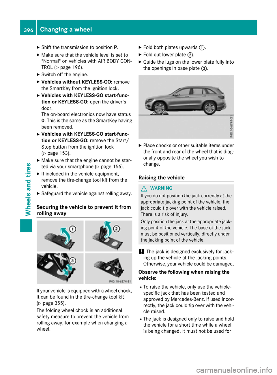
If your vehicle is equipped with a wheel chock,
it can be found in the tire-change tool kit
(
Ypage 355).
The folding wheel chock is an additional
safety measure to prevent the vehicle from
rolling away, for example when changing a
wheel.
XFold both plates upwards :.
XFold out lower plate;.
XGuide the lugs on the lower plate fully into
the openings in base plate =.
XPlace chocks or other suitable items under
the front and rear of the wheel that is diag-
onally opposite the wheel you wish to
change.
Raising the vehicle
GWARNING
If you do not position the jack correctly at the
appropriate jacking point of the vehicle, the
jack could tip over with the vehicle raised.
There is a risk of injury.
Only position the jack at the appropriate jack-
ing point of the vehicle. The base of the jack
must be positioned vertically, directly under
the jacking point of the vehicle.
!The jack is designed exclusively for jack-
ing up the vehicle at the jacking points.
Otherwise, your vehicle could be damaged.
Observe the following when raising the
vehicle:
RTo raise the vehicle, only use the vehicle-
specific jack that has been tested and
approved by Mercedes-Benz. If used incor-
rectly, the jack could tip over with the vehi- cle raised.
RThe jack is designed only to raise and hold
the vehicle for a short time while a wheel
is being changed. It must not be used for
396Changing a wheel
Wheels and tires
Page 399 of 418
performing maintenance work under the
vehicle.
RAvoid changing the wheel on uphill and
downhill slopes.
RBefore raising the vehicle, secure it from
rolling away by applying the parking brake
and inserting wheel chocks. Do not disen-
gage the parking brake while the vehicle is
raised.
RThe jack must be placed on a firm, flat and
non-slip surface. On a loose surface, a
large, flat, load-bearing underlay must be
used. On a slippery surface, a non-slip
underlay must be used, e.g. rubber mats.
RDo not use wooden blocks or similar
objects as a jack underlay. Otherwise, the
jack will not be able to achieve its load-
bearing capacity due to the restricted
height.
RMake sure that the distance between the
underside of the tires and the ground does
not exceed 1.2 in (3 cm).
RNever place your hands and feet under the
raised vehicle.
RDo not lie under the vehicle.
RDo not start the engine when the vehicle is
raised.
RNever open or close a door or the tailgate
when the vehicle is raised.
RMake sure that no persons are present in
the vehicle when the vehicle is raised.
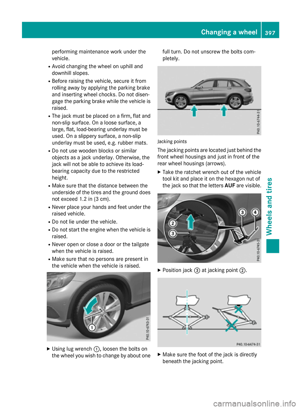
XUsing lug wrench :, loosen the bolts on
the wheel you wish to change by about one full turn. Do not unscrew the bolts com-
pletely.
Jacking points
The jacking points are located just behind the
front wheel housings and just in front of the
rear wheel housings (arrows).
XTake the ratchet wrench out of the vehicle
tool kit and place it on the hexagon nut of
the jack so that the letters AUFare visible.
XPosition jack =at jacking point ;.
XMake sure the foot of the jack is directly
beneath the jacking point.
Changing a wheel397
Wheels and tires
Z
Page 401 of 418

Lowering the vehicle
GWARNING
The wheels could work loose if the wheel nuts and bolts are not tightened to the specified
tightening torque. There is a risk of accident.
Have the tightening torque immediately
checked at a qualified specialist workshop
after a wheel is changed.
XTurn the crank of the jack counter-clock-
wise until the vehicle is once again standing
firmly on the ground.
XPlace the jack to one side.
XTighten the wheel bolts evenly in a cross-
wise pattern in the sequence indicated ( :
to A). The specified tightening torque is
96 lb-f t(130 Nm).
XTurn the jack back to its initial position.
XStow the jack and the rest of the tire-
change tool kit in the cargo compartment
again.
XCheck the tire pressure of the newly moun-
ted wheel and adjust it if necessary.
Observe the recommended tire pressure
(
Ypage 377).
When you are driving with the emergency
spare wheel mounted, the tire pressure mon-
itor cannot function reliably. Only restart the
tire pressure monitor when the defective
wheel has been replaced with a new wheel.
All mounted wheels must be equipped with
functioning sensors for the tire pressure mon-
itor.
Wheel and tire combinations
General notes
!
For safety reasons, Mercedes-Benz rec-
ommends that you only use tires and
wheels which have been approved by
Mercedes-Benz specifically for your vehi-
cle.
These tires have been specially adapted for
use with the control systems, such as ABS
or ESP
®, and are marked as follows:
RMO = Mercedes-Benz Original
RMOE = Mercedes-Benz Original Extended
(tires featuring run-flat characteristics)
RMO1 = Mercedes-Benz Original (only cer-
tain AMG tires)
Mercedes-Benz Original Extended tires
may only be used on wheels that have been
specifically approved by Mercedes-Benz.
Only use tires, wheels or accessories tes-
ted and approved by Mercedes-Benz. Cer-
tain characteristics, e.g. handling, vehicle
noise emissions or fuel consumption, may
otherwise be adversely affected. In addi-
tion, when driving with a load, tire dimen-
sion variations could cause the tires to
come into contact with the bodywork and
axle components. This could result in dam-
age to the tires or the vehicle.
Mercedes-Benz accepts no liability for
damage resulting from the use of tires,
wheels or accessories other than those tes-
ted and approved.
Information on tires, wheels and approved
combinations can be obtained from any
qualified specialist workshop.
!Retreaded tires are neither tested nor rec-
ommended by Mercedes-Benz, since pre-
vious damage cannot always be detected
on retreaded tires. As a result, Mercedes-
Benz cannot guarantee vehicle safety if
retreaded tires are mounted. Do not mount
used tires if you have no information about
their previous usage.
Wheel and tire combinations399
Wheels and tires
Z
Page 416 of 418

!Do not add distilled or de-ionized water to
the washer fluid container. Otherwise, the
level sensor may be damaged.
!Only MB SummerFit and MB WinterFit
washer fluid should be mixed together. The spray nozzles may otherwise become
blocked.
When handling washer fluid, observe the
important safety notes on service products
(
Ypage 409).
At temperatures above freezing:
XFill the washer fluid reservoir with a mixture
of water and windshield washer fluid, e.g.
MB SummerFit.
Add 1 part MB SummerFit to 100 parts water.
At temperatures below freezing:
XFill the washer fluid reservoir with a mixture of water and washer fluid, e.g. MB Winter-
Fit.
For the correct mixing ratio refer to the
information on the antifreeze reservoir.
iAdd windshield washer fluid, e.g. MB
SummerFit or MB WinterFit, to the washer
fluid all year round.
Climate control system refrigerant
Important safety notes
The climate control system of your vehicle is
filled with refrigerant R‑134a.
The instruction label regarding the refrigerant
type used can be found on the radiator cross
member.
!Only the refrigerant R‑134a and the PAG
oil approved by Mercedes-Benz may be
used. The approved PAG oil may not be
mixed with any other PAG oil that is not
approved for R-134a refrigerant. Other-
wise, the climate control system may be
damaged.
Service work, such as topping up refrigerant
or replacing components, may only be carried out by a qualified specialist workshop. All
applicable regulations must be adhered to,
SAE standard J639 included.
Always have work on the climate control sys-
tem carried out at a qualified specialist work-
shop.
Refrigerant instruction label
Example: refrigerant instruction label
:
Warning symbol
;Refrigerant filling capacity
=Applicable standards
?PAG oil part number
AType of refrigerant
Warning symbol :advises you about:
Rpossible dangers
Rhaving service work carried out at a quali-
fied specialist workshop
Filling capacities
All models
Refrigerant22.2 ± 0.4 oz
(630 ± 10 g)
PAG oil2.8 oz
(80 g)
414Service products and filling capacities
Technical data