ECU MERCEDES-BENZ GLC-Class 2016 X253 Manual Online
[x] Cancel search | Manufacturer: MERCEDES-BENZ, Model Year: 2016, Model line: GLC-Class, Model: MERCEDES-BENZ GLC-Class 2016 X253Pages: 418, PDF Size: 9.23 MB
Page 368 of 418
Do not start the vehicle using a rapid charging device. If your vehicle's battery is discharged,
the engine can be jump-started from another vehicle or from a second battery using jumper
cables. Observe the following points:
RThe battery is not accessible in all vehicles. If the other vehicle's battery is not accessible,
jump-start the vehicle using a second battery or a jump-starting device.
RYou may only jump-start the vehicle when the engine and exhaust system are cold.
ROnly jump-start from batteries with a 12 V voltage rating.
ROnly use jumper cables which have a sufficient cross-section and insulated terminal clamps.
RIf the battery is fully discharged, leave the battery that is being used to jump-start connected
for a few minutes before attempting to start. This charges the battery slightly.
RMake sure that the two vehicles do not touch.
Make sure that:
Rthe jumper cables are not damaged.
Rwhen the jumper cables are connected to the battery, uninsulated sections of the terminal
clamp do not come into contact with other metal sections.
Rthe jumper cables cannot come into contact with parts which can move when the engine is
running, such as the V-belt pulley or the fan.
XSecure the vehicle by applying the electric parking brake.
XShift the transmission to position P.
XMake sure that the ignition is switched off (Ypage 153). All indicator lamps in the instrument
cluster must be off. When using the SmartKey, turn the SmartKey to position 0in the ignition
lock and remove it (
Ypage 153).
XSwitch off all electrical consumers, e.g. rear window defroster, lighting, etc.
XOpen the hood.
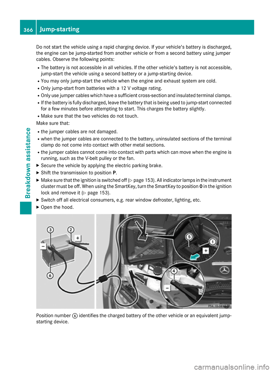
Position number Bidentifies the charged battery of the other vehicle or an equivalent jump-
starting device.
366Jump-starting
Breakdown assistance
Page 370 of 418
!Make sure that the electric parking brake
is released. If the electric parking brake is
faulty, visit a qualified specialist workshop.
!Only secure the tow rope or tow bar at the
towing eyes, or the trailer tow hitch, if avail-
able. You could otherwise damage the vehi-
cle.
!Do not use the trailer tow hitch for recov-
ery or towing. Do not use the towing eye for recovery. this could damage the vehicle. If
in doubt, have the vehicle recovered using
a crane.
!When towing, pull away slowly and
smoothly. If the tractive power is too high,
the vehicles could be damaged.
!Shift the automatic transmission to Nand
do not open the driver's or front passeng-
er's door during towing. The automatic
transmission may otherwise shift to posi-
tion P, which could damage the transmis-
sion.
!Do not tow with sling-type equipment.
This could damage the vehicle.
!The vehicle can be towed a maximum of
30 miles (50km). The towing speed of
30 mph (50 km/h) must not be exceeded.
If the vehicle has to be towed more than
30 miles (50km), the entire vehicle must be
raised and transported.
It is better to have the vehicle transported
than to have it towed away.
If the vehicle has suffered transmission dam-
age, have it transported on a transporter or
trailer.
The automatic transmission must be in posi-
tion Nwhen the vehicle is being towed. If the
automatic transmission cannot be shifted to
position N, have the vehicle transported on a
transporter or trailer. The battery must be connected and charged.
Otherwise, you:
Rcannot turn the SmartKey to position
2in
the ignition lock
Rcannot release the electric parking brake
Rcannot shift the automatic transmission to
position N
Disarm the automatic locking feature before
the vehicle is towed (
Ypage 90). You could
otherwise be locked out when pushing or
towing the vehicle.
Installing/removing the towing eye
Installing the towing eye
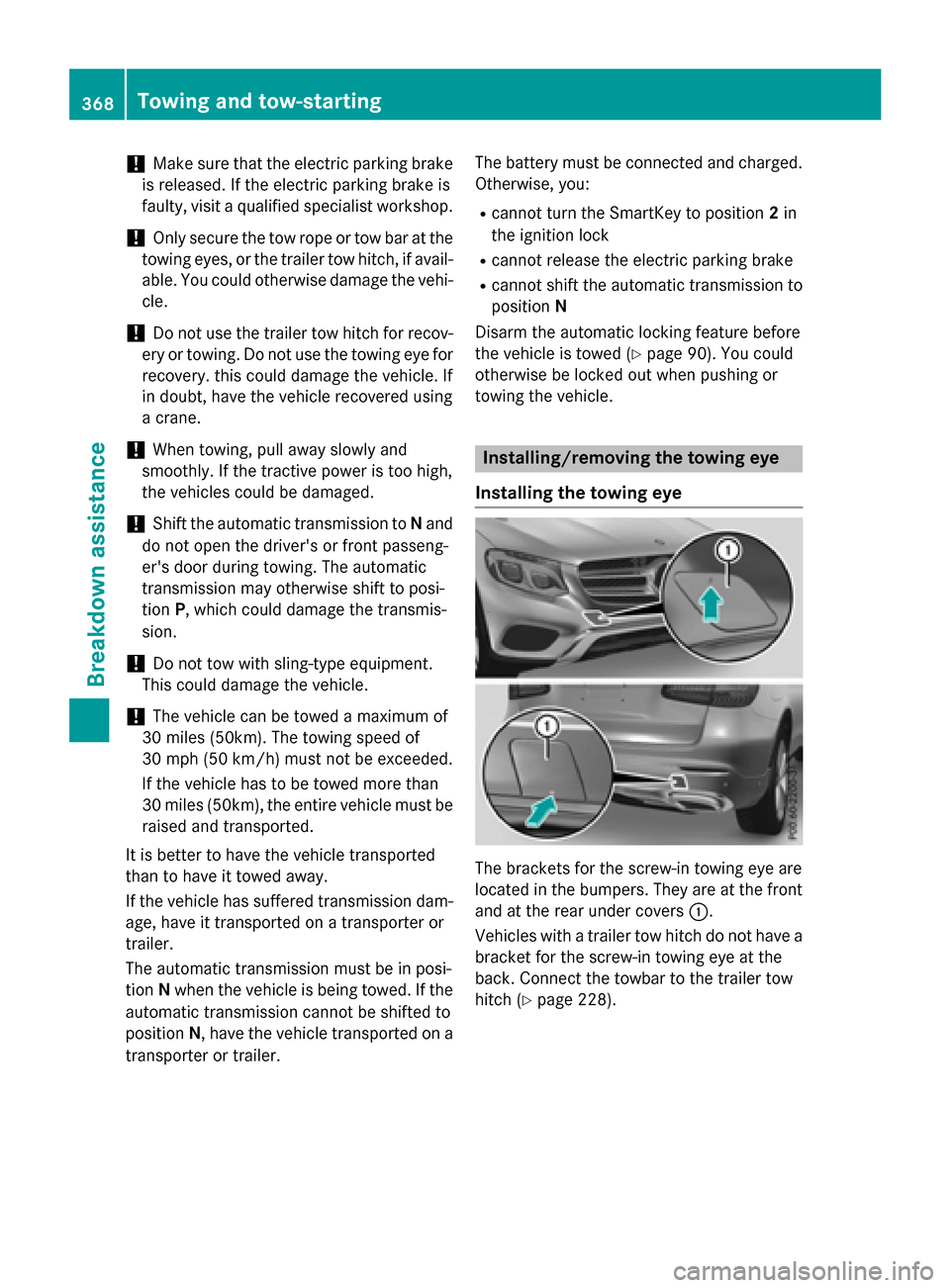
The brackets for the screw-in towing eye are
located in the bumpers. They are at the front
and at the rear under covers :.
Vehicles with a trailer tow hitch do not have a
bracket for the screw-in towing eye at the
back. Connect the towbar to the trailer tow
hitch (
Ypage 228).
368Towing and tow-starting
Breakdown assistance
Page 371 of 418
XRemove thetowin geye from th eleft-han d
stowage well under th ecargo compartmen t
floor (
Ypage 355).
XPress th emar kon cover :inward sand
remove .
XScrew in th etowin geye clockwise as far as
it will go and tighten it .
Removingth etowing eye
XUnscrew and remove th etowin geye.
XAttac hcover :to th ebumper and press
until it engages.
XPut th etowin geye bac kinto th evehicl e
tool kit.
Towing a vehicle wit hbot haxles on
th egroun d
The automatic transmission automatically
shiftsto position Pwhen you open th edriver's
or front-passenger doo ror when you remove
th eSmartKey from th eignition lock. In order
to ensur ethat th eautomatic transmission
stays in position Nwhen towin gth evehicle,
you mus tobserv eth efollowin gpoints :
XMakesur ethat th evehicl eis stationary.
XTurn th eSmartKey to position 2in th eigni-
tion lock.
XDepress and hold th ebrak epedal .
XShift th eautomatic transmission to posi-
tion N.
XLeav eth eSmartKey in position 2in th e
ignition lock.
XReleas eth ebrak epedal .
XReleas eth eelectric parkin gbrake.
XSwitc hon th ehazard warnin glamp s
(
Ypage 127).
In order to signal achang eof direction when
towin gth evehicl ewit hth ehazard warnin g
lamp sswitched on ,use th ecombination
switch as usual. In this case, only th eindica-
to rlamp sfor th edirection of travel flash. Afte
rresetting th ecombination switch ,th e
hazard warnin glamp start sflashin gagain .
Transporting th e vehicle
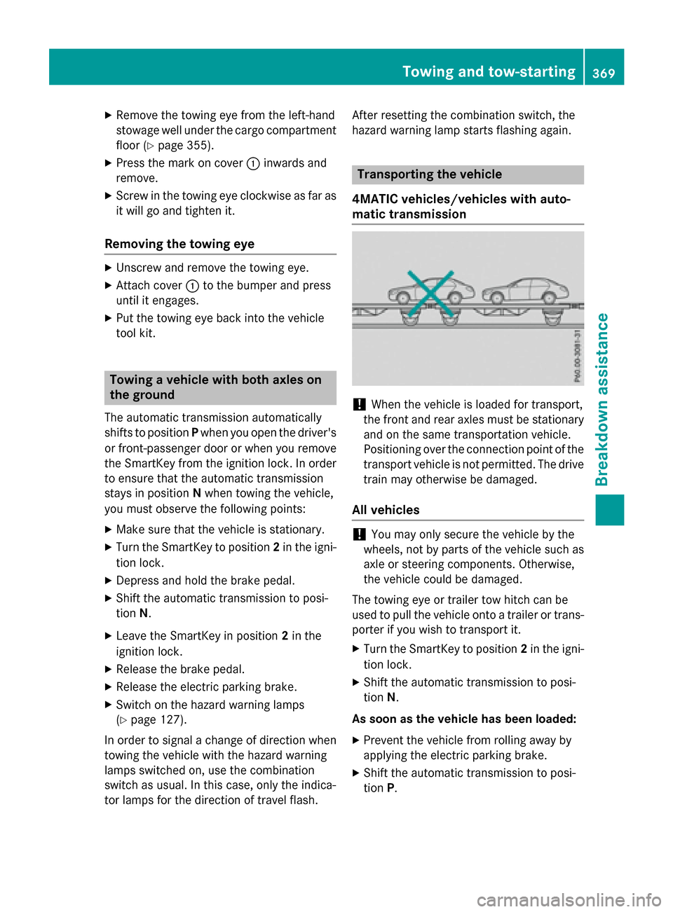
4MATIC vehicles/vehicles wit hauto-
mati ctransmission
!Whe nth evehicl eis loade dfor transport,
th efron tand rear axles mus tbe stationary
and on th esam etransportation vehicle.
Positionin gove rth econnection poin tof th e
transpor tvehicl eis no tpermitted. The drive
train may otherwise be damaged.
All vehicles
!You may only secure th evehicl eby th e
wheels, no tby part sof th evehicl esuc has
axl eor steerin gcomponents. Otherwise ,
th evehicl ecould be damaged.
The towin geye or trailer to whitch can be
used to pull th evehicl eonto atrailer or trans -
porte rif you wish to transpor tit.
XTurn th eSmartKey to position 2in th eigni-
tion lock.
XShift th eautomatic transmission to posi-
tion N.
As soon as th evehicle ha sbeen loaded:
XPreven tth evehicl efrom rollin gaway by
applyin gth eelectric parkin gbrake.
XShift th eautomatic transmission to posi-
tion P.
Towing and tow-starting369
Breakdown assistance
Z
Page 372 of 418
XTurn the SmartKey to position0in the igni-
tion lock and remove it.
XSecure the vehicle.
Notes on 4MATIC vehicles
!
Vehicles with 4MATIC must not be towed
with either the front or the rear axle raised,
as doing so will damage the transmission.
Vehicles with 4MATIC may either be towed
away with both axles on the ground or be loa- ded up and transported.
If the vehicle's transmission, front, or rear
axle is damaged, have the vehicle transported
on a truck or trailer.
In the event of damage to the electrical
system: if the battery is defective, the auto-
matic transmission will be locked in position
P. To shift the automatic transmission to posi-
tion N, you must provide power to the vehi-
cle's electrical system in the same way as
when jump-starting (
Ypage 365).
Have the vehicle transported on a transporter
or trailer.
Tow-starting (emergency engine
starting)
!
Vehicles with automatic transmission
must not be tow-started. You could other-
wise damage the automatic transmission.
iYou can find information on "Jump-start-
ing" under (
Ypage 365).
Fuses
Important safety notes
GWARNING
If you manipulate or bridge a faulty fuse or if
you replace it with a fuse with a higher amper- age, the electric cables could be overloaded.
This could result in a fire. There is a risk of an
accident and injury.
Always replace faulty fuses with the specifiednew fuses having the correct amperage.
Blown fuses must be replaced with fuses of
the same rating, which you can recognize by
the color and value. The fuse ratings are listed
in the fuse allocation chart.
If a newly inserted fuse also blows, have the
cause traced and rectified at a qualified spe-
cialist workshop, e.g. an authorized
Mercedes-Benz Center.
!Only use fuses that have been approved
for Mercedes-Benz vehicles and which
have the correct fuse rating for the system concerned. Otherwise, components or sys-
tems could be damaged.
The fuses in your vehicle serve to close down
faulty circuits. If a fuse blows, all the compo-
nents on the circuit and their functions stop
operating.
Before changing a fuse
Observe the important safety notes
(
Ypage 370)
XSecure the vehicle against rolling away
(
Ypage 172).
XSwitch off the engine.
XSwitch off all electrical consumers.
XRemove the SmartKey from the ignition
lock.
or, in vehicles with KEYLESS-GO start-func-
tion or KEYLESS ‑GO
XOpen the driver's door.
The on-board electronics now have status
0. This is the same as the SmartKey having
been removed.
The driver’s door can be closed again.
All indicator lamps in the instrument cluster
must be off.
The fuses are located in various fuse boxes:
RFuse box on the driver's side of the dash-
board
RFuse box in the front-passenger footwell
370Fuses
Breakdown assistance
Page 383 of 418
Checking tire pressures manually
To determine and set the correct tire pres-
sure, proceed as follows:
XRemove the valve cap of the tire that is to
be checked.
XPress the tire pressure gauge securely onto
the valve.
XRead the tire pressure and compare it to
the recommended value on the Tire and
Loading Information placard or the tire
pressure table (
Ypage 377).
XIf the tire pressure is too low, increase the
tire pressure to the recommended value.
XIf the tire pressure is too high, release air.
To do so, press down the metal pin in the
valve, using the tip of a pen for example.
Then check the tire pressure again using
the tire pressure checker.
XScrew the valve cap onto the valve.
XRepeat these steps for the other tires.
Tire pressure monitor
General notes
If a tire pressure monitor is installed, the vehi-
cle's wheels have sensors that monitor the
tire pressures in all four tires. The tire pres-
sure monitor warns you if the pressure drops
in one or more of the tires. The tire pressure
monitor only functions if the corresponding
sensors are installed in all wheels.
Information on tire pressures is displayed in
the multifunction display. After a few minutes
of driving, the current tire pressure of each
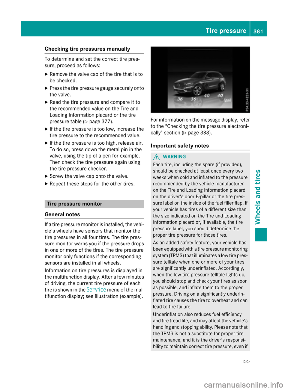
tire is shown in the Service
menu of the mul-
tifunction display; see illustration (example).
For information on the message display, refer
to the "Checking the tire pressure electroni-
cally" section (
Ypage 383).
Important safety notes
GWARNING
Each tire, including the spare (if provided),
should be checked at least once every two
weeks when cold and inflated to the pressure recommended by the vehicle manufacturer
on the Tire and Loading Information placard
on the driver's door B-pillar or the tire pres-
sure label on the inside of the fuel filler flap. If
your vehicle has tires of a different size than
the size indicated on the Tire and Loading
Information placard or, if available, the tire
pressure label, you should determine the
proper tire pressure for those tires.
As an added safety feature, your vehicle has
been equipped with a tire pressure monitoring
system (TPMS) that illuminates a low tire pres-
sure telltale when one or more of your tires
are significantly underinflated. Accordingly,
when the low tire pressure telltale lights up,
you should stop and check your tires as soon
as possible, and inflate them to the proper
pressure. Driving on a significantly underin-
flated tire causes the tire to overheat and can
lead to tire failure.
Underinflation also reduces fuel efficiency
and tire tread life, and may affect the vehicle's
handling and stopping ability. Please note thatthe TPMS is not a substitute for proper tire
maintenance, and it is the driver's responsi-
bility to maintain correct tire pressure, eve n if
Tire pressure381
Wheels and tires
Z
Page 395 of 418
DOT (Department of Transportation)
DOT-markedtires fulfill th erequirements of
th e U S Departmen tof Transportation .
Normal occupant weigh t
The number of occupant sfo rwhic hth evehi-
cle is designed multiplie dby 68 kilograms
(15 0lbs) .
Unifor mTire Qualit yGrading Standards
A uniform standard to grade th equalit yof
tires wit hregards to tread quality, tire traction
and temperature characteristics .The qualit y
gradin gassessmen tis made by th emanufac -
turer following specification sfrom th eU.S.
government. The ratings are molded into th e
sidewall of th etire.
Recommended tire pressure s
The recommended tire pressur eapplies to
th etires mounted at th efactory.
The Tir eand Loadin gInformation placard con-
tains th erecommended tire pressures fo r
cold tires on afull yloade dvehicl eand fo rth e
maximum permissibl evehicl espeed.
The tire pressur etable contain sth erecom-
mended pressures fo rcold tires fo rvarious
operating conditions, i.e. differin gload and
speed conditions.
Increased vehicle weigh tdu eto optiona l
equipment
The combine dweight of all standard and
optional equipmen tavailable fo rth evehicle,
regardless of whether it is a
ctually installed
on th evehicl eor not.
Ri m
This is th epart of th ewhee lon whic hth etire
is mounted.
GAW R(Gross Axle Weight Rating)
The GAW Ris th emaximum gross axl eweight
rating. The actual load on an axl emus tnever
exceed th egross axl eweight rating. The
gross axl eweight ratin gcan be found on th e
vehicl eidentification plat eon th eB-pillar on
th edriver's side . Speed rating
The speed ratin
gis part of th etire identifica-
tion .It specifies th espeed range fo rwhic hth e
tire is approved.
GV W(Gross Vehicle Weight )
The gross vehicl eweight includes th eweight
of th evehicl eincludin gfuel ,tools ,th espar e
wheel, accessories installed ,occupants, lug-
gage and th edrawbar noseweight ,if applica-
ble. The gross vehicl eweight mus tno texceed
th egross vehicl eweight ratin gGVWR as
specified on th evehicl eidentification plat eon
th eB-pillar on th edriver's side .
GVWR (Gross Vehicle Weight Rating)
The GVWR is th emaximum permissibl egross
weight of afull yloade dvehicl e(the weight of
th evehicl eincludin gall accessories, occu-
pants ,fuel, luggage and th edrawbar nose-
weight ,if applicable). The gross vehicl e
weight ratin gis specified on th
eve
hicl eiden -
tification plat eon th eB-pillar on th edriver's
side .
Maximum loaded vehicle weigh t
The maximum weight is th esum of :
Rthecur bweight of th evehicl e
Rtheweight of th eaccessories
Rth eload limi t
Rtheweight of th efactory installed optional
equipmen t
Kilopascal (kPa)
Metric uni tfo rtire pressure. 6. 9kP acorre-
spond sto 1psi .Another uni tfo rtire pressur e
is bar. 10 0kilopascal s(kPa) are th eequiva-
len tof 1bar.
Load index
In addition to th eload-bearin gindex ,th eload
index may also be imprinte don th esidewall of
th etire. This specifies th eload-bearin gcapa-
cit ymor eprecisely.
All about wheels and tires39 3
Wheels and tires
Z
Page 396 of 418
Curb weight
The weight of a vehicle with standard equip-
ment including the maximum capacity of fuel,
oil and coolant. It also includes the air-condi-
tioning system and optional equipment if
these are installed in the vehicle, but does not
include passengers or luggage.
Maximum load rating
The maximum tire load is the maximum per-
missible weight in kilograms or lbs for which a
tire is approved.
Maximum permissible tire pressure
Maximum permissible tire pressure for one
tire.
Maximum load on one tire
Maximum load on one tire. This is calculated
by dividing the maximum axle load of one axle
by two.
PSI (pounds per square inch)
A standard unit of measure for tire pressure.
Aspect ratio
Relationship between tire height and tire
width in percent.
Tire pressure
This is pressure inside the tire applying an
outward force to each square inch of the tire's
surface. The tire pressure is specified in
pounds per square inch (psi), in kilopascal
(kPa) or in bar. The tire pressure should only
be corrected when the tires are cold.
Cold tire pressure
The tires are cold:
Rif the vehicle has been parked with the tires
out of direct sunlight for at least three
hours and
Rif the vehicle has not been driven further
than 1 mile (1.6 km) Tread
The part of the tire that comes into contact
with the road.
Bead
The tire bead ensures that the tire sit
s
securely on t
he wheel. There are several steel
wires in the bead to prevent the tire from
coming loose from the wheel rim.
Sidewall
The part of the tire between the tread and the bead.
Weight of optional extras
The combined weight of those optional extras
that weigh more than the replaced standard
parts and more than 5 lbs (2.3 kg). These
optional extras, such as high-performance
brakes, level control, a roof rack or a high-
performance battery, are not included in the
curb weight and the weight of the accesso-
ries.
TIN (Tire Identification Number)
This is a unique identifier which can be used
by a tire manufacturer to identify tires, for
example for a product recall, and thus identify
the purchasers. The TIN is made up of the
manufacturer's identity code, tire size, tire
type code and the manufacturing date.
Load bearing index
The load bearing index (also load index) is a
code that contains the maximum load bearing
capacity of a tire.
Traction
Traction is the result of friction between the
tires and the road surface.
Treadwear indicators
Narrow bars (tread wear bars) that are dis-
tributed over the tire tread. If the tire tread is
level with the bars, the wear limit of áin
(1.6 mm) has been reached.
394All about wheels and tires
Wheels and tires
Page 398 of 418
XShift the transmission to positionP.
XMake sure that the vehicle level is set to
"Normal" on vehicles with AIR BODY CON-
TROL (
Ypage 196).
XSwitch off the engine.
XVehicles without KEYLESS-GO:remove
the SmartKey from the ignition lock.
XVehicles with KEYLESS-GO start-func-
tion or KEYLESS-GO: open the driver's
door.
The on-board electronics now have status
0 . This is the same as the SmartKey having
been removed.
XVehicles with KEYLESS-GO start-func-
tion or KEYLESS-GO: remove the Start/
Stop button from the ignition lock
(
Ypage 153).
XMake sure that the engine cannot be star-
ted via your smartphone (
Ypage 156).
XIf included in the vehicle equipment,
remove the tire-change tool kit from the
vehicle.
XSafeguard the vehicle against rolling away.
Securing the vehicle to prevent it from
rolling away
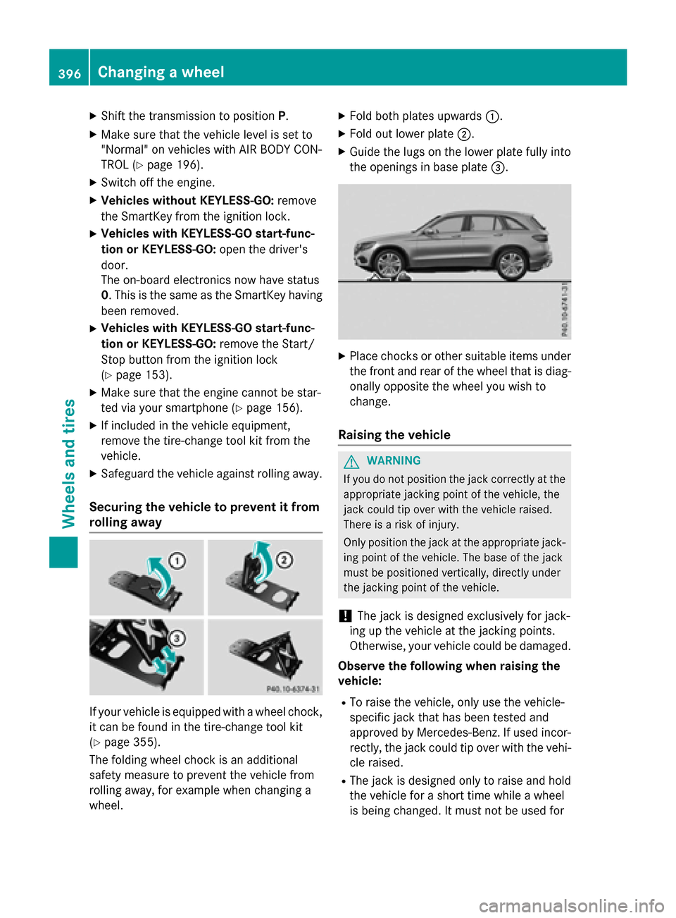
If your vehicle is equipped with a wheel chock,
it can be found in the tire-change tool kit
(
Ypage 355).
The folding wheel chock is an additional
safety measure to prevent the vehicle from
rolling away, for example when changing a
wheel.
XFold both plates upwards :.
XFold out lower plate;.
XGuide the lugs on the lower plate fully into
the openings in base plate =.
XPlace chocks or other suitable items under
the front and rear of the wheel that is diag-
onally opposite the wheel you wish to
change.
Raising the vehicle
GWARNING
If you do not position the jack correctly at the
appropriate jacking point of the vehicle, the
jack could tip over with the vehicle raised.
There is a risk of injury.
Only position the jack at the appropriate jack-
ing point of the vehicle. The base of the jack
must be positioned vertically, directly under
the jacking point of the vehicle.
!The jack is designed exclusively for jack-
ing up the vehicle at the jacking points.
Otherwise, your vehicle could be damaged.
Observe the following when raising the
vehicle:
RTo raise the vehicle, only use the vehicle-
specific jack that has been tested and
approved by Mercedes-Benz. If used incor-
rectly, the jack could tip over with the vehi- cle raised.
RThe jack is designed only to raise and hold
the vehicle for a short time while a wheel
is being changed. It must not be used for
396Changing a wheel
Wheels and tires
Page 399 of 418
performing maintenance work under the
vehicle.
RAvoid changing the wheel on uphill and
downhill slopes.
RBefore raising the vehicle, secure it from
rolling away by applying the parking brake
and inserting wheel chocks. Do not disen-
gage the parking brake while the vehicle is
raised.
RThe jack must be placed on a firm, flat and
non-slip surface. On a loose surface, a
large, flat, load-bearing underlay must be
used. On a slippery surface, a non-slip
underlay must be used, e.g. rubber mats.
RDo not use wooden blocks or similar
objects as a jack underlay. Otherwise, the
jack will not be able to achieve its load-
bearing capacity due to the restricted
height.
RMake sure that the distance between the
underside of the tires and the ground does
not exceed 1.2 in (3 cm).
RNever place your hands and feet under the
raised vehicle.
RDo not lie under the vehicle.
RDo not start the engine when the vehicle is
raised.
RNever open or close a door or the tailgate
when the vehicle is raised.
RMake sure that no persons are present in
the vehicle when the vehicle is raised.
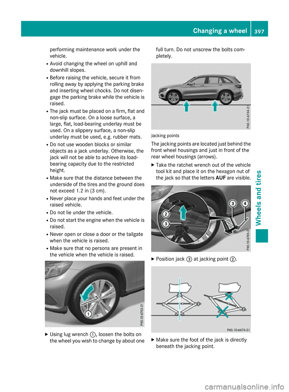
XUsing lug wrench :, loosen the bolts on
the wheel you wish to change by about one full turn. Do not unscrew the bolts com-
pletely.
Jacking points
The jacking points are located just behind the
front wheel housings and just in front of the
rear wheel housings (arrows).
XTake the ratchet wrench out of the vehicle
tool kit and place it on the hexagon nut of
the jack so that the letters AUFare visible.
XPosition jack =at jacking point ;.
XMake sure the foot of the jack is directly
beneath the jacking point.
Changing a wheel397
Wheels and tires
Z
Page 400 of 418
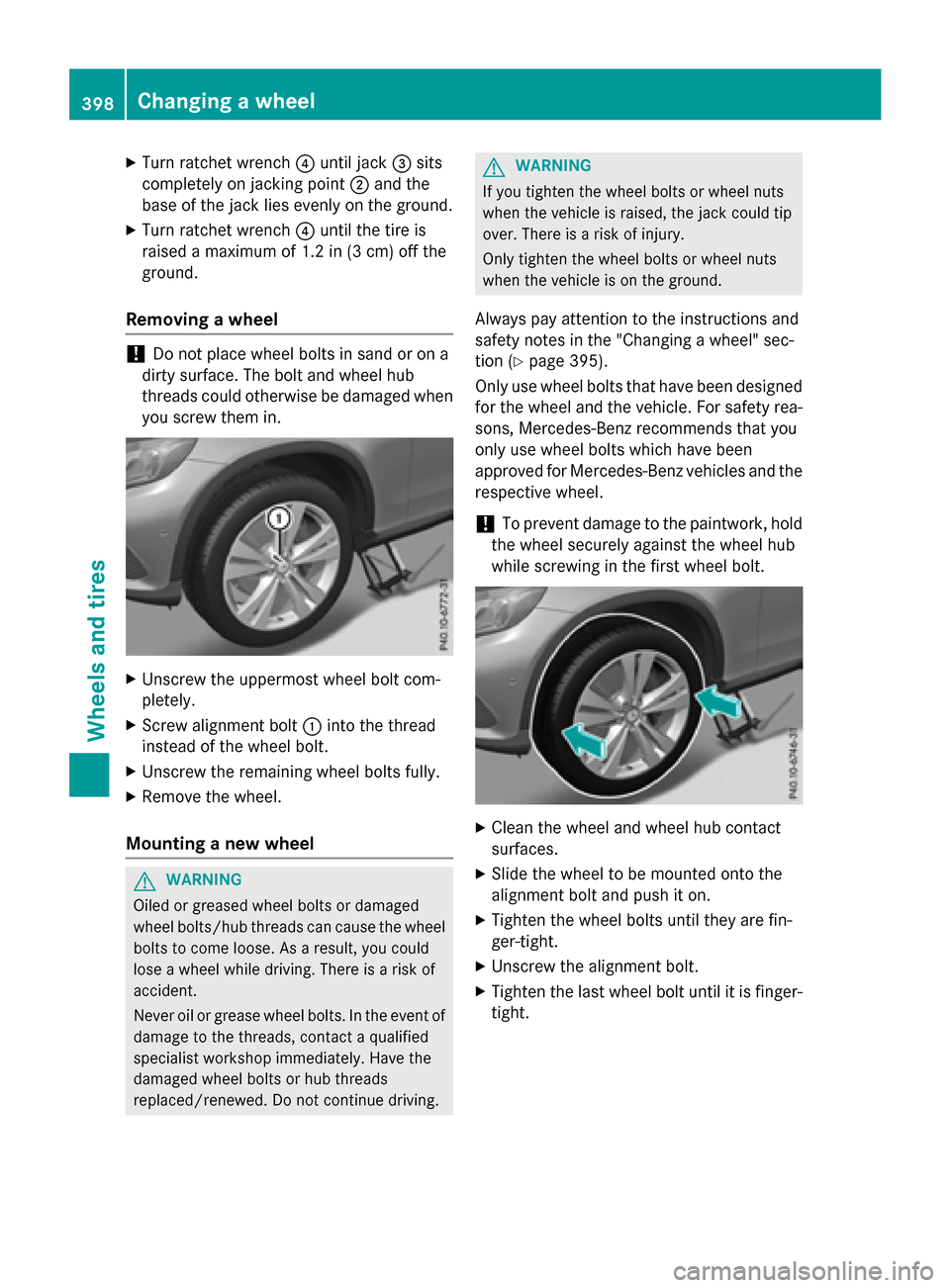
XTurn ratchet wrench?until jack =sits
completely on jacking point ;and the
base of the jack lies evenly on the ground.
XTurn ratchet wrench ?until the tire is
raised a maximum of 1.2 in (3 cm) off the
ground.
Removing a wheel
!Do not place wheel bolts in sand or on a
dirty surface. The bolt and wheel hub
threads could otherwise be damaged when
you screw them in.
XUnscrew the uppermost wheel bolt com-
pletely.
XScrew alignment bolt :into the thread
instead of the wheel bolt.
XUnscrew the remaining wheel bolts fully.
XRemove the wheel.
Mounting a new wheel
GWARNING
Oiled or greased wheel bolts or damaged
wheel bolts/hub threads can cause the wheel bolts to come loose. As a result, you could
lose a wheel while driving. There is a risk of
accident.
Never oil or grease wheel bolts. In the event of
damage to the threads, contact a qualified
specialist workshop immediately. Have the
damaged wheel bolts or hub threads
replaced/renewed. Do not continue driving.
GWARNING
If you tighten the wheel bolts or wheel nuts
when the vehicle is raised, the jack could tip
over. There is a risk of injury.
Only tighten the wheel bolts or wheel nuts
when the vehicle is on the ground.
Always pay attention to the instructions and
safety notes in the "Changing a wheel" sec-
tion (
Ypage 395).
Only use wheel bolts that have been designed for the wheel and the vehicle. For safety rea-
sons, Mercedes-Benz recommends that you
only use wheel bolts which have been
approved for Mercedes-Benz vehicles and the
respective wheel.
!To prevent damage to the paintwork, hold
the wheel securely against the wheel hub
while screwing in the first wheel bolt.
XClean the wheel and wheel hub contact
surfaces.
XSlide the wheel to be mounted onto the
alignment bolt and push it on.
XTighten the wheel bolts until they are fin-
ger-tight.
XUnscrew the alignment bolt.
XTighten the last wheel bolt until it is finger-
tight.
398Changing a wheel
Wheels and tires