key MERCEDES-BENZ GLE-Class 2016 C292 Owner's Manual
[x] Cancel search | Manufacturer: MERCEDES-BENZ, Model Year: 2016, Model line: GLE-Class, Model: MERCEDES-BENZ GLE-Class 2016 C292Pages: 382, PDF Size: 8.83 MB
Page 302 of 382
with Canadian law, some U.S. garage door open-
ers also feature a "break".
Proceed as follows:
Rif you live in Canada
Rif you have difficulties programming the
garage door opener (regardless of where you
live) when using the programming steps
XPress and hold one of buttons;to? on the
integrated garage door opener.
After a short time, indicator lamp :lights up
yellow.
XRelease the button.
Indicator lamp :flashes yellow.
XPress button Bof garage door remote con-
trol Afor two seconds, then release it for two
seconds.
XPress button Bagain for two seconds.
XRepeat this sequence on button Bof remote
control Auntil indicator lamp :lights up
green.
When indicator lamp :lights up green: pro-
gramming is finished.
When indicator lamp :flashes green: pro-
gramming was successful. The next step is to
synchronize the rolling code.
XRelease button Bof remote control Aof the
garage door drive.
If indicator lamp :lights up red: repeat the
programming process for the corresponding
button on the rear-view mirror. When doing
so, vary the distance between remote control
A and the rear-view mirror.
The required distance between remote con-
trol Aand the integrated garage door opener
depends on the garage door drive system.
Several attempts might be necessary. You
should test every position for at least
25 seconds before trying another position.
Problems when programming
If you are experiencing problems programing
th e integrated garage door opener on the rear-
view mirror, take note of the following instruc-
tions:
RCheck the transmitter frequency used by
garage door drive remote control Aand
whether it is supported. The transmitter fre-
quency can usually be found on the back of
the garage door drive remote control.
The integrated garage door opener is com-
patible with devices that have units which operate in the frequency range of 280 to
433 MHz.
RReplace the batteries in garage door remote
control
A. This increases the likelihood that
garage door remote control Awill transmit a
strong and precise signal to the integrated
garage door opener.
RWhen programming, hold remote control A
at varying distances and angles from the but-
ton which you are programming. Try various
angles at a distance between 2and 12 inches
(5to 30 cm) or at the same angle but at varying
distances.
RIf another remote control is available for the
same garage door drive, repeat the same pro-
gramming steps with this remote control.
Before performing these steps, make sure
that new batteries have been installed in
garage door drive remote control A.
RNote that some remote controls only transmit
for a limited amount of time (the indicator
lamp on the remote control goes out). Press
buttonBon remote control Aagain before
transmission ends.
RAlign the antenna cable of the garage door
open er unit. This can improve signal recep-
tion/transmission.
Opening/closing the garage door
After it has been programmed, the integrated
garage door opener performs the function of the
garage door system remote control. Please also
read the operating instructions for the garage
door system.
XTurn the SmartKey to position 2in the ignition
lock (Ypage 134).
XPress button ;,=or? which you have
programmed to operate the garage door.
Garage door system with a fixed code: indi-
cator lamp :lights up green.
Garage door system with a rolling code: indi-
cator lamp :flashes green.
The transmitter will transmit a signal as long
as the button is pressed. The transmission is
halted after a maximum of ten seconds and
indicator lamp :lights up yellow.
XPress button ;,=or? again if necessary.
300Features
Stowage and features
Page 303 of 382

Clearing the memory
Make sure that you clear the memory of the
integrated garage door opener before selling the
vehicle.
XTurn the SmartKey to position2in the ignition
lock (Ypage 134).
XPress and hold buttons ;and ?.
The indicator lamp initially lights up yellow
and then green.
XRelease buttons ;and ?.
The memory of the integrated garage door
opener in the rear-view mirror is cleared.
Floormats
GWARNING
Objects in the driver's footwell can restrict the pedal travel or obstruct a depressed pedal.
The operating and road safety of the vehicle is
jeopardized. There is a risk of an accident.
Make sure that all objects in the vehicle are
stowed correctly, and that they cannot enter
the driver's footwell. Install the floormats
securely and as specified in order to ensure
sufficient clearance for the pedals. Do not use
loose floormats and do not place floormats on
top of one another.
XDriver's seat/front-passenger seat: slide
the respective seat back.
XRear seats: slide the corresponding front
seat forwards.
XTo install: place the floormat in the footwell.
XPress studs :onto retainers ;.
XTo remove:pull the floormat from retain-
ers ;.
XRemove the floormat.
Features301
Stowage and features
Z
Page 307 of 382

XTurn cap:counter-clockwise and remove it.
XAdd engine oil.
If the oil level is at or below the MIN mark on
the oil dipstick, add 1.1 US qt (1.0 l)of engine
oil.
XReplace cap :on the filler neck and tighten
clockwise.
Ensure that the cap locks into place securely.
XCheck the oil level again with the oil dipstick
(Ypage 303).
Further information on engine oil (
Ypage 370).
Additional service products
Checking coolant level
GWARNING
Certain components in the engine compart-
ment, such as the engine, radiator and parts
of the exhaust system, can become very hot.
Working in the engine compartment poses a
risk of injury.
Where possible, let the engine cool down and touch only the components described in the
following.
GWARNING
The cooling system is pressurized, particularly
when the motor is warm. If you open the cap,
you could be scalded if hot coolant sprays out.
There is a risk of injury.
Let the engine cool down before you open the
cap. Wear gloves and eye protection. Slowly
open the cap to relieve pressure.
XPark the vehicle on a level surface. Only check the coolant level when the vehicle
is on a level surface and the engine has cooled
down.
XTurn the SmartKey to position 2in the ignition
lock (Ypage 134).
On vehicles with KEYLESS-GO, press the
Start/Stop button twice (
Ypage 136).
XCheck the coolant temperature gauge in the
multifunction display.
The coolant temperature must be below
158 ‡ (70 †).
XTurn the SmartKey to position 0in the ignition
lock (Ypage 134).
XSlowly turn cap :half a turn counter-clock-
wise and allow excess pressure to escape.
XTurn cap :further counter-clockwise and
remove it.
If the coolant is at the level of marker bar =
in the filler neck when cold, there is enough
coolant in coolant expansion tank ;.
If the coolant level is approximately 0.6 in
(1.5 cm) above marker bar =in the filler neck
when warm, there is enough coolant in expan-
sion tank ;.
XIf necessary, add coolant that has been tested
and approved by Mercedes-Benz.
XReplace cap :and turn it clockwise as far as
it will go.
For further information on coolant, see
(
Ypage 372).
Adding washer fluid to the windshield
washer system
GWARNING
Certain components in the engine compart-
ment, such as the engine, radiator and parts
of the exhaust system, can become very hot.
Working in the engine compartment poses a
risk of injury.
Where possible, let the engine cool down and touch only the components described in the
following.
GWARNING
Windshield washer concentrate could ignite if it comes into contact with hot engine compo-
nents or the exhaust system. There is a risk of
fire and injury.
Engine compartment305
Maintenance and care
Z
Page 310 of 382
the width of the tire wall on the rear wheel,
see "Technical data")
Ryou enter the automatic car wash straight
and in the center of the guide rails in order
to avoid damaging the tires or wheel rims.
Fold in the exterior mirrors before the vehicle
is washed. The exterior mirrors could other-
wise be damaged.
!If DISTRONIC PLUS or the HOLD function is
activated, the vehicle brakes automatically in
certain situations.
To prevent damage to the vehicle, deactivate
DISTRONIC PLUS and the HOLD function in
the following or other similar situations:
Rwhen towing the vehicle
Rin the car wash
!Never clean your vehicle in a Touchless
Automatic Car Wash as these use special
cleaning agents. These cleaning agents can
damage the paintwork or plastic parts.
!Make sure that:
Rthe side windows and the sliding sunroof
are fully closed.
Rthe ventilation/heating is switched off (the
OFF button has been pressed).
Rthe windshield wiper switch is in position 0.
Otherwise, the vehicle might be damaged.
!In car washes with a towing mechanism,
make sure that the automatic transmission is
in transmission position N, otherwise the
vehi
cle could be damaged.
RVehicles with a SmartKey:
Do not remove the SmartKey from the igni-
tion lock. Do not open the driver's door or
front-passenger door when the engine is
switched off. Otherwise, the automatic
transmission selects park position Pauto-
matically and locks the wheels. You can
prevent this by shifting the automatic trans-
mission to Nbeforehand.
RVehicles with KEYLESS-GO:
Do not open the driver's door or front-
passenger door when the engine is
switched off. Otherwise, the automatic
transmission selects park position Pauto-
matically and locks the wheels.
Observe the following to make sure that the
automatic transmission stays in position N:
XMake sure the vehicle is stationary and the
ignition is switched off.
XTurn the SmartKey to position2in the ignition
lock (Ypage 134).
Use the SmartKey instead of the Start/Stop
button on vehicles with KEYLESS-GO.
XDepress and hold the brake pedal.
XShift the automatic transmission to position
N.
XRelease the brake pedal.
XRelease the electric parking brake.
XSwitch off the ignition and leave the SmartKey
in the ignition lock.
You can wash the vehicle in an auto
matic car
wash from the very start.
If the vehicle is very dirty, pre-wash it before
cleaning it in an automatic car wash.
After using an automatic car wash, wipe off wax
from the windshield and the wiper blades. This
will prevent smears and reduce wiping noises
caused by residue on the windshield.
Washing by hand
In some countries, washing by hand is only
allowed at specially equipped washing bays.
Observe the legal requirements in all countries
concerned.
XDo not use hot water and do not wash the
vehicle in direct sunlight.
XUse a soft sponge to clean.
XUse a mild cleaning agent, such as a car
shampoo approved by Mercedes-Benz.
XThoroughly hose down the vehicle with a gen-
tle jet of water.
XDo not point the water jet directly towards the
air inlets.
XUse plenty of water and rinse out the sponge
frequently.
XRinse the vehicle with clean water and dry
thoroughly with a chamois.
XDo not let the cleaning agent dry on the paint-
work.
When using the vehicle in winter, remove all
traces of road salt deposits carefully and as
soon as possible.
308Care
Maintenance and care
Page 313 of 382
Cleaning the exterior lighting
!Only use cleaning agents or cleaning cloths
which are suitable for plastic light lenses.
Unsuitable cleaning agents or cleaning cloths
could scratch or damage the plastic light len- ses.
XClean the plastic lenses of the exterior light-
ing using a wet sponge and a mild cleaning
agent, e. g. Mercedes-Benz car shampoo or
cleaning cloths.
Cleaning the mirror turn signals
!Only use cleaning agents or cleaning cloths
that are suitable for plastic lenses. Unsuitable
cleaning agents or cleaning cloths could
scratch or damage the plastic lenses of the
mirror turn signals.
XClean the plastic lenses of the mirror turn sig-
nals in the exterior mirror housing using a wet
sponge and mild cleaning agent, e.g.
Mercedes-Benz car shampoo or cleaning
cloths.
Cleaning the side running board
!Do not clean the aluminum inserts of the
side running board with alkaline or acidic
cleaners, such as wheel cleaner. Do not use
acidic wheel cleaners to remove brake dust.
The aluminum inserts could otherwise be
damaged.
Cleaning the sensors
!If you clean the sensors with a power
washer, make sure that you keep a distance
of at least 11.8 in (30 cm) between the vehicle
and the power washer nozzle. Information
about the correct distance is available from
the equipment manufacturer.
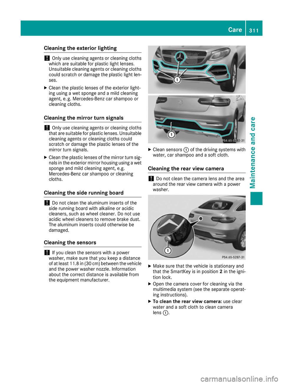
XClean sensors :of the driving systems with
water, car shampoo and a soft cloth.
Cleaning the rear view camera
!Do not clean the camera lens and the area
around the rear view camera with a power
washer.
XMake sure that the vehicle is stationary and
that the SmartKey is in position 2in the igni-
tion lock.
XOpen the camera cover for cleaning via the
multimedia system (see the separate operat-
ing instructions).
XTo clean the rear view camera: use clear
water and a soft cloth to clean camera
lens :.
Care311
Maintenance and care
Z
Page 314 of 382
Cleaning the 360° camera
!Do not clean the camera lens and the area
around the 360° camera with a power
washer.360
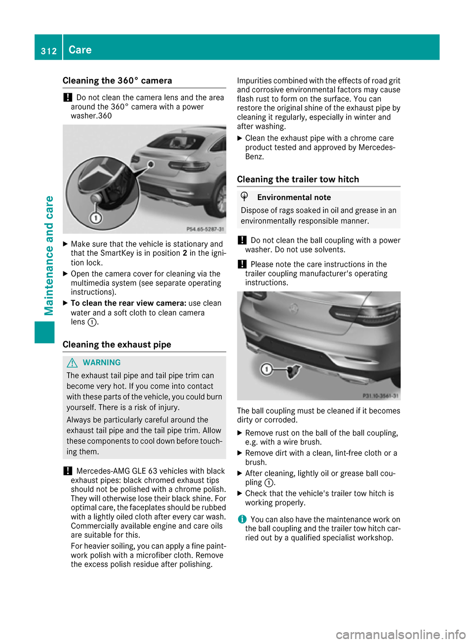
XMake sure that the vehicle is stationary and
that the SmartKey is in position 2in the igni-
tion lock.
XOpen the camera cover for cleaning via the
multimedia system (see separate operating
instructions).
XTo clean the rear view camera: use clean
water and a soft cloth to clean camera
lens :.
Cleaning the exhaust pipe
GWARNING
The exhaust tail pipe and tail pipe trim can
become very hot. If you come into contact
with these parts of the vehicle, you could burn
yourself. There is a risk of injury.
Always be particularly careful around the
exhaust tail pipe and the tail pipe trim. Allow
these components to cool down before touch-
ing them.
!Mercedes-AMG GLE 63 vehicles with black
exhaust pipes: black chromed exhaust tips
should not be polished with a chrome polish. They will otherwise lose their black shine. For
optimal care, the faceplates should be rubbed with a lightly oiled cloth after every car wash.
Commercially available engine and care oils
are suitable for this.
For heavier soiling, you can apply a fine paint-
work polish with a microfiber cloth. Remove
the excess polish residue after polishing. Impurities combined with the effects of road grit
and corrosive environmental factors may cause
flash rust to form on the surface. You can
restore the original shine of the exhaust pipe by
cleaning it regularly, especially in winter and
after washing.
XClean the exhaust pipe with a chrome care
product tested and approved by Mercedes-
Benz.
Cleaning the trailer tow hitch
HEnvironmental note
Dispose of rags soaked in oil and grease in an
environmentally responsible manner.
!Do not clean the ball coupling with a power
washer. Do not use solvents.
!Please note the care instructions in the
trailer coupling manufacturer's operating
instructions.
The ball coupling must be cleaned if it becomes
dirty or corroded.
XRemove rust on the ball of the ball coupling,
e.g. with a wire brush.
XRemove dirt with a clean, lint-free cloth or a
brush.
XAfter cleaning, lightly oil or grease ball cou-
pling :.
XCheck that the vehicle's trailer tow hitch is
working properly.
iYou can also have the maintenance work on
the ball coupling and the trailer tow hitch car-
ried out by a qualified specialist workshop.
312Care
Maintenance and care
Page 318 of 382
XVehicles with the AIRMATIC package:
make sure that the normal vehicle level is
selected (
Ypage 183).
XSwitch off the engine.
XVehicles without KEYLESS-GO:remove the
SmartKey from the ignition lock.
XVehicles with KEYLESS-GO: open the driv-
er's door.
The on-board electronics now have status 0.
This is the same as the SmartKey having been
removed.
XVehicles with KEYLESS-GO: remove the
Start/Stop button from the ignition lock
(
Ypage 134).
XMake sure that the engine cannot be started
via your smartphone (Ypage 136).
XMake sure that the passengers are not endan-
gered as they do so. Make sure that no one is
near the danger area while a wheel is being
changed. Anyone who is not directly assisting
in the wheel change should, for example,
stand behind the barrier.
XGet out of the vehicle. Pay attention to traffic
conditions when doing so.
XClose the driver's door.
iOnly operate the tire inflation compressor
using a 12 V socket, even if the ignition is
turned off (
Ypage 289).
An emergency cut-out ensures that the on-
board voltage does not drop too low. If the on-
board voltage is too low, the power to the
sockets is automatically cut. This ensures
that there is sufficient power to start the
engine.
MOExtended tires (tires with run-flat
properties)
General notes
With MOExtended tires (tires with run flat char-
acteristics), you can continue to drive your vehi-
cle even if there is a total loss of pressure in one
or more tires. The affected tire must not show
any clearly visible damage.
You can recognize MOExtended tires by the
MOExtended marking which appears on the
sidewall of the tire. You will find this marking
next to the tire size designation, the load-bear-
ing capacity and the speed index (
Ypage 346). MOExtended tires may only be used in conjunc-
tion with an active tire pressure loss warning
system or with an active tire pressure monitor.
If a pressure loss warning message appears
in the multifunction display:
Robserve the instructions in the display mes-
sages (Ypage 259).
Rcheck the tire for damage.
Rif driving on, observe the following notes.
The driving distance possible in run-flat mode is
approximately 50 miles (80 km) when the vehi-
cle is partially laden and approximately 18 miles
(30 km) when the vehicle is fully laden.
In addition to the vehicle load, the driving dis-
tance possible depends upon:
Rvehicle speed
Rroad condition
Routside temperature
The driving distance possible in run-flat mode
may be reduced by extreme driving conditions
or maneuvers, or it can be increased through a
moderate style of driving.
The driving dista
nce possible in run-flat mode is
counted from the moment the tire pressure loss
warning appears in the multifunction display.
You must not exceed a maximum speed of
50 mph (80 km/h).
When replacing one or all tires, please observe
the following specifications for your vehicle's
tires:
Rsize
Rtype and
Rthe "MOExtended" mark
Vehicles equipped with MOExtended tires are
not equipped with a TIREFIT kit at the factory. It
is therefore recommended that you additionally
equip your vehicle with a TIREFIT kit if you mount tires that do not feature run-flat properties, e.g.
winter tires. A TIREFIT kit may be obtained from
a qualified specialist workshop.
Important safety notes
GWARNING
When driving in emergency mode, the driving
characteristics deteriorate, e.g. when corner-
ing, accelerating quickly and when braking.
There is a risk of an accident.
316Flat tire
Breakdown assitance
Page 320 of 382
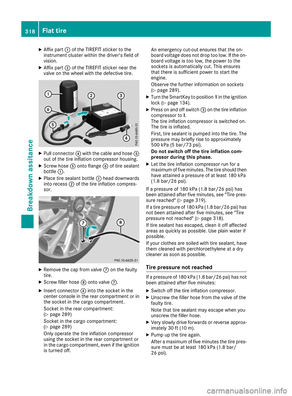
XAffix part:of the TIREFIT sticker to the
instrument cluster within the driver's field of
vision.
XAffix part ;of the TIREFIT sticker near the
valve on the wheel with the defective tire.
XPull connector ?with the cable and hose A
out of the tire inflation compressor housing.
XScrew hose Aonto flange Bof tire sealant
bottle :.
XPlace tire sealant bottle :head downwards
into recess ;of the tire inflation compres-
sor.
XRemove the cap from valve Con the faulty
tire.
XScrew filler hose Donto valve C.
XInsert connector ?into the socket in the
center console in the rear compartment or in
the socket in the cargo compartment.
Socket in the rear compartment:
(
Ypage 289)
Socket in the cargo compartment:
(
Ypage 289)
Only operate the tire inflation compressor
using the socket in the rear compartment or
in the cargo compartment, even if the ignition
is turned off. An emergency cut-out ensures that the on-
board voltage does not drop too low. If the on-
board voltage is too low, the power to the
sockets is automatically cut. This ensures
that there is sufficient power to start the
engine.
Observe the further information on sockets
(
Ypage 289).
XTurn the SmartKey to position
1in the ignition
lock (Ypage 134).
XPress on and off switch =on the tire inflation
compressor to I.
The tire inflation compressor is switched on.
The tire is inflated.
First, tire sealant is pumped into the tire. The
pressure may briefly rise to approximately
500 kPa (5 bar/73 psi).
Do not switch off the tire inflation com-
pressor during this phase.
XLet the tire inflation compressor run for a
maximum of five minutes. The tire should then
have attained a pressure of at lea
st 180 kPa
(1.8 bar/26 psi).
If a pressure of 180 kPa (1.8 bar/26 psi) has
been attained after five minutes, see "Tire pres-
sure reached" (
Ypage 319).
If a tire pressure of 180 kPa (1.8 ba r/26 psi) has
not been attained after five minutes, see "Tire
pressure not reached" (
Ypage 318).
If tire sealant has escaped, clean it off affected
areas as quickly as possible. Use plain water if
possible.
If your clothes are soiled with tire sealant, have
them cleaned with perchloroethylene at a dry
cleaner as soon as possible.
Tire pressure not reached
If a pressure of 180 kPa (1.8 bar/26 psi) has not
been attained after five minutes:
XSwitch off the tire inflation compressor.
XUnscrew the filler hose from the valve of the
faulty tire.
Note that tire sealant may escape when you
unscrew the filler hose.
XVery slowly drive forwards or reverse approx-
imately 30 ft (10 m).
XPump up the tire again.
After a maximum of five minutes the tire pres- sure must be at least 180 kPa (1.8 bar/
26 psi).
318Flat tire
Breakdown assitance
Page 323 of 382
GWARNING
Battery acid is caustic. There is a risk of injury.
Avoid contact with skin, eyes or clothing. Do
not inhale any battery gases. Do not lean over
the battery. Keep children away from batter-
ies. Wash away battery acid immediately with
plenty of clean water and seek medical atten-
tion.
HEnvironmental note
Batteries contain dangerous
substances. It is against the
law to dispose of them with
the household rubbish. They
must be collected separately and recycled to protect the
environment.
Dispose of batteries in an
environmentally friendly
manner. Take discharged
batteries to a qualified spe-
cialist workshop or a special
collection point for used bat-
teries.
!Have the battery checked regularly at a
qualified specialist workshop.
Observe the service intervals in the Mainte-
nance Booklet or contact a qualified specialist
workshop for more information.
!Always have work on batteries carried out at
a qualified specialist workshop. Should it, in
exceptional circumstances, be absolutely
necessary to disconnect the 12-volt battery
yourself, observe the following:
Rsecure the vehicle to prevent it from rolling
away.
Rswitch off the ignition.
Ralways disconnect the negative terminal
clamp first, followed by the positive termi-
nal clamp.
After the battery has been disconnected, the
transmission is locked in position P.
After the work has been done, install the bat-
tery and replace the cover of the positive ter-
minal clamp firmly.
Comply with safety precautions and take pro-
tective measures when handling batteries.
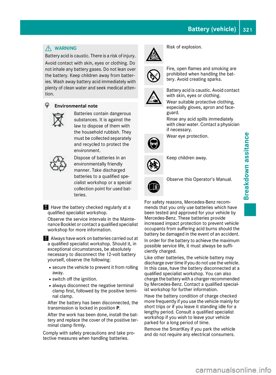
Risk of explosion.
Fire, open flames and smoking are
prohibited when handling the bat-
tery. Avoid creating sparks.
Battery acid is caustic. Avoid contact
with skin, eyes or clothing.
Wear suitable protective clothing,
especially gloves, apron and face-
guard.
Rinse any acid spills immediately
with clear water. Contact a physician
if necessary.
Wear eye protection.
Keep children away.
Observe this Operator's Manual.
For safety reasons, Mercedes-Benz recom-
mends that you only use batteries which have
been tested and approved for your vehicle by
Mercedes-Benz. These batteries provide
increased impact protection to prevent vehicle
occupants from suffering acid burns should the
battery be damaged in the event of an accident.
In order for the battery to achieve the maximum
possible service life, it must always be suffi-
ciently charged.
Like other batteries, the vehicle battery may
discharge over time if you do not use the vehicle.
In this case, have the battery disconnected at a
qualified specialist workshop. You can also
charge the battery with a charger recommended
by Mercedes-Benz. Contact a qualified special-
ist workshop for further information.
Have the battery condition of charge checked
more frequently if you use the vehicle mainly for
short trips or if you leave it standing idle for a
lengthy period. Consult a qualified specialist
workshop if you wish to leave your vehicle
parked for a long period of time.
Remove the SmartKey if you park the vehicle
and do not require any electrical consumers.
Battery (vehicle)321
Breakdown assitance
Z
Page 326 of 382
Do not start the vehicle using a rapid charging device. If your vehicle's battery is discharged, the
engine can be jump-started from another vehicle or from a second battery using jumper cables.
Observe the following points:
RThe battery is not accessible in all vehicles. If the other vehicle's battery is not accessible, jump-
start the vehicle using a second battery or a jump-starting device.
RVehicles with a gasoline engine: only jump-start the vehicle when the engine and exhaust
system are cold.
RDo not start the engine if the battery is frozen. Let the battery thaw first.
ROnly jump-start from batteries with a 12 V voltage rating.
ROnly use jumper cables which have a sufficient cross-section and insulated terminal clamps.
RIf the battery is fully discharged, leave the battery that is being used to jump-start connected for
a few minutes before attempting to start. This charges the battery slightly.
RMake sure that the two vehicles do not touch.
Make sure that:
RThe jumper cables are not damaged.
RBare parts of the terminal clamp do not come into contact with other metal parts while the jumper
cables are connected to the battery.
RThe jumper cables cannot come into contact with parts which can move when the engine is
running, such as the V-belt pulley or the fan.
XSecure the vehicle by applying the electric parking brake.
XShift the transmission to position P.
XMake sure that the ignition is switched off. All indicator lamps in the instrument cluster must be
off. When using the SmartKey, turn the SmartKey to position 0in the ignition lock and remove it
(
Ypage 134).
XSwitch off all electrical consumers, e.g. rear window defroster, lighting, etc.
XOpen the hood.
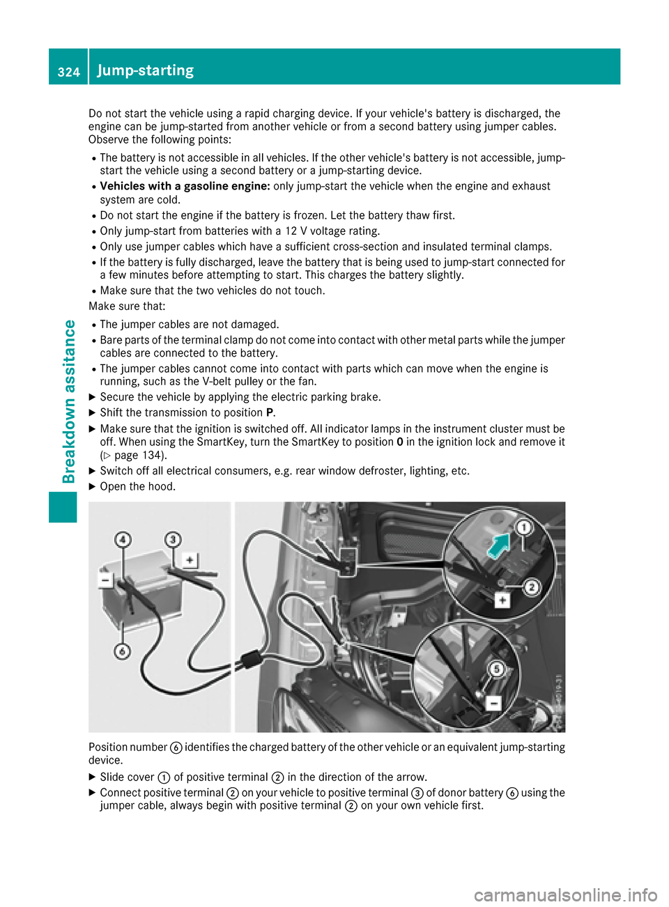
Position number Bidentifies the charged battery of the other vehicle or an equivalent jump-starting
device.
XSlide cover :of positive terminal ;in the direction of the arrow.
XConnect positive terminal ;on your vehicle to positive terminal =of donor battery Busing the
jumper cable, always begin with positive terminal ;on your own vehicle first.
324Jump-starting
Breakdown assitance