MERCEDES-BENZ GLE COUPE 2015 Owners Manual
Manufacturer: MERCEDES-BENZ, Model Year: 2015, Model line: GLE COUPE, Model: MERCEDES-BENZ GLE COUPE 2015Pages: 393, PDF Size: 12.71 MB
Page 231 of 393
Select the
Comfortdrive program using the
DYNAMIC SELECT controller (Y page 153).
The maximum permissible speed for vehicle/
trailer combinations depends on the type of
trailer. Before beginning the journey, check the
trailer's documents to see what the maximum
permitted speed is. Observe the legally prescri-
bed maximum speed in the relevant country.
For certain Mercedes-Benz vehicles, the maxi-
mum permissible rear axle load is increased
when towing a trailer. See the "Technical data"
section to find out whether this applies to your
vehicle (Y page 385). If you utilise any of the
added maximum rear axle load when towing a
trailer, the vehicle/trailer combination may not
exceed a maximum speed of 100 km/h for rea-
sons concerning the operating permit. This also
applies in countries in which the permissible
maximum speed for vehicle/trailer combina-
tions is above 100 km/h.
When towing a trailer, your vehicle's handling
characteristics will be different in comparison to when driving without a trailer and it will con-
sume more fuel.
Use the left-hand gearshift paddle to shift to a
lower gear on long and steep downhill gradients.
This also applies if you have activated cruise
control, SPEEDTRONIC or DISTRONIC PLUS.
This will use the braking effect of the engine, so
less braking will be required to maintain vehicle
speed. This relieves the load on the brake sys-
tem and prevents the brakes from overheating
and wearing too quickly. If you need additional
braking, depress the brake pedal repeatedly
rather than continuously.
Driving tips If the trailer swings from side to side:
X Do not accelerate.
X Do not countersteer.
X Brake if necessary.
R Maintain a greater distance to the vehicle in
front than when driving without a trailer.
R Avoid braking abruptly. If possible, brake gen-
tly at first to allow the trailer to run on. Then,
increase the braking force rapidly.
R The values given for gradient-climbing capa-
bilities from a standstill refer to sea level.
When driving in mountainous areas, note that
the power output of the engine, and conse- quently the vehicle's gradient-climbing capa-
bility, decrease with increasing altitude. Swinging out the ball coupling
G
WARNING
If the ball coupling is not engaged, the trailer
may come loose. There is a risk of an accident.
Make sure that the ball coupling is securely
engaged and locked in position.
! Do not attempt to speed the up the swing-
out procedure by applying additional pressure
with your foot. The system could otherwise be
mechanically damaged.
In order to tow a trailer with your vehicle, you
must swing out the ball coupling using the
switch in the driver's door or in the tailgate.
The trailer power socket is integrated into the
ball coupling and swivels out with it.
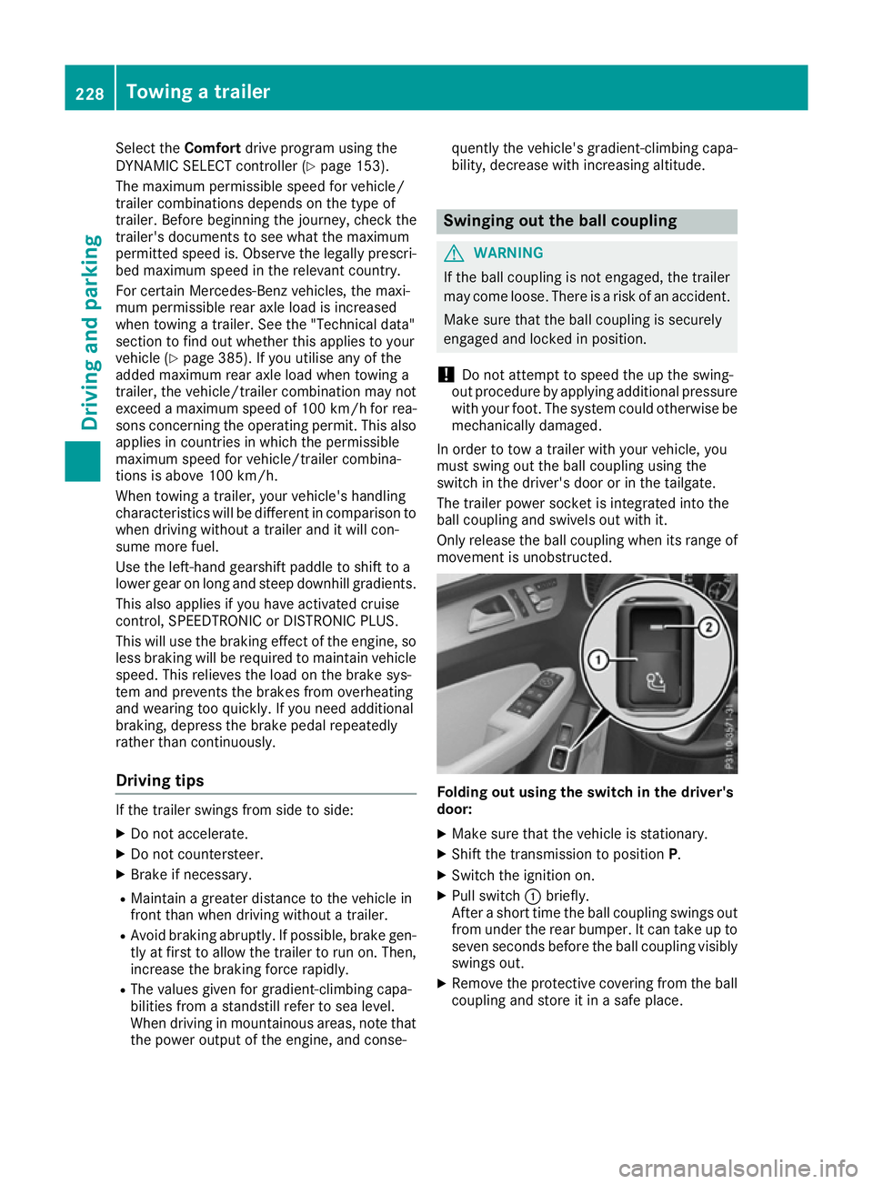
Only release the ball coupling when its range of movement is unobstructed. Folding out using the switch in the driver's
door:
X
Make sure that the vehicle is stationary.
X Shift the transmission to position P.
X Switch the ignition on.
X Pull switch :briefly.
After a short time the ball coupling swings out from under the rear bumper. It can take up to
seven seconds before the ball coupling visibly swings out.
X Remove the protective covering from the ball
coupling and store it in a safe place. 228
Towing a trailerDriving and parking
Page 232 of 393
Until the ball coupling securely engages and
locks in a vertical position:
R indicator lamp ;flashes
R the multifunction display shows the display
message Trailer coupling extend‐
Trailer coupling extend‐
ing... ing....
The ball coupling swivels back into the out-of-
use position when:
R
R you drive off before the Trailer Trailercoupling coupling
extending...
extending... display message has disap-
peared from the multifunction display
R the ball coupling encounters an obstacle in
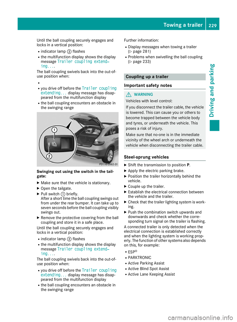
the swinging range Swinging out using the switch in the tail-
gate:
X Make sure that the vehicle is stationary.
X Open the tailgate.
X Pull switch :briefly.
After a short time the ball coupling swings out from under the rear bumper. It can take up to
seven seconds before the ball coupling visibly
swings out.
X Remove the protective covering from the ball
coupling and store it in a safe place.
Until the ball coupling securely engages and
locks in a vertical position:
R indicator lamp ;flashes
R the multifunction display shows the display
message Trailer coupling extend‐ Trailer coupling extend‐
ing...
ing....
The ball coupling swivels back into the out-of-
use position when:
R you drive off before the Trailer Trailercoupling
coupling
extending...
extending... display message has disap-
peared from the multifunction display
R the ball coupling encounters an obstacle in
the swinging range Further information:
R Display messages when towing a trailer
(Y page 281)
R Problems when swivelling the ball coupling
(Y page 233) Coupling up a trailer
Important safety notes G
WARNING
Vehicles with level control:
If you disconnect the trailer cable, the vehicle is lowered. This can cause you or others to
become trapped between the vehicle body
and tyres, or underneath the vehicle. This
poses a risk of injury.
Make sure that no-one is in the immediate
vicinity of the wheel arch or underneath the
vehicle when disconnecting the trailer cable.
Steel-sprung vehicles X
Shift the transmission to position P.
X Apply the electric parking brake.
X Position the trailer horizontally behind the
vehicle.
X Couple up the trailer.
X Establish the electrical connection between
the vehicle and the trailer.
X Check that the trailer lighting system is work-
ing.
X Push the combination switch upwards and
downwards and check whether the corre-
sponding turn signal on the trailer is flashing.
A connected trailer is only detected when the
electrical connection is established correctly
and when the lighting system is working prop-
erly. The function of other systems also depends on this, for example:
R ESP ®
R PARKTRONIC
R Active Parking Assist
R Active Blind Spot Assist
R Active Lane Keeping Assist Towing a trailer
229Driving and parking Z
Page 233 of 393
Vehicles with the AIRMATIC package
!
Before beginning the journey, make sure
that the trailer support wheel is completely
raised. Otherwise, the trailer or the vehicle
could be damaged by the lowered trailer sup- port wheel during the journey.
X Shift the transmission to position P.
X Apply the electric parking brake.
X Start the engine.
X Select the Comfortdrive program using the
DYNAMIC SELECT controller (Y page 195).
X Switch off the engine.
X Close the doors and tailgate.
X Position the trailer horizontally behind the
vehicle.
X Couple up the trailer.
X Establish the electrical connection between
the vehicle and the trailer.
X Check that the trailer lighting system is work-
ing.
X Push the combination switch upwards and
downwards and check whether the corre-
sponding turn signal on the trailer is flashing.
A connected trailer is only detected when the
electrical connection is established correctly
and when the lighting system is working prop-
erly. The function of other systems also depends on this, for example:
R ESP ®
R PARKTRONIC
R Active Parking Assist
R Active Blind Spot Assist
R Active Lane Keeping Assist
i Vehicles with the AIRMATIC package:
if
you couple up a trailer, the vehicle initially
remains at the selected level of the drive pro- gram set. Observe the following when cou-
pling up a trailer:
R If the normal level was not selected previ-
ously, the vehicle automatically adopts the
normal level starting from a speed of
30 km/h. Even at higher speeds, it does not drop below the normal level.
R Vehicle levels below the normal level are
not available.
R The raised level is available up to a speed of
30 km/h. R
This also applies when using accessories
that are plugged into the socket of the
trailer tow hitch (e.g. a bicycle rack).
R Before driving with a trailer, please observe
the information on the trailer support
wheel. Uncoupling a trailer
Important safety notes G
WARNING
If you uncouple a trailer with an engaged over- run brake, you could trap your hand between
the vehicle and the trailer drawbar. This poses a risk of injury.
Do not uncouple a trailer with an engaged
overrun brake. G
WARNING
Vehicles with level control:
If you disconnect the trailer cable, the vehicle is lowered. This can cause you or others to
become trapped between the vehicle body
and tyres, or underneath the vehicle. This
poses a risk of injury.
Make sure that no-one is in the immediate
vicinity of the wheel arch or underneath the
vehicle when disconnecting the trailer cable.
! Do not disconnect a trailer with an engaged
overrun brake. Otherwise, your vehicle could
be damaged by the rebounding of the overrun
brake.
! Remove the adapter cable before folding in
the ball coupling. You could otherwise dam-
age the rear bumper and the adapter cable.
Steel-sprung vehicles X
Shift the transmission to position P.
X Apply the electric parking brake.
X Secure the trailer against rolling away.
X Remove the trailer cable and decouple the
trailer. 230
Towing a trailerDriving an
d parking
Page 234 of 393
Vehicles with the AIRMATIC package
X
Shift the transmission to position P.
X Apply the electric parking brake.
X Start the engine.
X Close the doors and tailgate.
X Secure the trailer against rolling away.
X Remove the trailer cable and decouple the
trailer.
X Switch off the engine. Swinging the ball coupling in
! Do not attempt to speed the up the swing-
out procedure by applying additional pressure
with your foot. The system could otherwise be
mechanically damaged.
Swing the ball coupling back in using the switch
on the driver's door or tailgate, if you are not
using the trailer tow hitch.
Only release the ball coupling when its range of movement is unobstructed. Folding in using the switch in the driver's
door:
X Make sure that the vehicle is stationary and
the trailer cables are disconnected.
X Place the protective covering on the ball cou-
pling.
X Shift the transmission to position P.
X Switch the ignition on.
X Briefly pull button :.
After a short time the ball coupling swings in
under the rear bumper. It can take up to seven seconds before the ball coupling visibly
swings in. Until the ball coupling securely engages and
locks under the bumper:
R indicator lamp ;flashes
R the multifunction display shows the display
message Trailer coupling extend‐
Trailer coupling extend‐
ing... ing...
The ball coupling swivels back into the out-of-
use position when:
R you drive off before the Trailer
Trailercoupling
coupling
extending...
extending... display message has disap-
peared from the multifunction display
R the ball coupling encounters an obstacle in
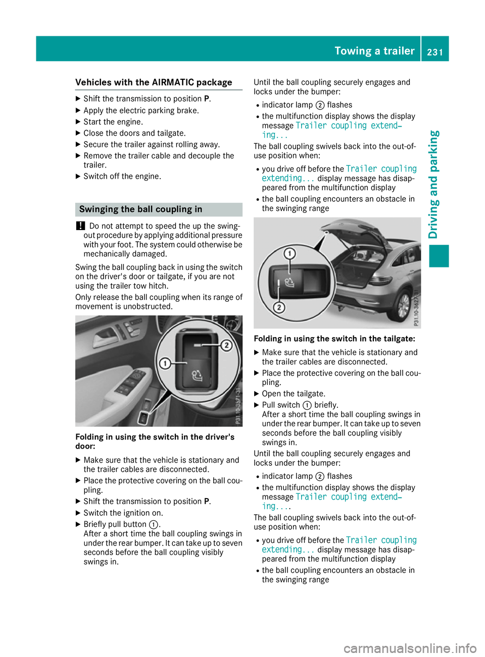
the swinging range Folding in using the switch in the tailgate:
X Make sure that the vehicle is stationary and
the trailer cables are disconnected.
X Place the protective covering on the ball cou-
pling.
X Open the tailgate.
X Pull switch :briefly.
After a short time the ball coupling swings in
under the rear bumper. It can take up to seven seconds before the ball coupling visibly
swings in.
Until the ball coupling securely engages and
locks under the bumper:
R indicator lamp ;flashes
R the multifunction display shows the display
message Trailer coupling extend‐ Trailer coupling extend‐
ing...
ing... .
The ball coupling swivels back into the out-of-
use position when:
R you drive off before the Trailer
Trailercoupling
coupling
extending...
extending... display message has disap-
peared from the multifunction display
R the ball coupling encounters an obstacle in
the swinging range Towing a trailer
231Driving and parking Z
Page 235 of 393
Further information:
R Display messages when towing a trailer
(Y page 281)
R Problems when swivelling the ball coupling
(Y page 233) Trailer power supply
! You can connect accessories with a power
rating of up to 180 W to the permanent power supply and with a power rating of up to 180 Wto the power supply that is switched on via the
ignition lock.
The trailer battery may not be charged from
the power supply.
When it leaves the factory, your vehicle's trailer
socket is equipped with a permanent power
supply and a power supply that is switched on
via the ignition lock.
The permanent power supply is supplied via
trailer socket pin 9.
The power supply that is switched on via the
ignition lock is supplied via trailer socket pin 10. The trailer's permanent power supply is
switched off in the event of low vehicle supply
voltage and after six hours at the latest.
You can find more information about fitting the
trailer electrics at a qualified specialist work-
shop.
X To switch the connected power supply on
or off: turn the key to position 2or 0respec-
tively (Y page 146). Failure check for LEDs
If LED lamps are fitted in the trailer, a malfunc-
tion message may appear in the multifunction
display even if there is no fault. The reason for
the error message may be that the current has
fallen below the minimum of 50 mA.
To ensure reliable indication of the failure, each LED chain in the trailer lighting must be guaran-
teed a minimum current of 50 mA. Trailer with 7-pin connector
General notes Trailer with 7-pin connector:
you can connect
to the 13-pin socket on the ball coupling using
an adapter or, if necessary, an adapter cable.
Both can be obtained at a qualified specialist
workshop.
Fitting the adapter !
Make sure that there is sufficient cable play
so that the cable cannot become detached
when cornering.
! Remove the adapter cable before folding in
the ball coupling. You could otherwise dam-
age the rear bumper and the adapter cable. X
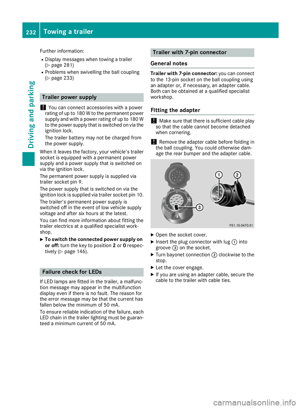
Open the socket cover.
X Insert the plug connector with lug :into
groove =on the socket.
X Turn bayonet connection ;clockwise to the
stop.
X Let the cover engage.
X If you are using an adapter cable, secure the
cable to the trailer with cable ties. 232
Towing a trailerDriving and parking
Page 236 of 393
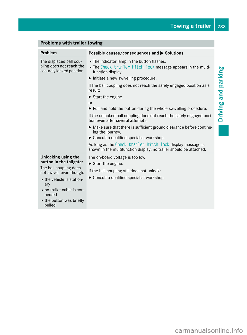
Problems with trailer towing
Problem
Possible causes/consequences and
M
MSolutions The displaced ball cou-
pling does not reach the
securely locked position. R
The indicator lamp in the button flashes.
R The Check trailer hitch lock Check trailer hitch lock message appears in the multi-
function display.
X Initiate a new swivelling procedure.
If the ball coupling does not reach the safely engaged position as a
result:
X Start the engine
or
X Pull and hold the button during the whole swivelling procedure.
If the unlocked ball coupling does not reach the safely engaged posi- tion even after several attempts:
X Make sure that there is sufficient ground clearance before continu-
ing the journey.
X Consult a qualified specialist workshop.
As long as the Check trailer hitch lock
Check trailer hitch lock display message is
shown in the multifunction display, no trailer should be attached. Unlocking using the
button in the tailgate:
The ball coupling does
not swivel, even though:
R
the vehicle is station-
ary
R no trailer cable is con-
nected
R the button was briefly
pulled The on-board voltage is too low.
X Start the engine.
If the ball coupling still does not unlock:
X Consult a qualified specialist workshop. Towing a trailer
233Driving and parking Z
Page 237 of 393
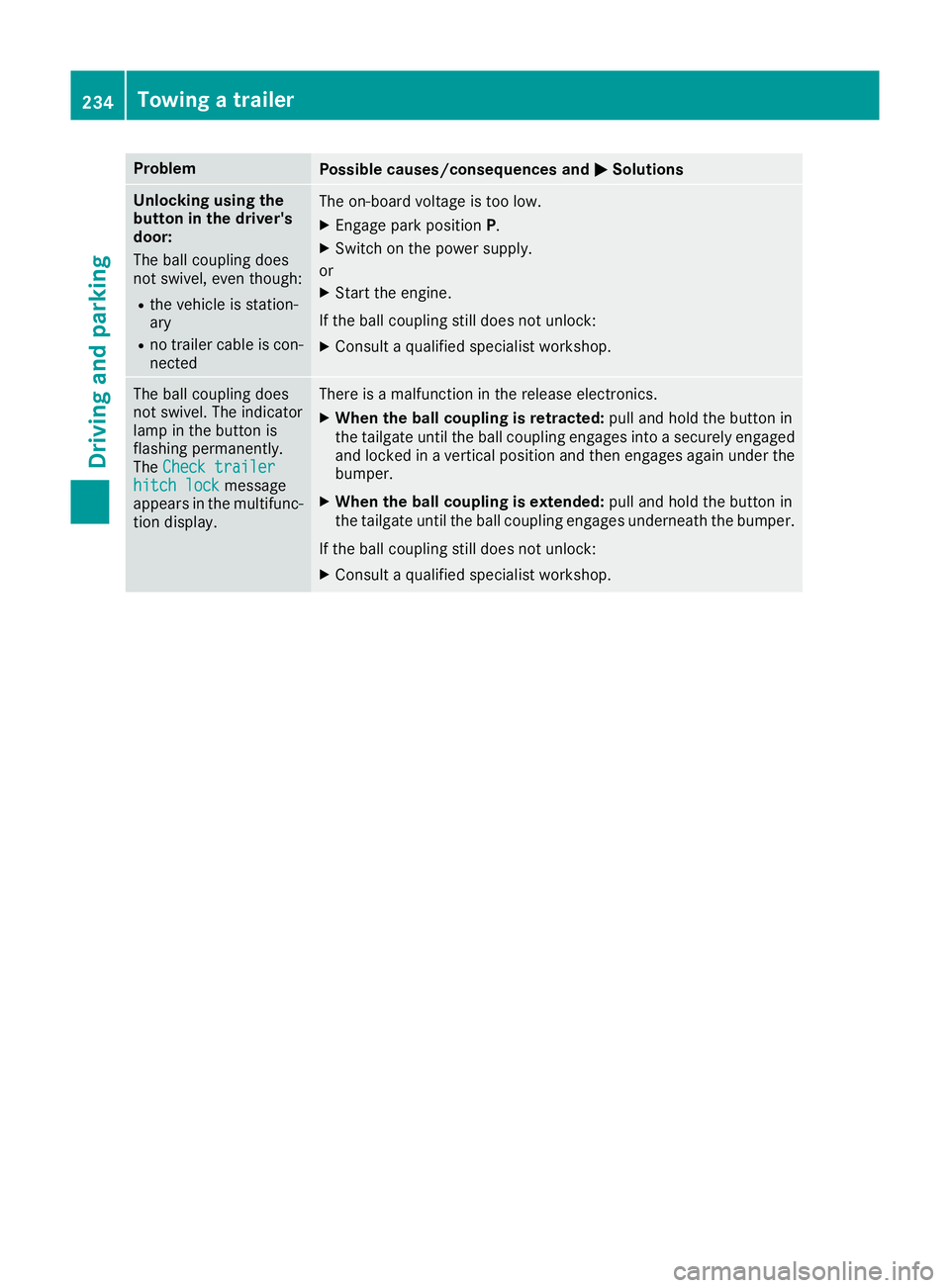
Problem
Possible causes/consequences and
M
MSolutions Unlocking using the
button in the driver's
door:
The ball coupling does
not swivel, even though:
R the vehicle is station-
ary
R no trailer cable is con-
nected The on-board voltage is too low.
X Engage park position P.
X Switch on the power supply.
or X Start the engine.
If the ball coupling still does not unlock: X Consult a qualified specialist workshop. The ball coupling does
not swivel. The indicator
lamp in the button is
flashing permanently.
The
Check trailer Check trailer
hitch lock
hitch lock message
appears in the multifunc- tion display. There is a malfunction in the release electronics.
X When the ball coupling is retracted: pull and hold the button in
the tailgate until the ball coupling engages into a securely engaged
and locked in a vertical position and then engages again under the
bumper.
X When the ball coupling is extended: pull and hold the button in
the tailgate until the ball coupling engages underneath the bumper.
If the ball coupling still does not unlock:
X Consult a qualified specialist workshop. 234
Towing a trailerDriving and parking
Page 238 of 393
Useful information
i This Owner's Manual describes all models,
series and optional equipment for your vehi-
cle that were available at the time of going to
press. National variations are possible. Note
that your vehicle may not be equipped with all
of the functions described. This is also the
case for systems and functions relevant to
safety.
i Read the information on qualified specialist
workshops: (Y page 25). Important safety notes
G
WARNING
Operating the integrated information systems and communications equipment in the vehicle
while driving will distract you from traffic con-
ditions. You could then lose control of the
vehicle. There is a risk of an accident.
Only operate these devices if road traffic con-
ditions permit. If you are unsure about the
surrounding conditions, pull over to a safe
location and make entries only while the vehi-
cle is stationary.
You must observe the legal requirements for the country in which you are currently driving whenoperating the on-board computer. G
WARNING
If the instrument cluster has failed or mal-
functioned, you may not recognise function
restrictions relevant to safety. The operating
safety of your vehicle may be impaired. There is a risk of an accident.
Drive on carefully. Have the vehicle checked
at a qualified specialist workshop immedi-
ately.
If the operating safety of your vehicle is
impaired, park the vehicle safely as soon as pos- sible. Contact a qualified specialist workshop.
The on-board computer only shows messages or warnings from certain systems in the multifunc-tion display. You should therefore make sure
your vehicle is operating safely at all times. For an overview, see the instrument cluster illus-
tration (Y page 29). Displays and operation
Instrument cluster lighting
The lighting in the instrument cluster, in the dis- plays and the controls in the vehicle interior can
be adjusted using the brightness control knob.
The brightness control knob is located on the
bottom left of the instrument cluster
(Y page 29).
X Turn the brightness control knob clockwise or
anti-clockwise.
If you turn the light switch to Ã,Tor
L, the brightness is dependent upon the
brightness of the ambient light.
i The light sensor in the instrument cluster
automatically controls the brightness of the
multifunction display.
In daylight, the displays in the instrument
cluster are not illuminated. Speedometer with segments
The speedometer is divided into segments only
on vehicles with DISTRONIC PLUS.
The segments in the speedometer indicate
which speed range is available.
R Variable SPEEDTRONIC activated
(Y page 180):
The segments light up from the start of the
scale to the selected limit speed.
R DISTRONIC PLUS activated (Y page 182):
One or two segments in the set speed range
light up.
R DISTRONIC PLUS detects a vehicle in front
moving more slowly than the stored speed:
The segments between the speed of the vehi- cle in front and the stored speed light up. Rev counter
! Do not drive in the overrevving range. Doing
so will damage the engine.
The red band in the rev counter indicates the
engine's overrevving range. Displays and operation
235On-board computer and displays Z
Page 239 of 393
The fuel supply is interrupted to protect the
engine when the red band is reached. Outside temperature display
You should pay special attention to road condi-
tions when temperatures are around freezing
point.
Bear in mind that the outside temperature dis-
play indicates the measured air temperature
and not the road surface temperature.
The outside temperature display is in the multi-
function display (Y page 237).
A change in the outside temperature is shown in the multifunction display after a delay. Coolant temperature gauge
G
WARNING
If you open the bonnet while the engine is
overheating or while there is a fire in the
engine compartment, you could come into
contact with hot gases or other leaking ser-
vice products. There is a danger of injury.
Allow an overheating engine to cool down
before opening the bonnet. If there is a fire in the engine compartment, leave the bonnet
closed and notify the fire brigade.
The coolant temperature gauge is in the instru-
ment cluster on the right-hand side (Y page 29).
Under normal operating conditions and with the specified coolant level, the coolant temperature
may rise to 120 †.
At high outside temperatures and when driving
uphill, the coolant temperature may rise to the
end of the scale. Operating the on-board computer
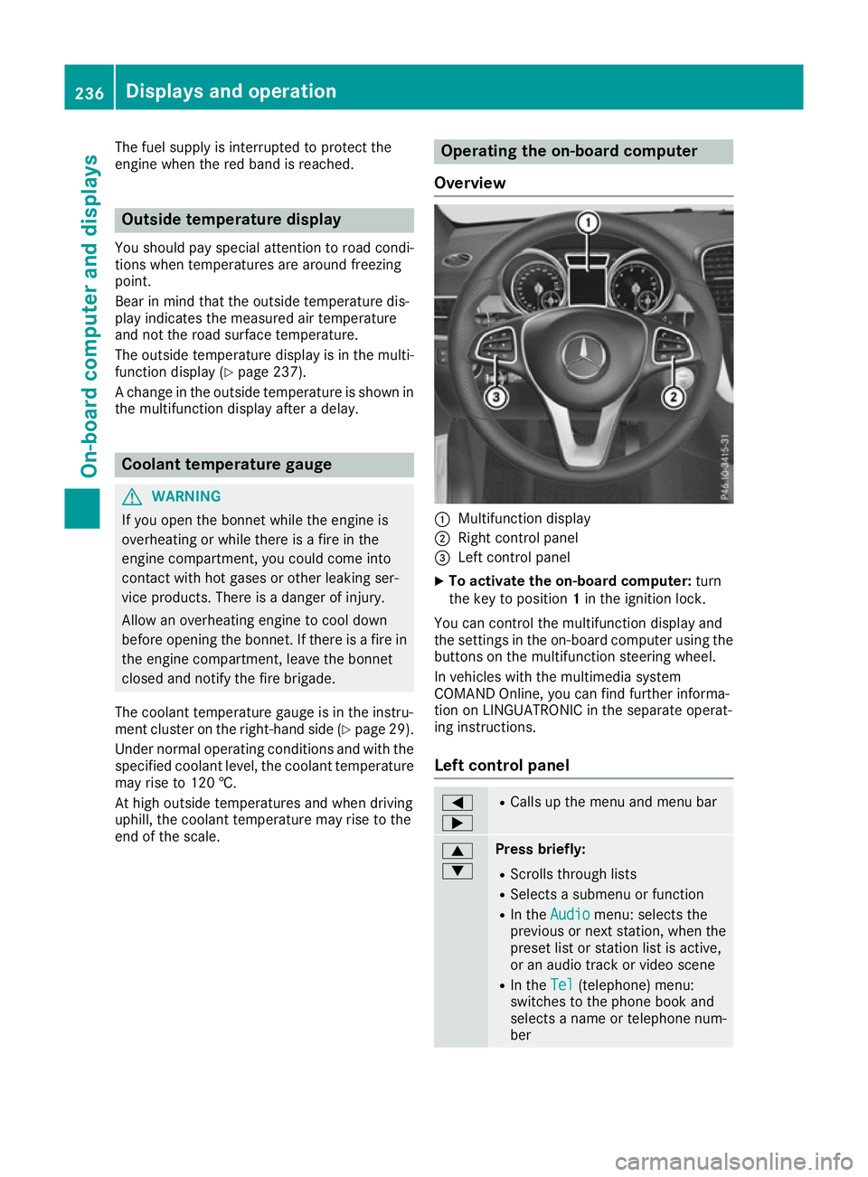
Overview :
Multifunction display
; Right control panel
= Left control panel
X To activate the on-board computer: turn
the key to position 1in the ignition lock.
You can control the multifunction display and
the settings in the on-board computer using the buttons on the multifunction steering wheel.
In vehicles with the multimedia system
COMAND Online, you can find further informa-
tion on LINGUATRONIC in the separate operat-
ing instructions.
Left control panel =
; R
Calls up the menu and menu bar 9
: Press briefly:
R Scrolls through lists
R Selects a submenu or function
R In the Audio Audio menu: selects the
previous or next station, when the preset list or station list is active,
or an audio track or video scene
R In the Tel Tel(telephone) menu:
switches to the phone book and
selects a name or telephone num-
ber 236
Displays and operationOn-board computer and displays
Page 240 of 393
9
: Press and hold:
R
In the Audio Audio menu: selects a pre-
set list or a station list in the
desired frequency range, or
selects an audio track or video
scene using rapid scrolling
R In the Tel
Tel (Telephone) menu:
starts rapid scrolling if the phone
book is open a R
Confirms the selection or display
message
R In the Tel Tel(Telephone) menu:
switches to the telephone book
and starts dialling the selected
number % Press briefly:
R Back
R Switches off voice-operated navi-
gation or LINGUATRONIC
R Hides display messages or calls up
the last Trip Tripmenu function used
R Exits the telephone book/redial
memory % Press and hold:
R
Calls up the standard display in the
Trip
Trip menu Right control panel
~ R
Rejects or ends a call
R Exits the telephone book/redial
memory 6 R
Makes or accepts a call
R Switches to the redial memory W
X R
Adjusts the volume 8 R
Mute ? R
Switches on voice-operated navi-
gation or LINGUATRONIC Multifunction display
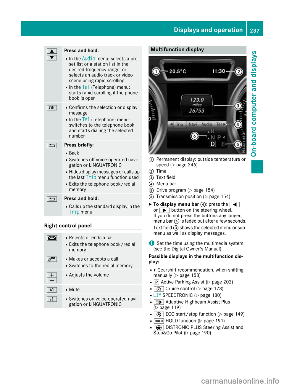
:
Permanent display: outside temperature or
speed (Y page 246)
; Time
= Text field
? Menu bar
A Drive program (Y page 154)
B Transmission position (Y page 154)
X To display menu bar ?: press the=
or ; button on the steering wheel.
If you do not press the buttons any longer,
menu bar ?is faded out after a few seconds.
Text field =shows the selected menu or sub-
menu as well as display messages.
i Set the time using the multimedia system
(see the Digital Owner's Manual).
Possible displays in the multifunction dis-
play:
R ZGearshift recommendation, when shifting
manually (Y page 158)
R j Active Parking Assist (Y page 202)
R ¯ Cruise control (Y page 178)
R LIM
LIM SPEEDTRONIC (Y page 180)
R _ Adaptive Highbeam Assist Plus
(Y page 119)
R è ECO start/stop function (Y page 149)
R ë HOLD function (Y page 191)
R a DISTRONIC PLUS Steering Assist and
Stop&Go Pilot (Y page 190) Displays and operation
237On-board computer and displays Z