MERCEDES-BENZ GLS SUV 2020 Owners Manual
Manufacturer: MERCEDES-BENZ, Model Year: 2020, Model line: GLS SUV, Model: MERCEDES-BENZ GLS SUV 2020Pages: 549, PDF Size: 9.9 MB
Page 391 of 549
#
Make sure that thesteering wheel can
mo vefreely, before towing theve hicle
aw ay. *
NO
TEDama gedue toexcessive tracti ve
po wer If
yo u pull away sharpl y,the tractive po wer
may be too high and theve hicles could be
damaged. #
Pull away slowly and smoo thly. Loading the
vehicle for transport #
Obser vethe no tes on towing away
( / page 386). #
Connect theto w bar totheto wing eye in
order toload theve hicle.
% You can also attach theto w bar tothe trailer
hitch. #
Shift the automatic transmission toposition
i. %
The automatic transmission may be loc ked
in position jintheeve nt of dama getothe
electrics. Toshift toi , pr ovide the on-
board electrical sy stem with po wer
( / page 384). #
Load theve hicle onto the transpor ter. #
Shift the automatic transmission toposition
j. #
Use the electric parking brake tosecure the
ve hicle against rolling away. #
Only secure theve hicle bythe wheels.
Ve hicles with ADS PLUS (Adaptive Damping
Sy stem PLUS) &
WARNING Risk of an accident when
transporting vehicles with Adaptive
Damping Sy stem PLUS
The reduced damping forc es on theve hicle
being transpor ted can cause theve hicle/
trailer combination tostart toswing.
As a result, when transporting vehicles with
th eAd aptive Damping Sy stem PLUS, the ve
hicle/trailer combination may start toskid.
Consequentl y,yo u could lose cont rol of your
ve hicle. #
When transporting, ensure that:
R theve hicle has been loaded onto
th e transpor ter cor rectly
R theve hicle is secured at all four
wheels with suitable tensioning
st ra ps
R the maximum permissible speed of
60 km/h is not exceeded when
transporting *
NO
TEDama getotheve hicle from secur‐
ing it incor rectly #
After loading, theve hicle must be
secured on all four wheels. Otherwise,
th eve hicle could be damaged. #
A minimum dis tance of 20 cm up wards
and 10cm down wards must be kept to
th e transport platform. 388
Breakdown assis tance
Page 392 of 549
#
Secu retheve hicle on all four wheels af ter
loading.
4MATIC vehicles/ vehicles with automatic
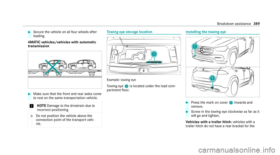
transmission #
Make sure that the front and rear axles come
to rest on the same transpor tation vehicle.
* NO
TEDama getothe driv etra in due to
incor rect positioning #
Do not position theve hicle abo vethe
connection point of the transport vehi‐
cle. To
wing eyesto rage location Example:
towing eye
To wing eye1 is located under the load com‐
partment floor. Installing
theto wing eye #
Press the mark on co ver1 inwa rds and
re mo ve. #
Screw intheto wing eyeclockwise as far as it
will go and tighten.
Ve hicles with a trailer hitch: vehicles with a
trailer hitch do not ha veare ar brac ketfo rthe Breakdown assis
tance 389
Page 393 of 549
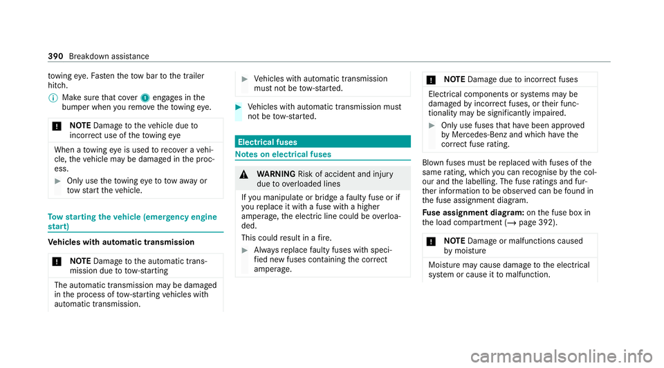
to
wing eye. Fasten theto w bar tothe trailer
hitch.
% Make sure that co ver1 engages in the
bumper when youre mo vetheto wing eye.
* NO
TEDama getotheve hicle due to
incor rect use of theto wing eye When a
towing eye is used toreco ver a vehi‐
cle, theve hicle may be damaged in the proc‐
ess. #
Only use theto wing eyeto to waw ay or
to w start theve hicle. To
w starting theve hicle (eme rgency engine
st art) Ve
hicles with automatic transmission
* NO
TEDama getothe automatic trans‐
mission due to tow-starting The automatic transmission may be damaged
in the process of tow- starting vehicles with
automatic transmission. #
Vehicles with automatic transmission
must not be tow- star ted. #
Vehicles with automatic transmission must
not be tow- star ted. Electrical fuses
Note
s on electrical fuses &
WARNING Risk of accident and inju ry
due to ov erloaded lines
If yo u manipulate or bridge a faulty fuse or if
yo ure place it with a fuse with a higher
amperage, the electric line could be overloa‐
ded.
This could result in a fire. #
Alw aysre place faulty fuses with speci‐
fi ed new fuses conta iningthe cor rect
amperage. *
NO
TEDama gedue toincor rect fuses Electrical components or sy
stems may be
damaged byincor rect fuses, or their func‐
tionality may be significant lyimpaired. #
Only use fuses that ha vebeen appr oved
by Mercedes-Benz and which ha vethe
cor rect fuse rating. Blown fuses mu
stbe replaced with fuses of the
same rating, which you can recognise bythe col‐
our and the labelling. The fuse ratings and fur‐
th er information tobe obser ved can be found in
th e fuse assignment diagram.
Fu se assignment diag ram: onthe fuse box in
th e load compartment (/ page 392).
* NO
TEDama geor malfunctions caused
by moisture Moisture may cause dama
getothe electrical
sy stem or cause it tomalfunction. 390
Breakdown assi stance
Page 394 of 549
#
When the fuse box is open, make sure
th at no moisture can enter the fuse
box. #
When closing the fuse box, make sure
th at the seal of the lid is positioned cor‐
re ctly on the fuse box. If
th e newly inser ted fuse also blo ws, ha vethe
cause traced and rectified at a qualified special‐
ist workshop.
Ensure thefo llowing before replacing a fuse:
R The vehicle is secured against rolling away.
R All electrical consumers are switched off.
R The ignition is switched off.
The electrical fuses are located in various fuse
bo xes:
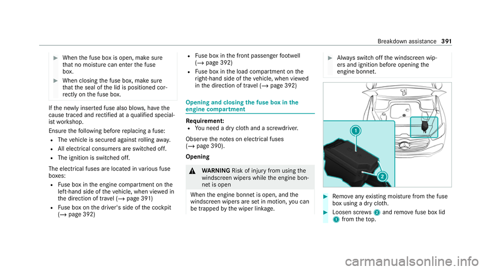
R Fuse box in the engine compartment on the
left-hand side of theve hicle, when vie wed in
th e direction of tr avel (/ page 391)
R Fuse box on the driver's side of the cockpit
(/ page 392) R
Fuse box in the front passenger foot we ll
(/ page 392)
R Fuse box in the load compartment on the
ri ght-hand side of theve hicle, when vie wed
in the direction of tra vel (/ page 392) Opening and closing
the fuse box in the
engine compa rtment Re
quirement:
R You need a dry clo thand a sc rewdriver.
Obser vethe no tes on electrical fuses
(/ page 390).
Opening &
WARNING Risk of inju ryfrom using the
windscreen wipers while the engine bon‐
net is open
When the engine bonn etis open, and the
windscreen wipers are set in motion, you can
be trapped bythe wiper linkage. #
Alw ays switch off the windscreen wip‐
ers and ignition before opening the
engine bonn et. #
Remo veany existing moisture from the fuse
box using a dry clo th. #
Loosen scr ews2 and remo vefuse box lid
1 from theto p. Breakdown assis
tance 391
Page 395 of 549
Closing
#
Check whe ther the seal is positioned cor‐
re ctly in the lid. #
Insert the lid into the brac ket at there ar of
th e fuse box. #
Fold down the lid of the fuse box and tighten
scr ews2. #
Close the bonn et. Opening and closing
the fuse box in the
cockpit The fuse box is on
the driver's side on the side of
th e cockpit under a co ver. #
Con tact a Mercedes-Benz Service Centre for
fur ther information. Opening and closing
the fuse box in the front
passenger foot we ll #
Contact a Mercedes-Benz Service Cent refor
fur ther information. Opening and closing
the fuse box in the load
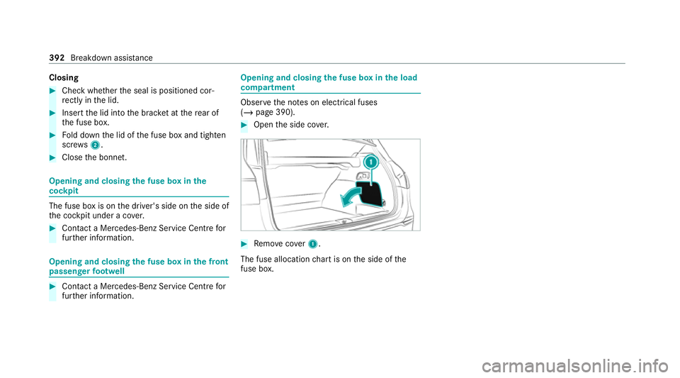
compa rtment Obse
rveth e no tes on electrical fuses
(/ page 390). #
Open the side co ver. #
Remo vecover1.
The fuse allocation chart is on the side of the
fuse box. 392
Breakdown assi stance
Page 396 of 549
Note
s on noise or unusual handling charac‐
te rist ics
Make sure there are no vibrations, noises or
unusual handling characteristics when theve hi‐
cle is in motion. This may indicate that the
wheels or tyres are damaged. Hidden tyre dam‐
age could also be causing the unusual handling
ch aracteristics.
If yo u suspect that a tyre is defective, reduce
yo ur speed immediately and ha vethe tyres and
wheels checked at a qualified specialist work‐
shop. Note
s onregular lyinspecting wheels and
tyres &
WARNING Risk of inju rydue todamaged
tyres
Damaged tyres can cause tyre pressure loss. #
Check the tyres regularly for signs of
dama geand replace any damaged tyres
immediatel y. &
WARNING Risk of aquaplaning due to
insuf ficient tyre tread
Insu fficient tyre tread will result in reduced
tyre grip.
The risk of aquaplaning is increased on wet
ro ads, especially when the speed of theve hi‐
cle is not adap tedto suit the conditions. #
Thus, you should regularly check the
tread de pth and the condition of the
tread across the entire width of all
tyres.
Minimum tread dep thfor:
R Summer tyres: 3 mm
R M+S tyres: 4 mm #
For saf etyre asons, replace the tyres
before the legally-prescribed limit for
th e minimum tread dep thisreached. Car
ryout thefo llowing checks on all wheels reg‐
ularly, at least once a month or as requ ired, for
ex ample, prior toa long journey or driving off-
ro ad:
R Check the tyre pressure (/ page 394).
R Visually inspect wheels and tyres for dam‐
age.
R Check theva lve caps.
R Visual check of the tyre tread dep thand the
tyre contact su rface across the entire width.
The minimum tread dep thfor summer tyres
is 3 mm and for winter tyres 4 mm. Note
s on snow chains &
WARNING Risk of accident due toincor‐
re ct snow chain fitting
If yo u ha vefitted snow chains tothe front
wheels, the snow chains may drag against
th eve hicle body or chassis components.
This could cause damage totheve hicle or
th e tyres. Wheels and tyres
393
Page 397 of 549
#
Neverfit snow chains on the front
wheels. #
Only fit snow chains on there ar wheels
in pairs. *
NO
TEDama getocomponents of the
ve hicle body or chassis due tofitted
snow chains If
yo ufit snow chains tothe front wheels of
4MATIC vehicles, you may damage co mpo‐
nents of theve hicle body or chassis. #
Onlyfit snow chains tothere ar wheels
of 4MATIC vehicles. R
Snow chains are on ly permissible for cer tain
wheel/tyre combinations. You can obtain
information about this from a Mercedes-Benz
Service Cent re.
R For saf etyre asons, on lyuse sn owchains that
ha ve been specifically appr ovedfo ryo ur
ve hicle byMercedes-Benz, or snow chains
with the same quality standard. R
If sn owchains are fitted, the maximum per‐
missible speed is 50 km/h.
R Vehicles with Active Parking Assis t:do
not use Active Parking Assist when snow
ch ains are fitted.
R Vehicles with AIRMATIC or E- ACTIVE
BO DY CONT ROL:if sn ow ch ains are fitted,
only drive at raised vehicle le vel .
% You can permanently limit the maximum
ve hicle speed for driving with winter tyres
(/ page 236).
% You can deactivate ESP ®
to pull away
( / page 229). This allo wsthe wheels to
spin, achieving an increased driving forc e. Ty
re pressure Note
s on tyre pressure &
WARNING Risk of accident due toinsuf‐
fi cient or excessive tyre pressure
Ty res with either too low or too high a pres‐
sure present thefo llowing hazards:
R the tyres could bur st
R the tyres could wearexcessively and/or
une venly
R the driving characteristics as well as
st eering and braking characteristics may
be se verely impaired #
Obse rveth ere commended tyre pres‐
su res and check the tyre pressures of
all tyres including the spare wheel:
R monthly
R if altering the load on theve hicle
R prior tolong journe ys
R ifth e operating conditions change, for
ex ample when driving off- road 394
Wheels and tyres
Page 398 of 549
#
Adjust the tyre pressure where neces‐
sar y. Ty
re pressure which is too high or too low can:
R Shor tenth e service life of the tyres.
R Cause increased tyre damage.
R Adversely af fect driving characteristics and
th us driving saf ety, e.g. due toaquaplaning. &
WARNING Risk of accident due torepea‐
te d pressure drop in the tyres
The wheels, valves or tyres could be dam‐
aged.
To o low a tyre pressure can lead tothe tyres
bur sting. #
Examine the tyres forfo re ign objects. #
Check whe ther the tyre has a puncture
or theva lve has a leak. #
Ifyo u are unable torectify the damage,
conta ct aqualified specialist workshop. Information on
there commended tyre pressure
fo rth eve hicle's factor y-fitted tyres can be found on
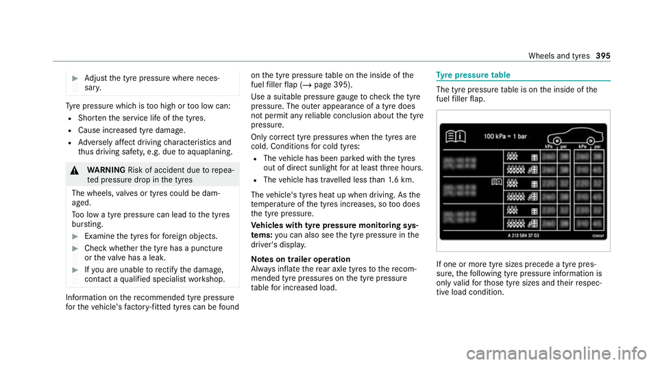
the tyre pressure table on the inside of the
fuel filler flap (/ page 395).
Use a suitable pressure gauge tocheck the tyre
pressure. The outer appearance of a tyre does
not permit any reliable conclusion about the tyre
pressure.
Only cor rect tyre pressures when the tyres are
cold. Conditions for cold tyres:
R The vehicle has been par ked with the tyres
out of direct sunlight for at least thre e hours.
R The vehicle has tr avelled less than 1.6 km.
The vehicle's tyres heat up when driving. As the
te mp erature of the tyres increases, so too does
th e tyre pressure.
Ve hicles with tyre pressure monitoring sys‐
te ms: you can also see the tyre pressure in the
driver's displa y.
Note s on trailer operation
Alw ays inflate there ar axle tyres tothere com‐
mended tyre pressures on the tyre pressure
ta ble for increased load. Ty
re pressure table The tyre pressure
table is on the inside of the
fuel filler flap. If one or more tyre sizes precede a tyre pres‐
sure, thefo llowing tyre pressure information is
only valid forth ose tyre sizes and their respec‐
tive load condition. Wheels and tyres
395
Page 399 of 549
If
th e preceding tyre sizes are complemented by
th e+ symbol, the tyre pressure information
fo llowing sho wsalternative tyre pressures. Fuel
consum ption may then increase slightl y.
The load conditions "partially laden" and "fully
laden" are defined in theta ble for dif fere nt num‐
be rs of passengers and amounts of luggage. The
actual number of seats may dif fer from this. Ty
re pressure moni toring sy stem Fu
nction of the ty repressure moni toring sys‐
tem
The sy stem checks the tyre pressure and the
tyre temp erature of the tyres fitted totheve hicle
by means of a tyre pressu resensor.
The tyre pressure and the tyre temp erature
appear in the on-board computer (/ page 396).
If th ere is a subs tantial pressure loss or if the
tyre temp erature is excessive, you will be
wa rned in thefo llowing ways:
R via display messa ges (/ page 482).
R viatheh warning lamp in the instrument
clus ter (/ page 504) The tyre pressu
remonitoring sy stem is only an
aid. It is the driver's responsibility toset the tyre
pressure tothere commended cold tyre pressure
suitable forth e operating situation.
In most cases, the tyre pressure monitoring sys‐
te m will auto maticallyupdate the new refere nce
va lues af teryo u ha vechanged the tyre pressure.
Yo u can, ho wever,also update there fere nce val‐
ues byrestarting the tyre pressure monitoring
sy stem manually (/ page 397).
Sy stem limits
The sy stem may be impaired or may not function
particular lyin thefo llowing situations:
R the tyre pressure has been set incor rectly
R sudden pressure loss caused byafo re ign
object penetrating the tyre, forex ample
R there is a malfunction caused byano ther
ra dio signal source
Checking the ty repressure with the tyre
pressure moni toring sy stem
Re quirements:
R The ignition is switched on. On-board computer:
4 Service 5
Tyres
One of thefo llowing displa ysappears:
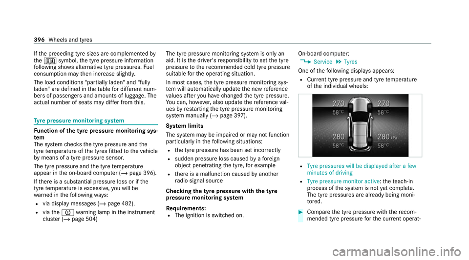
R Cur rent tyre pressure and tyre temp erature
of the individual wheels: R
Tyre pressures will be displayed after a few
minutes of driving
R Tyre pressure monitor active: thete ach-in
process of the sy stem is not yet compl ete.
The tyre pressures are already being moni‐
to re d. #
Compare the tyre pressure with there com‐
mended tyre pressure forth e cur rent operat‐ 396
Wheels and tyres
Page 400 of 549
ing condition (/
page 395). Observethe
no tes on tyre temp erature (/ page 394).
% The values displa yed in the on-board com‐
puter may deviate from those of the tyre
pressure gauge as they referto sea le vel.At
high ele vations, the tyre pressure values
indicated bya pressure gauge are higher
th an those shown bythe on-board computer.
In this case, do not reduce the tyre pressure.
Re starting the ty repressure moni toring sys‐
tem
Re quirements:
R The recommended tyre pressure is cor rectly
set forth ere spective operating status on all
of the wheels (/ page 394).
Re start the tyre pressure monitoring sy stem in
th efo llowing situations:
R The tyre pressure has changed.
R The wheels or tyres ha vebeen changed or
newly fitted. On-boa
rdcompu ter:
4 Service 5
Tyres #
Swipe down wards on Touch Control on the
left-hand side of thesteering wheel.
The Use current pressures as new reference
values? message is shown in the multifunc‐
tion displa y. #
Torestart, press Touch Control on the left-
hand side of thesteering wheel.
The Tyre press. monitor restarted message is
shown in the multifunction displa y.
Cur rent wa rning messages are dele ted and
th eye llow h warning lamp goes out.
Af teryo u ha vebeen driving for a few
minutes, the sy stem checks whe ther the cur‐
re nt tyre pressures are wi thin the specified
ra nge. The cur rent tyre pressures are then
accep ted as refere nce values and monitored.
Be sure toalso pay attention tothefo llowing
re lated topic:
R Notes on tyre pressure (/ page 394) Wheel
change Note
s on selecting, fitting and replacing
tyres *
NO
TEMercedes-AMG vehicles #
Obser vethe no tes in the Supplement.
Yo u could otherwise failto recognise
dangers. &
WARNING Risk of accident due toincor‐
re ct dimensions of wheels and tyres
If wheels and tyres of the wrong size are
used, the wheel brakes or wheel suspension
components may become damaged. #
Alw aysre place wheels and tyres with
th ose that fulfil the specifications of the
original part.
When replacing wheels, make sure tofit the
cor rect:
R Designation
R Type Wheels and tyres
397