emergency towing MERCEDES-BENZ M-Class 2011 W164 Owner's Manual
[x] Cancel search | Manufacturer: MERCEDES-BENZ, Model Year: 2011, Model line: M-Class, Model: MERCEDES-BENZ M-Class 2011 W164Pages: 372, PDF Size: 16.23 MB
Page 6 of 372
1, 2, 3 ...
115 V socket ...................................... 269
12 V socket ........................................ 268
4ETS see ETS/4ETS
4MATIC (permanent four-wheel
drive) .................................................. 191
A
ABS (Anti-lock Braking System) Display message ............................ 228
Function/notes ................................ 65
Warning lamp ................................. 249
Accident (notes) ................................ 297
Active light function (display
message) ............................................ 233
Active service system see Service interval display
Adaptive Damping System (ADS) ..... 184
AdBlue ®
Adding ........................................... 156
Display message ............................ 236
Additional functions (on-board
computer) .......................................... 219
ADS (Adaptive Damping System) ..... 184
Air bags Display message ............................ 225
Front air bag (driver, front
passenger) ....................................... 39
Important safety information ...........38
PASSENGER AIRBAG OFF
indicator lamp (only Canada) ...........48
PASSENGER AIRBAG OFF
indicator lamp (only USA) ................42
Safety guidelines ............................. 37
Side impact air bag ..........................40
Window curtain air bag ....................41
Air-conditioning system
see Climate control
Air dehumidification
Activating/deactivating with
cooling ........................................... 129
Air distribution
Setting ........................................... 132
Air filter (display message) .............. 236
Airflow
Setting ........................................... 132
AIRMATIC package ............................ 183
Air nozzles see Air vents .................................. 135
Air pressure
see Tire pressure
Air-recirculation mode
Activating/deactivating .................133
Air vents ............................................. 135
Important safety information .........134
Rear ............................................... 135
Setting the center air vents ...........135
Setting the side air vents ...............135
Alarm system
see ATA
Ambient lighting (on-board
computer) .......................................... 216
AMG menu (on-board computer) ..... 209
Anti-lock Braking System see ABS
Anti-Theft Alarm system
see ATA
Anti-theft system
ATA (Anti-Theft Alarm system) .........69
Approach/departure angle .............. 170
Ashtray ............................................... 267
ATA (Anti-Theft Alarm system) Activating/deactivating ...................69
Function ........................................... 69
Switching off the alarm ....................69
Audio menu (on-board computer) .... 211
AUTO lights see Light sensor
Automatic car wash .......................... 288
Automatic transmission DIRECT SELECT lever .....................144
Display message ............................ 243
Driving tips .................................... 147
Emergency running mode ..............151
Kickdown ....................................... 147
Malfunction .................................... 151
Program selector button ................147
Pulling away ................................... 141
Starting .......................................... 141
Trailer towing ................................. 1474IndexBA 164.1 USA, CA Edition B 2011; 1; 2, en-USd2mskotVersion: 3.0.3.52010-04-21T17:25:06+02:00 - Seite 4
Page 10 of 372
PARKTRONIC ................................. 184
Rear view camera .......................... 187
Driving tip
Braking .......................................... 163
Driving tips ........................................ 147
DISTRONIC .................................... 179
Downhill gradients .........................161
Driving on flooded roads ................164
Driving on sand .............................. 168
Driving over obstacles ...................169
Off-road driving .............................. 167
Off-road fording ............................. 164
Tire ruts ......................................... 169
Towing a trailer .............................. 198
Wet road surface ........................... 162
Winter ............................................ 166
DSR (Downhill Speed
Regulation) ......................................... 192
Display message ............................ 239
Setting (on-board computer) .......... 219
DVD audio (on-board computer) ...... 212
E
EASY-ENTRY feature ......................... 100
Activating/deactivating (on-
board computer) ............................ 218
EASY-EXIT feature ............................. 100
Crash-responsive ........................... 101
EASY-PACK cargo compartment
management system ........................ 263
EASY-PACK load-securing kit ........... 263
EBD (Electronic Brake force
Distribution) Display message ............................ 229
Function/notes ................................ 68
Electrical fuses
see Fuses
Electronic Brake-force
Distribution) see EBD
Electronic Stability Program
see ESP ®
Electronic Traction System
see ETS/4ETS
Emergency call
see mbrace
Emergency release
Fuel filler flap ................................. 153
Vehicle ............................................. 80
Emergency running mode
Automatic transmission .................151
Emergency spare wheel
Storage location ............................ 299
Stowing .......................................... 299
Emergency tensioning device
Function ........................................... 57
Safety guidelines ............................. 37
Emergency unlocking
Tailgate ............................................ 84
Emissions purification
Service and warranty information ....19
Engine
Irregular running ............................ 143
Starting problems ..........................143
Starting the engine with the key ....141
Starting with KEYLESS GO .............141
Switching off .................................. 158
Warning lamp (engine
diagnostics) ................................... 252
Engine electronics
Malfunction .................................... 143
Engine emergency stop .................... 322
Engine number .................................. 356
Engine oil Adding ........................................... 284
Checking the oil level ..................... 283
Display message ............................ 235
Lubricant additives ........................361
Notes about oil grades ................... 361
Temperature (on-board computer) . 209
Viscosity ........................................ 361
ESP ®
(Electronic Stability
Program) Activating/deactivating ...................67
Display message ............................ 223
ETS/4ETS ........................................ 67
Important safety information ...........66
Trailer stabilization ........................... 68
Warning lamp ................................. 250
ETS/4ETS (Electronic Traction
System) ................................................ 67
Exhaust check ................................... 1618IndexBA 164.1 USA, CA Edition B 2011; 1; 2, en-USd2mskotVersion: 3.0.3.52010-04-21T17:25:06+02:00 - Seite 8
Page 16 of 372
Belt force limiters ............................ 57
Cleaning ......................................... 293
Correct usage .................................. 54
Emergency Tensioning Devices ........ 57
Fastening ......................................... 55
Important safety guidelines .............53
Releasing ......................................... 56
Safety guidelines ............................. 37
Switching belt adjustment on/off
(on-board computer) ......................218
Warning lamp ................................. 248
Warning lamp (function) ................... 57
Seat heating
Indicator lamp (Malfunction) ............98
Seats
Adjusting (electrically) .....................94
Adjusting the 4-way lumbar
support ............................................ 97
Adjusting the head restraint ............95
Cleaning the cover .........................292
Correct driver's seat position ........... 92
Important safety instructions ...........93
Multicontour seat ............................ 97
Storing settings (memory
function) ........................................ 103
Switching seat heating on/off .........97
Switching the seat ventilation on/
off .................................................... 98
Seat ventilation
Indicator lamp (Malfunction) ............99
Securing hooks .................................. 260
Sensors (cleaning instructions) ....... 291
Service indicator see Service interval display
Service interval display .................... 287
Displaying a service message (on-
board computer) ............................ 287
Service products
AdBlue ®
special additives ..............360
Brake fluid ..................................... 362
Coolant (engine) ............................ 362
Engine oil ....................................... 361
Filling capacity ............................... 357
Fuel ................................................ 358
Important safety notes ..................356
Notes ............................................. 356Refrigerant (air-conditioning
system) .......................................... 362
Washer fluid ................................... 363
Settings
Factory (on-board computer) .........213
On-board computer .......................213
Shift ranges ....................................... 148
Side impact air bag ............................. 40
Side marker lamp (display
message) ............................................ 232
Side windows Convenience closing feature ............86
Convenience opening feature ..........86
Important safety information ...........84
Opening/closing .............................. 85
Resetting ......................................... 87
Troubleshooting ............................... 87
Sliding sunroof
Important safety information ...........88
Troubleshooting ............................... 89
see Tilt/sliding sunroof
SmartKey
Changing the battery .......................76
Changing the programming .............75
Checking the battery .......................76
Important safety notes ....................72
Malfunction ...................................... 77
Snow chains ...................................... 165
Socket ................................................ 268
Dashboard ..................................... 268
Front-passenger footwell ...............268
Luggage compartment ...................269
Rear compartment .........................269
SOS
see mbrace
Spare wheel
Notes/data .................................... 352
Storage location ............................ 299
Stowing .......................................... 299
see Emergency spare wheel
Speedometer
Additional speedometer (on-
board computer) ............................ 208
Segments ...................................... 205
Setting the unit (on-board
computer) ...................................... 21414IndexBA 164.1 USA, CA Edition B 2011; 1; 2, en-USd2mskotVersion: 3.0.3.52010-04-21T17:25:06+02:00 - Seite 14
Page 19 of 372
Total load limit (definition) .............347
Traction ......................................... 339
Traction (definition) .......................346
Tread wear ..................................... 339
TWR (permissible trailer drawbar
noseweight) (definition) .................347
Uniform tire quality classification
standards (definition) .....................344
Unladen weight (definition) ............345
Wear indicator (definition) .............347
Wheel rim (definition) ....................345
Tires and wheels (important safety
information) ....................................... 324
Top Tether ............................................ 62
Towing Important safety guidelines ...........317
Towing a trailer
Driving tips .................................... 198
Towing away
Installing the towing eye ................318
Removing the towing eye ...............319
Trailer
Coupling up ................................... 198
Decoupling ..................................... 200
Display message ............................ 230
Power supply ................................. 201
Towing ........................................... 199
Trailer loads and drawbar
noseweights ...................................... 200
Trailer towing .................................... 147
Blind Spot Assist ............................ 191
ESP ®
................................................ 68
PARKTRONIC ................................. 186
Transfer case ..................................... 151
Transmission position display ......... 145
Transmission positions .................... 146
Traveling uphill Brow of hill ..................................... 171
Driving downhill ............................. 171
Maximum gradient-climbing
capability ....................................... 170
Trip computer (on-board
computer) .......................................... 219
Trip odometer Calling up ....................................... 208
Resetting (on-board computer) ......220Trunk
Automatic opening ..................... 82, 83
Turn signal (display message) ......... 230
Turn signals ....................................... 109
TWR (permissible trailer drawbar
noseweight) (definition) ................... 347
Type plate see Vehicle identification plate
U
Unlocking Emergency unlocking .......................80
From inside the vehicle (central
unlocking button) ............................. 79
V
Vanity mirror Sun visor ........................................ 266
Vehicle
Data acquisition ............................... 23
Emergency release ..........................80
Equipment ....................................... 19
Exterior view .................................... 26
Individual settings (on-board
computer) ...................................... 213
Loading .......................................... 334
Lowering ........................................ 310
Maintenance .................................... 20
Parking up ..................................... 159
Raising ........................................... 306
Reporting problems .........................22
Towing away .................................. 317
Tow-starting ................................... 317
Transporting .................................. 319
Vehicle data
see Technical data
Vehicle identification number
see VIN
Vehicle identification plate .............. 355
Vehicle tool kit .................................. 298
Video (DVD) ........................................ 212
Video DVD (on-board computer) ...... 212
VIN ...................................................... 355
Index17BA 164.1 USA, CA Edition B 2011; 1; 2, en-USd2mskotVersion: 3.0.3.52010-04-21T17:25:06+02:00 - Seite 17
Page 271 of 372
XPress marking =.
Stowage compartment : opens.XRemove cover from socket ;.
i
On vehicles with the smoker's package,
you must remove the cigarette lighter in
order to use the socket ( Y page 267).
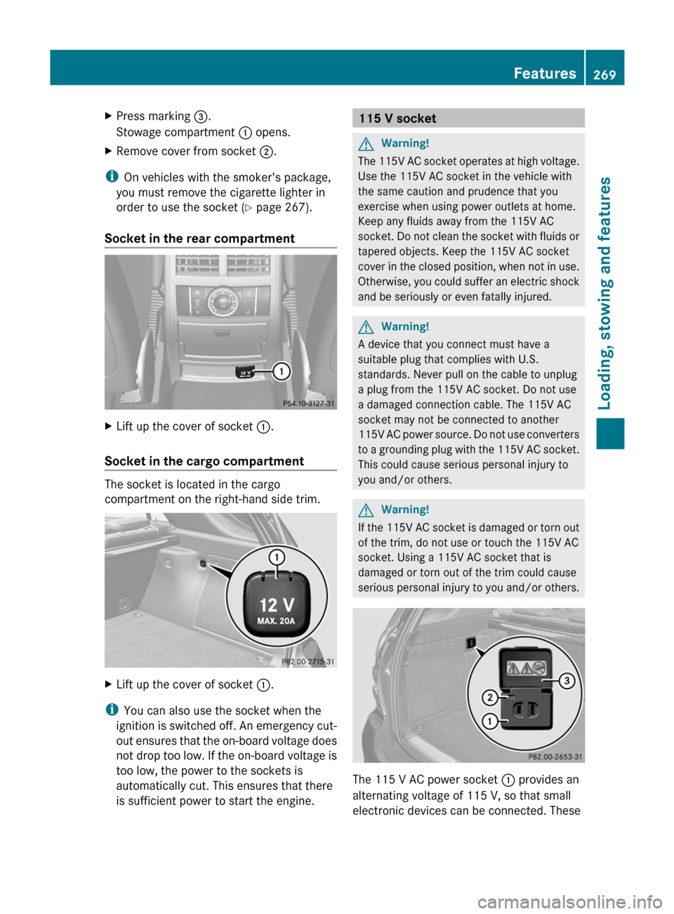
Socket in the rear compartment
XLift up the cover of socket :.
Socket in the cargo compartment
The socket is located in the cargo
compartment on the right-hand side trim.
XLift up the cover of socket :.
i
You can also use the socket when the
ignition is switched off. An emergency cut-
out ensures that the on-board voltage does
not drop too low. If the on-board voltage is
too low, the power to the sockets is
automatically cut. This ensures that there
is sufficient power to start the engine.
115 V socketGWarning!
The 115V AC socket operates at high voltage.
Use the 115V AC socket in the vehicle with
the same caution and prudence that you
exercise when using power outlets at home.
Keep any fluids away from the 115V AC
socket. Do not clean the socket with fluids or
tapered objects. Keep the 115V AC socket
cover in the closed position, when not in use.
Otherwise, you could suffer an electric shock
and be seriously or even fatally injured.
GWarning!
A device that you connect must have a
suitable plug that complies with U.S.
standards. Never pull on the cable to unplug
a plug from the 115V AC socket. Do not use
a damaged connection cable. The 115V AC
socket may not be connected to another
115V AC power source. Do not use converters
to a grounding plug with the 115V AC socket.
This could cause serious personal injury to
you and/or others.
GWarning!
If the 115V AC socket is damaged or torn out
of the trim, do not use or touch the 115V AC
socket. Using a 115V AC socket that is
damaged or torn out of the trim could cause
serious personal injury to you and/or others.
The 115 V AC power socket : provides an
alternating voltage of 115 V, so that small
electronic devices can be connected. These
Features269Loading, stowing and featuresBA 164.1 USA, CA Edition B 2011; 1; 2, en-USd2mskotVersion: 3.0.3.52010-04-21T17:25:06+02:00 - Seite 269Z
Page 273 of 372
The mbrace system
The mbrace system provides three different
services:
R automatic and manual emergency call
R Roadside Assistance call
R MB info call
To control the volume during an mbrace call,
proceed as follows:
XPress the W or X button on the
multifunction steering wheel.
or
XUse the volume controller of the audio
system/COMAND.
You can find information and a description of
all available features under "Owners Online"
at http://www.mbusa.com 40
System self-test
After you have switched on the ignition, the
system carries out a self-diagnosis.
GWarning
A malfunction in the system has been
detected if any or all of the following
conditions occur:
R The indicator lamp in the SOS button does
not come on during the system self-test.
R The indicator lamp in Roadside Assistance
button º does not come on during the
system self-test.
R The indicator lamp in Information button
E does not come on during the system
self-test.
R The indicator lamp in the SOS button,
Roadside Assistance button º, or
Information button E remains
illuminated constantly in red after the
system self-test.
R The message Tele Aid Inoperative or
Tele Aid Not Activated appears in the
multifunction display after the system self-
test.
If a malfunction is indicated as outlined above,
the system may not operate as expected. In
case of an emergency, help will have to be
summoned by other means.
Have the system checked at the nearest
authorized Mercedes-Benz Center or contact
the following service hotlines:
R USA: Response Center under the number
866-990-9007
R Canada: Customer Service under
1-888-923-8367
Emergency call
Important safety notes
! A license agreement must exist in order
to activate the mbrace service. Make sure
that your system is activated and ready for
use, and press the E MB info call button
to register. If you cannot carry out any of
the steps mentioned, the system may not
be activated.
If you have any questions concerning
activation, please contact one of the
following service hotlines:
R USA: Response Center under
866-990-9007
R Canada: Customer Service under
1-888-923-8367
An emergency call is dialed automatically if
an air bag or Emergency Tensioning Device is
triggered.
i An automatically dialed mbrace
emergency call cannot be canceled.
An emergency call can also be dialed
manually.
Once the emergency call is in progress, the
indicator lamp in the SOS button flashes. The
Connecting Call message appears in the
multifunction display.
40 USA only.Features271Loading, stowing and featuresBA 164.1 USA, CA Edition B 2011; 1; 2, en-USd2mskotVersion: 3.0.3.52010-04-21T17:25:06+02:00 - Seite 271Z
Page 274 of 372

COMAND is muted.
Once a connection has been established, the
Call Connected message appears in the
multifunction display.
All important information on the emergency
is compiled, for example:
R current location of the vehicle (as
determined by the GPS system)
R vehicle model
R vehicle color
R vehicle identification number
A voice connection between the Response
Center and the occupants of the vehicle will
be established automatically soon after the
emergency call has been initiated. If the
vehicle occupants are able to respond, the
Response Center will attempt to obtain more
detailed information on the emergency.
i If no vehicle occupant answers, an
ambulance is immediately sent to the
vehicle.GWarning
If the indicator lamp in the SOS button is
flashing continuously and there was no voice
connection to the Response Center
established, then the mbrace system could
not initiate an emergency call (e.g. the
relevant cellular phone network is not
available).
The message Call Failed appears in the
multifunction display for approximately
10 seconds.
Should this occur, assistance must be
summoned by other means.
Making an emergency callXTo initiate an emergency call
manually: press cover : briefly to open.XPress SOS button ; briefly.
The indicator lamp in SOS button ;
flashes until the emergency call is ended.XWait for the voice connection with the
Response Center.XAfter the emergency call is ended, close
cover :.GWarning
If you feel at any way in jeopardy when in the
vehicle (e.g. smoke or fire in the vehicle,
vehicle in a dangerous road location), please
do not wait for voice contact after you have
pressed the SOS button. Carefully leave the
vehicle and move to a safe location. The
Response Center will automatically contact
local emergency officials with the vehicle's
approximate location if they receive an
automatic SOS signal and cannot make voice
contact with the vehicle occupants.
Roadside Assistance call button
XOpen the stowage compartment under the
armrest ( Y page 257).272FeaturesLoading, stowing and features
BA 164.1 USA, CA Edition B 2011; 1; 2, en-USd2mskotVersion: 3.0.3.52010-04-21T17:25:06+02:00 - Seite 272
Page 276 of 372
XPress and hold MB info call button : for
more than two seconds.
A call to the Response Center is initiated.
MB info call button indicator lamp :
flashes while the connection is being
established. The Connecting Call
message appears in the multifunction
display and COMAND is muted.
If a connection can be established, the Call
Connected message appears in the
multifunction display.
If a mobile phone network is available and
there is sufficient GPS reception, the mbrace
system transmits data to the Response
Center, for example:
R current location of the vehicle
R vehicle identification number
R vehicle model
R vehicle color
i The COMAND display shows that an
mbrace call is active. You can switch to the
navigation menu by pressing the NAVI
button on COMAND during the call. Spoken
commands are not available.
A voice connection between the Response
Center and the vehicle occupants is
established. You can obtain information on
how to operate your vehicle's systems, on the
location of the nearest authorized Mercedes-
Benz Center, and on further products and
services offered by Mercedes-Benz USA.
Further details on the mbrace system can be
found under http://www.mbusa.com 42
.
Log in under "Owners Online".
i If the indicator lamp in MB info call
button : flashes continuously and no
voice connection to the Response Center
has been established, then the mbrace
system has failed to initiate an MB info call
(e.g. the corresponding mobile phone
network is not available). The Call
Failed message appears in the
multifunction display.
XTo end a call: press the ~ button on the
multifunction steering wheel.
or
XPress the corresponding button for ending
a phone call on COMAND.
Call priority
An emergency call can still be initiated even
if a service call is currently active, e.g. the
Roadside Assistance call or the MB info call.
In this case, an emergency call will take
priority and override all other active calls.
The indicator lamp of the respective button
flashes until the call is ended. An emergency
call can only be ended by the Mercedes-Benz
Customer Assistance Center. All other calls
can be ended by pressing the ~ button on
the multifunction steering wheel or the
corresponding button for ending a telephone
call on COMAND.
i When an mbrace call has been initiated,
COMAND is muted. The cellular phone is no
longer connected to COMAND. If you must
use your mobile phone, we recommend
that you do this only when the vehicle is
stationary and in a safe location.
Downloading destinations in COMAND
i Information on the components and
operating principles of COMAND can be
found in the separate COMAND operating
instructions.
Destination Download gives you access to a
database with over 10 million points of
interest (POIs) which can be downloaded onto
the navigation system of your vehicle. If you
know the destination, you can download the
address or obtain the location of points of
interest (POIs) or important destinations in
the surrounding area.
42 USA only.274FeaturesLoading, stowing and features
BA 164.1 USA, CA Edition B 2011; 1; 2, en-USd2mskotVersion: 3.0.3.52010-04-21T17:25:06+02:00 - Seite 274
Page 300 of 372

Vehicle tool kit
Notes
The vehicle tool kit can be found in the
stowage well under the cargo compartment
floor.
i Vehicles without a spare wheel are not
equipped at the factory with the tools
needed to change a wheel, e.g. a jack or lug
wrench. Some tools for changing a wheel
are specific to the vehicle. To obtain tools
approved for your vehicle, visit a qualified
specialist workshop, e.g. an authorized
Mercedes-Benz Center.
Folding the cargo compartment floor up
XPress release handle ; in the direction of
the arrow.XLift cargo compartment floor : up by
release handle ;.XFold out hook = on the underside of the
cargo compartment floor.XAttach hook = to upper seal ? in the
cargo compartment.
Vehicles with a TIREFIT kit
XLift the cargo compartment floor up
( Y page 298).:Towing eye;Alignment bolt=Jack?Fuse allocation chartAElectric air pump 44BTIREFIT kit44CLug wrenchDFolding wheel chockERatchet ring spanner
Vehicles with a "Minispare" emergency
spare wheel/collapsible spare wheel
XLift the cargo compartment floor up
( Y page 298).44
Vehicles with BlueTEC 4MATIC (vehicles for Canada) are only available from the factory with 20" wheels.298Where will I find...?Roadside assistance
BA 164.1 USA, CA Edition B 2011; 1; 2, en-USd2mskotVersion: 3.0.3.52010-04-21T17:25:06+02:00 - Seite 298
Page 301 of 372

Example: vehicles with a collapsible spare wheel
:Electric air pump45;Stowage well=Alignment bolt?Towing eyeALug wrenchXRemove the "Minispare" emergency spare
wheel or the collapsible spare wheel.
Example: vehicles with a collapsible spare wheel
BJackCFolding wheel chockDFuse allocation chartEWheel bolts 46FRatchet ring spanner"
Minispare" emergency spare wheel/
collapsible emergency spare wheel
Removing the "Minispare" emergency
spare wheel/collapsible spare wheel
The emergency spare wheel is under the
cargo compartment floor.
XLift the cargo compartment floor up
( Y page 298).XDepending on the vehicle's equipment,
remove the stowage tray from the
emergency spare wheel.
Example: collapsible spare wheel
XTurn emergency spare wheel retainer :
counter-clockwise and remove it.XRemove the "Minispare" emergency spare
wheel or collapsible spare wheel ;.
For further information on changing a wheel
and mounting the spare wheel, see
( Y page 305).
Stowing a used collapsible spare wheel
Take the following steps to stow a used
collapsible spare wheel. It will otherwise not
fit in the spare wheel well. Mercedes-Benz
recommends that you have this work carried
out at a qualified specialist workshop, e.g. an
authorized Mercedes-Benz Center.
! Only place the collapsible spare wheel in
the vehicle when it is dry. Otherwise,
moisture may get into the vehicle.
45 Only vehicles with a "Minispare" emergency spare wheel or a collapsible spare wheel.
46 Only vehicles with a "Minispare" emergency spare wheel.Where will I find...?299Roadside assistanceBA 164.1 USA, CA Edition B 2011; 1; 2, en-USd2mskotVersion: 3.0.3.52010-04-21T17:25:06+02:00 - Seite 299Z