wheel MERCEDES-BENZ METRIS 2016 MY16 Operator’s Manual
[x] Cancel search | Manufacturer: MERCEDES-BENZ, Model Year: 2016, Model line: METRIS, Model: MERCEDES-BENZ METRIS 2016Pages: 310, PDF Size: 7.28 MB
Page 291 of 310
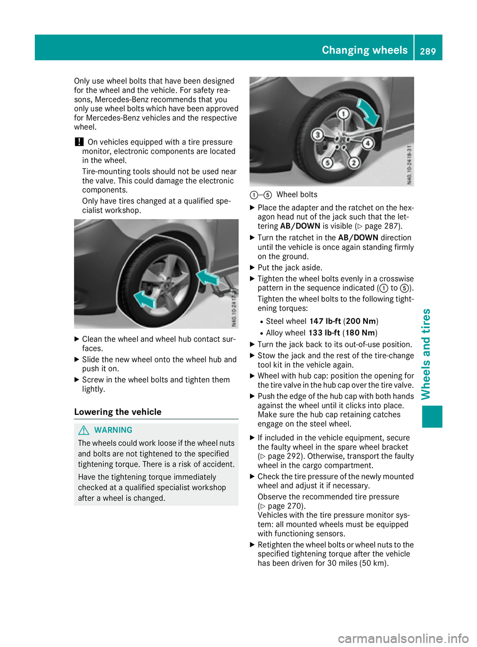
Only use wheel bolts that have been designed
for the wheel and the vehicle. For safety rea-
sons, Mercedes-Benz recommends that you
only use wheel bolts which have been approved
for Mercedes-Benz vehicles and the respective
wheel.
!On vehicles equipped withatire pressure
monitor, electronic componentsa re located
in the wheel.
Tire-mounting tools should not be used near
the valve. This could damage the electronic
components.
Only have tires changed at aqualified spe-
cialist workshop.
XCleant he wheel and wheel hub contact sur-
faces.
XSlide the new wheel onto the wheel hub and
push it on.
XScrew in the wheel bolts and tighten them
lightly.
Lowering the vehicle
GWARNING
The wheels could work loose if the wheel nuts and bolts are not tightened to the specified
tightening torque. There is arisk of accident.
Have the tightening torque immediately
checked at aqualified specialist workshop
after awheel is changed.
:—AWheel bolts
XPlace the adapter and the ratchet on the hex-
agon head nut of the jack such that the let-
tering AB/DOWN is visible (
Ypage 287).
XTurn the ratchet in the AB/DOWNdirection
until the vehicle is once agains tanding firmly
on the ground.
XPut the jack aside.
XTighten the wheel bolts evenly in acrosswise
pattern in the sequence indicated (: toA).
Tighten the wheel bolts to the following tight-
ening torques:
RSteel wheel 147 lb-ft(200 Nm)
RAlloy wheel 133 lb-ft(180 Nm)
XTurn the jack back to its out-of-use position.
XStow the jack and the rest of the tire-change
tool kit in the vehicle again.
XWheel with hub cap: position the opening for
the tire valve in the hub cap over the tire valve.
XPush the edge of the hub cap with both hands
against the wheel until it clicks into place.
Make sure the hub cap retaining catches
engage on the steel wheel.
XIf included in the vehicle equipment, secure
the faulty wheel in the spare wheel bracket
(
Ypage 292). Otherwise, transport the faulty
wheel in the cargo compartment.
XCheck the tire pressure of the newly mounted
wheel and adjust it if necessary.
Observe the recommended tire pressure
(
Ypage 270).
Vehicles with the tire pressure monitor sys-
tem: all mounted wheels must be equipped
with functionings ensors.
XRetighten the wheel bolts or wheel nuts to the
specified tightening torque after the vehicle
has been driven for 30 miles (50 km).
Changing wheels289
Wheels and tires
Z
Page 292 of 310
When usingawheel/spare wheel with anew or
newly painted wheel rim, have the wheel bolts/
nuts retightened again after approximately 600
to 3,000 miles (1,000 to 5,000 km). Observe the
specified tightening torque.
Wheel and tirec ombination
General notes
!
Retreaded tires are neither tested nor rec-
ommended by Mercedes-Benz,s ince previ-
ous damage cannot alwaysbed etected on
retreaded tires. As aresult, Mercedes-Benz
cannot guarantee vehicle safety if retreaded
tires are mounted. Do not mount used tires if you have no information about their previous
usage.
!For safety reasons, Mercedes-Benz recom-
mends that you only use tires, wheels and
accessories which have been specially
approved by Mercedes-Benz for your vehicle.
These tires have been specially adapted for
use with the driving safety systems, such as
ABS or ESP
®.
Only use tires, wheels or accessories tested
and approved by Mercedes-Benz .Certain
characteristics, e.g. handling, vehicle noise
emissions or fuel consumption, may other-
wise be adversely affected. In addition, when
driving with aload, tire dimension variations
could cause the tires to come into contact
with the bodywork and axle components. This
could result in damage to the tires or the vehi-
cle.
Mercedes-Benz acceptsnol iability for dam-
age resulting from the use of tires, wheels or
accessories other than those tested and
approved.
Further information on wheels, tires and
approved combinations can be obtained from
any qualified specialist workshop.
!Large wheels: the lower the section width
for acertain wheel size, the lower the ride
comfort is on poor road surfaces. Roll comfort and suspension comfort are reduced and the
risk of damage to the wheels and tires as a
result of driving over obstacles increases.
You will find atable with the recommended tire
pressures for various vehicle loads on the inside
of your vehicle's fuel filler flap or under "Tire
pressure tables" (
Ypage 278). You can find fur- ther information under "Tire pressure"
(
Ypage 270).
Check tire pressures regularly and only when
the tires are cold.
Notes on the vehicle equipment –alwayse quip
the vehicle:
Rwith tires of the same size across an axle
(left/right)
Rwith the same type of tires on all wheels at a
given time (summer tires, winter tires)
iNot all wheel/tire combinations can be
installed at the factory in all coun tries.
290Wheel and tirecombination
Wheels and tires
Page 293 of 310
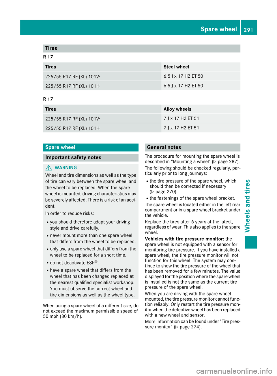
Tires
R17
TiresSteel wheel
225/55R 17RF (XL) 101V,6.5Jx17H2ET5 0
225/55 R17 RF (XL )101H,6.5 Jx17H2ET5 0
R17
TiresAllo ywheels
225/55 R17 RF (XL )101V,7Jx17H2ET5 1
225/55 R17 RF (XL )101H,7Jx17H2ET5 1
Spare wheel
Important safety notes
GWARNING
Wheel and tire dimensions as well as the type of tire can var ybetween the spare whee land
the whee ltobereplaced .Whent he spare
whee lismounted, driving characteristic smay
be severely affected. There is ariskofana cci-
dent.
In order to reduce risks:
Ryo us houl dtherefore adap tyou rd riving
style and drive carefully.
Rneve rmount more thano ne spare wheel
thatd iffer sfrom the whee ltobereplaced.
Ronlyuseaspare whee lthatd iffer sfrom the
whee ltober eplaced for ashort time.
Rdo not deactivate ESP®.
Rhave aspare whee lthatd iffer sfrom the
whee lthath asbeen changed replaced at
the neares tquali fied specialist workshop.
Yo um usto bserve the correct whee land
tire dimensions as well as the whee ltype.
Whe nusing aspare whee lofadifferent size, do
not exceed the maximump ermissibl espeed of
50 mph (80 km/h).
General notes
The procedure for mounting the spare whee lis
describe din"Mounting awheel "(Ypage 287).
The following shoul dbechecked regularly, par-
ticularly prior to long journeys:
Rthe tire pressure of the spare wheel, which
shoul dthen be corrected if necessary
(
Ypage 270).
Rthe fastenings of the spare whee lbracket.
The spare whee lislocate deither in the left rear
compartment or in aspare whee lbracket under
the vehicle.
Replace the tire safter6y ears at the latest,
regardless of wear. Thi salsoa pplies to the spare
wheel.
Vehicles with tire pressure monitor: the
spare whee lisnot equipped with asensor for
monitoring tire pressure. If yo uhavei nstalle da
spare wheel, the tire pressure monitor will not
functio nfor this wheel. The system may con-
tinu etos howt he tire pressure of the whee lthat
hasb eenr emoved for afew minutes. The value
displayed for the position where the spare wheel
is installe disnot the same as the current tire
pressure of the spare wheel.
Whe nyou are driving with the spare wheel
mounted, the tire pressure monitor canno tfunc-
tio nr eliably. Only restart the tire pressure mon-
ito rw henthe defective whee lhas been replaced
with anew whee land sensor.
Mor eInformati on can be found under "Tire pres-
sure
monitor" (Ypage 274).
Spare wheel291
Wheel sand tires
Z
Page 294 of 310
Removingand installing the spare
wheel
Spare wheel undert he rear of the vehi-
cle
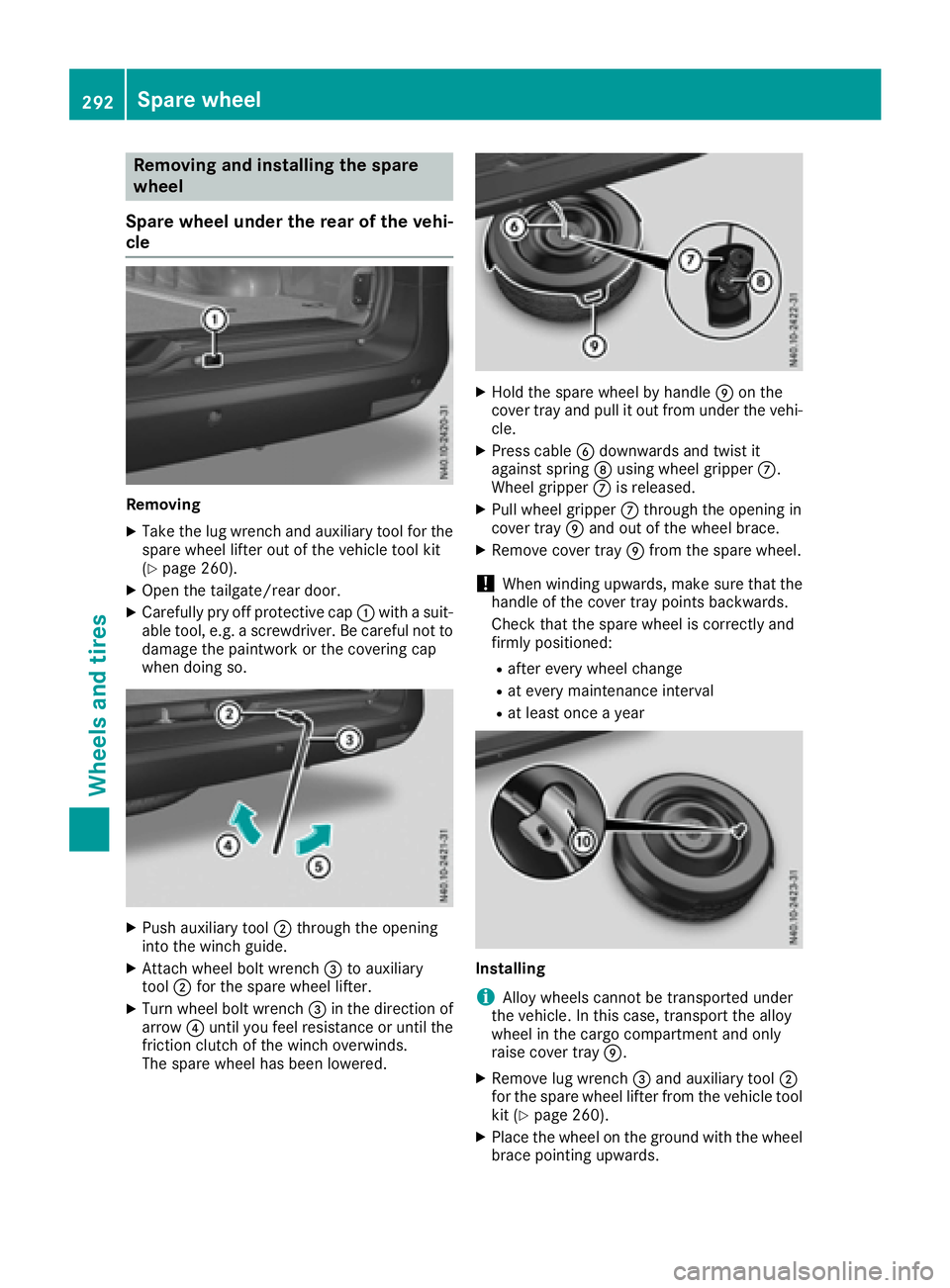
Removing
XTake the lu gwrench and auxiliary tool for the
spare wheel lifter outoft he vehicletool kit
(
Ypage 260).
XOpe nthe tailgate/rea rdoor.
XCarefull ypry off protectiv ecap : with asuit-
able tool ,e.g. ascrewdriver. Be careful not to
damag ethe paintwork or the covering cap
when doing so.
XPush auxiliary tool ;through the opening
into the winch guide.
XAttach wheel bol twrench =to auxiliary
tool ;for the spare wheel lifter.
XTurn wheel bol twrench =in the direction of
arrow ?unti lyou fee lresistance or unti lthe
friction clutch of the winch overwinds.
The spare wheel hasb eenlowered.
XHoldt he spare wheel by handle Eon the
cove rtray and pull it outf rom under the vehi-
cle.
XPress cable Bdownwards and twist it
against spring Dusing wheel gripper C.
Wheel gripper Cis released.
XPull wheel gripper Cthrough the opening in
cove rtray Eand outoft he wheel brace.
XRemove cove rtray Efrom the spare wheel.
!Whe nwinding upwards ,make sure that the
handleoft he covertray points backwards.
Check that the spare wheel is correctly and
firmly positioned:
Rafte revery wheel change
Rat every maintenance interval
Rat leas tonce ayear
Installing
iAlloy wheel scanno tbetransported under
the vehicle. In this case, transpor tthe alloy
wheel in the carg ocompartment and only
raise cove rtray E.
XRemove lu gwrench =and auxiliary tool ;
for the spare wheel lifter from the vehicl etool
kit (
Ypage 260).
XPlace the wheel on the ground with the wheel brace pointing upwards.
292Spare wheel
Wheel sand tires
Page 295 of 310
XPlace cover trayEon the wheel so that the
recess for tire valve Fis above the valve.
XPress cover tray Eont othe wheel brace and
align the wheel so that the handle of cover
tray Efaces backwards.
XGuide wheel gripper Cat an angle on wire B
through the opening in cover tray Eand into
the wheel brace from above.
XSlide the wheel under the vehicle alittle.
XAttach lug wrench =to auxiliary tool ;for
the spare wheel lifter.
XTurn lug wrench =in the direction of arrow
A until you feel resistanc eand the friction
clutch of the winch overwinds in jerks.
The wheel is firmly secured to the underside
of the vehicle.
XPull lug wrench =and auxiliary tool ;for the
spare wheel lifter out of the opening for the
winch.
XClose the winch opening with covering
cap :.
XStow wheel bolt wrench =and auxiliary
tool ;for the spare wheel lifter in the vehicle
tool kit.
XClose the tailgate/rear door.
Sparew heel293
Wheels and tires
Z
Page 300 of 310
The following components of the different vehi-
cle versions influence fuel consumption:
Rtire sizes, tire tread, tire pressure, tire condi-
tion
Rtransmission ratios for the drive assemblies
Radditional equipment (e.g. air-conditioning
system, auxiliary heating system)
For these reasons, the actual consumption fig-
ures for your vehicle may deviate from the con-
sumption figures determined according to EU
Directive 80/1268/EE C.
Detail sonfuelconsumption can be calle dupin
the on-board computer:
Ron vehicles withou tsteerin gwheel buttons
(Ypage 171)
Ron vehicles with steerin gwheel buttons
(Ypage 178)
Engine oil
General notes
When handling engine oil, observe the important
safety note sonserviceproducts (Ypage 295).
The quality of the engine oi lusedisofd ecisive
importance for the engine's functionality and
operating life. Mercedes-Benz continually
approves engine oils based on comple xexperi-
ments according to the current state of the art.
Therefore ,onlyM ercedes-Benz approved
engine oils maybeu sedinM ercedes-Benz
engines. Mercedes-Benz recommends having
the oi lchange dataq ualified specialis twork-
shop. Informatio
nabout approved engine oils can be
obtained:
Rfroma ny Mercedes-Benz Commercial Van
Center
Ron the Internet at
http://bevo.mercedes-benz.co mbyenter ing
th ed esignation ,e.g.2 29.5 .
Mercedes-Ben zapprova lisindicate dont heoil
container by th einscriptio n„MB-Freigabe “or
„MB Approval“ and th ecorre spondin gdesigna-
tion ,e.g.M B-Freig abe or MB Approval 229.5.
Designation softheapprove dengineo ils for
your vehicl e
MB-Freigabe or MB
Approval229.5
Mercedes-Ben zrecommends that you only use
approve dmulti-grade engin eoils of th eSAE
classe sSAE 0W-30 and SA E0W-40 or
SA E5 W-30 and SA E5W-40. These engin eoils
ensur eoptimum lubrication eve natveryl ow
outside temperatures (
Ypage 299).
Whe ntoppin gup, we recommen dthaty ou only
use engin eoil of th esam egrade (MB-Freigabe
or MB Approvaldesignation )and SA Eclass as
th eo il filled at th elast oil change.
iIf th eengineo ils listed in th etable are no t
available, you may add th efollowin gengine
oils until th enexto il change:
RMB-Freigabe or MB Approval 229.1, or
ACE AA3
This mus tonlybea dded once and th eamount
mus tnotbe greate rtha n1q t(1.0l ).
Subsequentl yhavet he engin eoil changed at
th ee arliest possibl eopportunity.
!Using engin eoils of another grade qualit yis
no tp ermitted.
Capacities
!Do no tadd to omucho il. addin gtoo muc h
engin eoil can result in damage to th eengine
or to th ecatalytic converter. Hav eexces s
engin eoil siphoned off .
Oil change includin goil filter
Engin eoilApprox. 2USgal
(7.75 l)
298Service products and capacities
Technical data
Page 305 of 310
Vehicledata
General notes
The following section contains important tech-
nica ldataf or your vehicle. Additionalv ehicle-
specifi cand equipment-dependent technical
data, such as vehicl eweigh ts, can be found in
your vehicl eregistration papers.
Dimensions
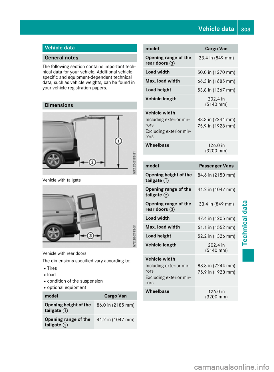
Vehicl ewitht ailgate
Vehicl ewithr eard oors
The dimensions specified var yaccording to:
RTires
Rload
Rcondition of the suspension
Roptional equipment
modelCarg oVan
Opening height of the
tailgate :86.0 in (2185 mm)
Opening rang eofthe
tailgate ;41.2 in (1047 mm)
modelCargoVan
Opening rang eofthe
rear doors =33.4 in (849 mm)
Load width50.0 in (1270 mm)
Max. load width66.3 in (1685 mm)
Load height53.8 in (1367 mm)
Vehiclelengt h202.4 in
(514 0mm)
Vehicl ewidth
Including exterio rmir-
rors
Excluding exterio rmir-
rors
88.3 in (2244 mm)
75.9 in (1928 mm)
Wheelbase126.0 in
(320 0mm)
modelPassenger Vans
Opening height of the
tailgate :84.6 in (2150 mm)
Opening rang eofthe
tailgate ;41.2 in (1047 mm)
Opening rang eofthe
rear doors =33.4 in (849 mm)
Load width47.4 in (1205 mm)
Max. load width61.1 in (1552 mm)
Load height52.2 in (1326 mm)
Vehiclelengt h202.4 in
(514 0mm)
Vehicl ewidth
Including exterio rmir-
rors
Excluding exterio rmir-
rors
88.3 in (2244 mm)
75.9 in (1928 mm)
Wheelbase126.0 in
(320 0mm)
Vehicl edata303
Technica ldata
Z