MERCEDES-BENZ ML SUV 2008 Owners Manual
Manufacturer: MERCEDES-BENZ, Model Year: 2008, Model line: ML SUV, Model: MERCEDES-BENZ ML SUV 2008Pages: 381, PDF Size: 7.18 MB
Page 201 of 381
Loading and stowing
1981
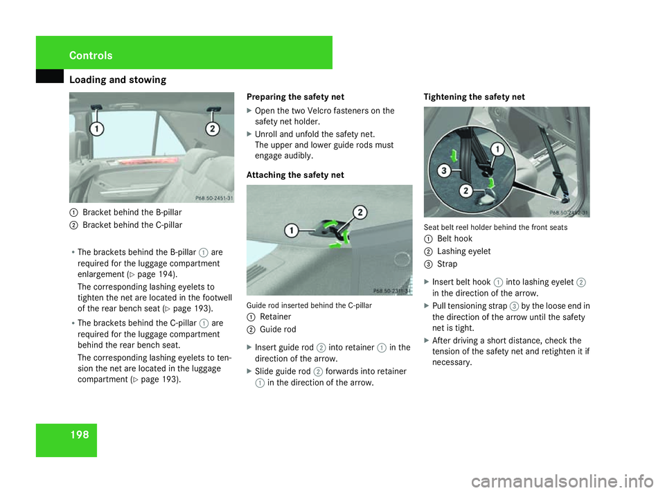
Bracket behind the B-pillar
2 Bracket behind the C-pillar
R The brackets behind the B-pillar 1are
required for the luggage compartment
enlargement (Y page 194).
The corresponding lashing eyelets to
tighten the net are located in the footwell
of the rear bench seat (Y page 193).
R The brackets behind the C-pillar 1are
required for the luggage compartment
behind the rear bench seat.
The corresponding lashing eyelets to ten-
sion the net are located in the luggage
compartment (Y page 193). Preparing the safety net
X
Open the two Velcro fasteners on the
safety net holder.
X Unroll and unfold the safety net.
The upper and lower guide rods must
engage audibly.
Attaching the safety net Guide rod inserted behind the C-pillar
1
Retainer
2 Guide rod
X Insert guide rod 2into retainer 1in the
direction of the arrow.
X Slide guide rod 2forwards into retainer
1 in the direction of the arrow. Tightening the safety net
Seat belt reel holder behind the front seats
1
Belt hook
2 Lashing eyelet
3 Strap
X Insert belt hook 1into lashing eyelet 2
in the direction of the arrow.
X Pull tensioning strap 3by the loose end in
the direction of the arrow until the safety
net is tight.
X After driving a short distance, check the
tension of the safety net and retighten it if
necessary. Controls
164_AKB; 5; 5, en-GB
wobuchh,
Version: 2.10.6 2008-05-11T11:55:12+02:00 - Seite 198Dateiname: 6515_4293_02_buchblock.pdf; preflight
Page 202 of 381
Loading and stowing
199
Releasing the safety net
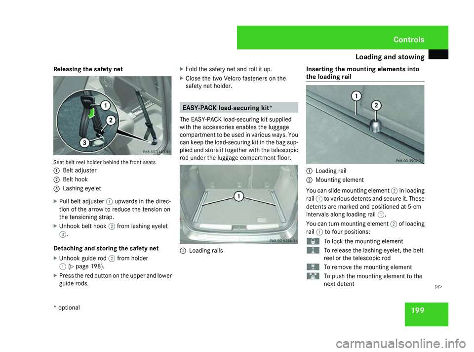
Seat belt reel holder behind the front seats
1
Belt adjuster
2 Belt hook
3 Lashing eyelet
X Pull belt adjuster 1upwards in the direc-
tion of the arrow to reduce the tension on
the tensioning strap.
X Unhook belt hook 2from lashing eyelet
3.
Detaching and storing the safety net
X Unhook guide rod 2from holder
1 (Ypage 198).
X Press the red button on the upper and lower
guide rods. X
Fold the safety net and roll it up.
X Close the two Velcro fasteners on the
safety net holder. EASY-PACK load-securing kit*
The EASY-PACK load-securing kit supplied
with the accessories enables the luggage
compartment to be used in various ways. You
can keep the load-securing kit in the bag sup-
plied and store it together with the telescopic
rod under the luggage compartment floor. 1
Loading rails Inserting the mounting elements into
the loading rail
1
Loading rail
2 Mounting element
You can slide mounting element 2in loading
rail 1to various detents and secure it. These
detents are marked and positioned at 5-cm
intervals along loading rail 1.
You can turn mounting element 2of loading
rail 1to four positions:
‹ To lock the mounting element
N To release the lashing eyelet, the belt
reel or the telescopic rod
L To remove the mounting element
S To push the mounting element to the
next detent Controls
* optional
164_AKB; 5; 5, en-GB
wobuchh,
Version: 2.10.6 2008-05-11T11:55:12+02:00 - Seite 199 ZDateiname: 6515_4293_02_buchblock.pdf; preflight
Page 203 of 381
Loading and stowing
200
X
Turn mounting element 2toL.
X Insert mounting element 2into loading
rail 1.
X Turn mounting element 2to‹ until
you feel it clearly engage in loading rail
1.
Inserting the lashing eyelet into the
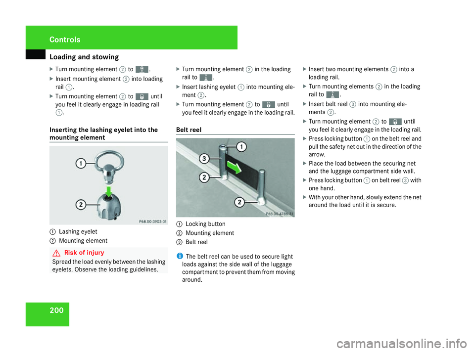
mounting element 1
Lashing eyelet
2 Mounting element G
Risk of injury
Spread the load evenly between the lashing
eyelets. Observe the loading guidelines. X
Turn mounting element 2in the loading
rail to N.
X Insert lashing eyelet 1into mounting ele-
ment 2.
X Turn mounting element 2to‹ until
you feel it clearly engage in the loading rail.
Belt reel 1
Locking button
2 Mounting element
3 Belt reel
i The belt reel can be used to secure light
loads against the side wall of the luggage
compartment to prevent them from moving
around. X
Insert two mounting elements 2into a
loading rail.
X Turn mounting elements 2in the loading
rail to N.
X Insert belt reel 3into mounting ele-
ments 2.
X Turn mounting element 2to‹ until
you feel it clearly engage in the loading rail.
X Press locking button 1on the belt reel and
pull the safety net out in the direction of the
arrow.
X Place the load between the securing net
and the luggage compartment side wall.
X Press locking button 1on belt reel 3with
one hand.
X With your other hand, slowly extend the net
around the load until it is secure. Controls
164_AKB; 5; 5, en-GB
wobuchh,
Version: 2.10.6 2008-05-11T11:55:12+02:00 - Seite 200Dateiname: 6515_4293_02_buchblock.pdf; preflight
Page 204 of 381
Loading and stowing
201
Telescopic rod
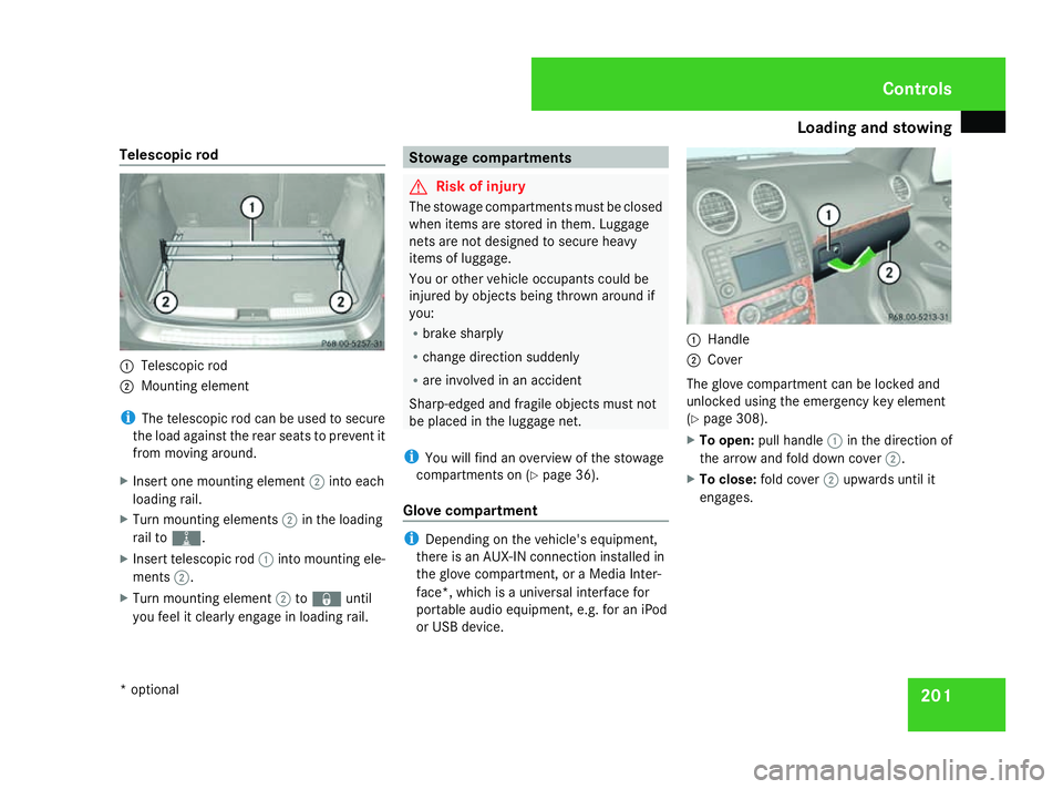
1
Telescopic rod
2 Mounting element
i The telescopic rod can be used to secure
the load against the rear seats to prevent it
from moving around.
X Insert one mounting element 2into each
loading rail.
X Turn mounting elements 2in the loading
rail to N.
X Insert telescopic rod 1into mounting ele-
ments 2.
X Turn mounting element 2to‹ until
you feel it clearly engage in loading rail. Stowage compartments
G
Risk of injury
The stowage compartments must be closed
when items are stored in them. Luggage
nets are not designed to secure heavy
items of luggage.
You or other vehicle occupants could be
injured by objects being thrown around if
you:
R brake sharply
R change direction suddenly
R are involved in an accident
Sharp-edged and fragile objects must not
be placed in the luggage net.
i You will find an overview of the stowage
compartments on (Y page 36).
Glove compartment i
Depending on the vehicle's equipment,
there is an AUX-IN connection installed in
the glove compartment, or a Media Inter-
face*, which is a universal interface for
portable audio equipment, e.g. for an iPod
or USB device. 1
Handle
2 Cover
The glove compartment can be locked and
unlocked using the emergency key element
(Y page 308).
X To open: pull handle 1in the direction of
the arrow and fold down cover 2.
X To close: fold cover 2upwards until it
engages. Controls
* optional
164_AKB; 5; 5, en-GB
wobuchh,
Version: 2.10.6 2008-05-11T11:55:12+02:00 - Seite 201 ZDateiname: 6515_4293_02_buchblock.pdf; preflight
Page 205 of 381
Loading and stowing
202
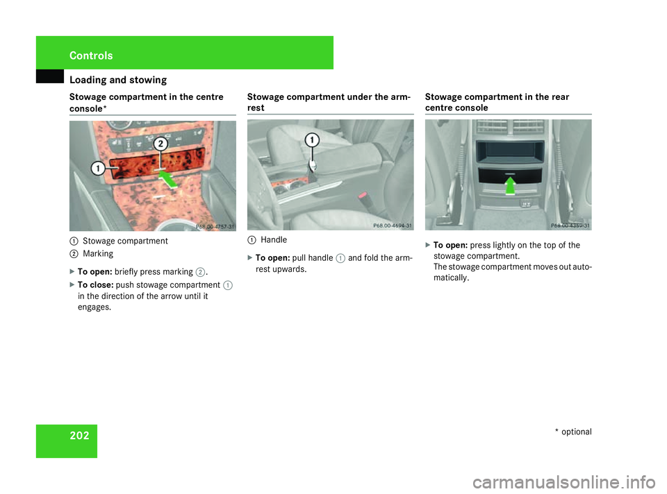
Stowage compartment in the centre
console* 1
Stowage compartment
2 Marking
X To open: briefly press marking 2.
X To close: push stowage compartment 1
in the direction of the arrow until it
engages. Stowage compartment under the arm-
rest 1
Handle
X To open: pull handle 1and fold the arm-
rest upwards. Stowage compartment in the rear
centre console X
To open: press lightly on the top of the
stowage compartment.
The stowage compartment moves out auto-
matically. Controls
* optional
164_AKB; 5; 5, en-GB
wobuchh,
Version: 2.10.6 2008-05-11T11:55:12+02:00 - Seite 202Dateiname: 6515_4293_02_buchblock.pdf; preflight
Page 206 of 381
Features
203Features
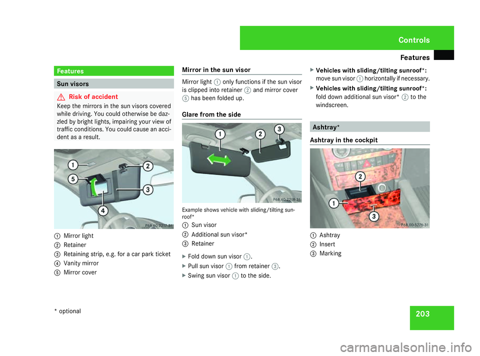
Sun visors
G
Risk of accident
Keep the mirrors in the sun visors covered
while driving. You could otherwise be daz-
zled by bright lights, impairing your view of
traffic conditions. You could cause an acci-
dent as a result. 1
Mirror light
2 Retainer
3 Retaining strip, e.g. for a car park ticket
4 Vanity mirror
5 Mirror cover Mirror in the sun visor Mirror light
1only functions if the sun visor
is clipped into retainer 2and mirror cover
5 has been folded up.
Glare from the side Example shows vehicle with sliding/tilting sun-
roof*
1 Sun visor
2 Additional sun visor*
3 Retainer
X Fold down sun visor 1.
X Pull sun visor 1from retainer 3.
X Swing sun visor 1to the side. X
Vehicles with sliding/tilting sunroof*:
move sun visor 1horizontally if necessary.
X Vehicles with sliding/tilting sunroof*:
fold down additional sun visor* 2to the
windscreen. Ashtray*
Ashtray in the cockpit 1
Ashtray
2 Insert
3 Marking Cont
rols
* optional
164_AKB; 5; 5, en-GB
wobuchh
,V ersion: 2.10.6
2008-05-11T11:55:12+02:00 - Seite 203 ZDateiname: 6515_4293_02_buchblock.pdf; preflight
Page 207 of 381
Features
204
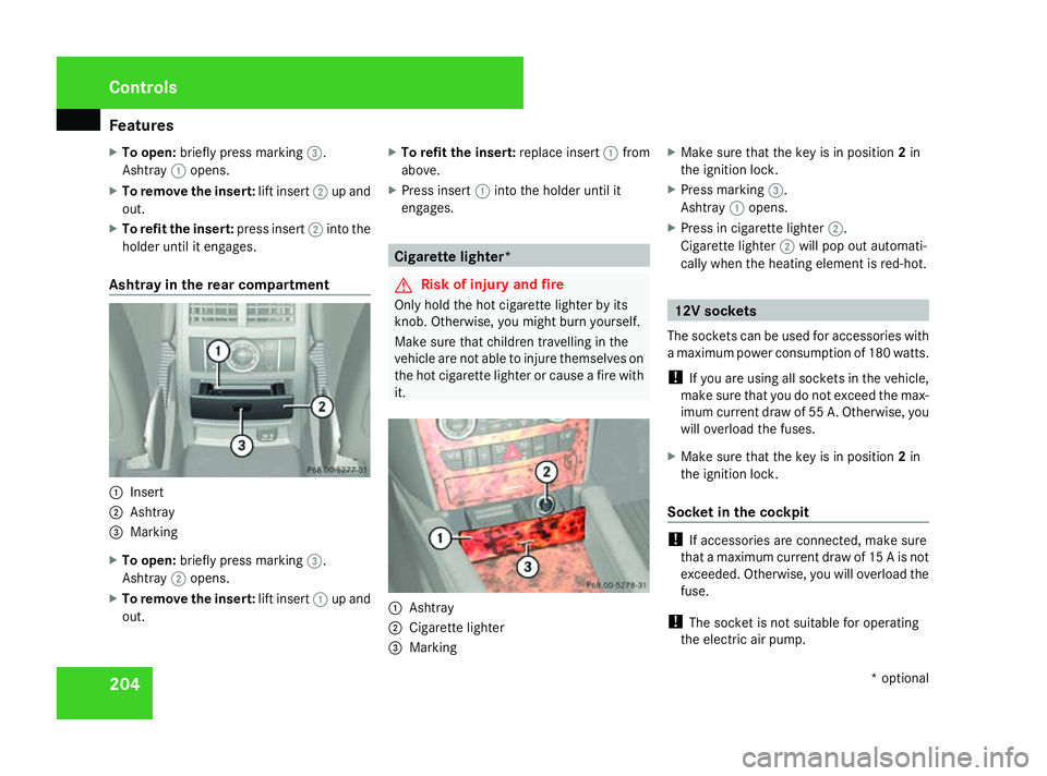
X
To open: briefly press marking 3.
Ashtray 1opens.
X To remove the insert: lift insert2up and
out.
X To refit the insert: press insert2into the
holder until it engages.
Ashtray in the rear compartment 1
Insert
2 Ashtray
3 Marking
X To open: briefly press marking 3.
Ashtray 2opens.
X To remove the insert: lift insert1up and
out. X
To refit the insert: replace insert1from
above.
X Press insert 1into the holder until it
engages. Cigarette lighter*
G
Risk of injury and fire
Only hold the hot cigarette lighter by its
knob. Otherwise, you might burn yourself.
Make sure that children travelling in the
vehicle are not able to injure themselves on
the hot cigarette lighter or cause a fire with
it. 1
Ashtray
2 Cigarette lighter
3 Marking X
Make sure that the key is in position 2in
the ignition lock.
X Press marking 3.
Ashtray 1opens.
X Press in cigarette lighter 2.
Cigarette lighter 2will pop out automati-
cally when the heating element is red-hot. 12V sockets
The sockets can be used for accessories with
a maximum power consumption of 180 watts.
! If you are using all sockets in the vehicle,
make sure that you do not exceed the max-
imum current draw of 55 A. Otherwise, you
will overload the fuses.
X Make sure that the key is in position 2in
the ignition lock.
Socket in the cockpit !
If accessories are connected, make sure
that a maximum current draw of 15 A is not
exceeded. Otherwise, you will overload the
fuse.
! The socket is not suitable for operating
the electric air pump. Cont
rols
* optional
164_AKB; 5; 5, en-GB
wobuchh
,V ersion: 2.10.6
2008-05-11T11:55:12+02:00 - Seite 204 Dateiname: 6515_4293_02_buchblock.pdf; preflight
Page 208 of 381
Features
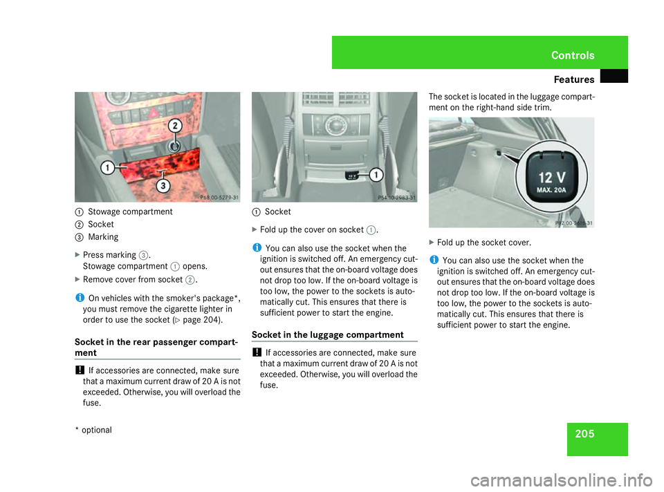
2051
Stowage compartment
2 Socket
3 Marking
X Press marking 3.
Stowage compartment 1opens.
X Remove cover from socket 2.
i On vehicles with the smoker's package*,
you must remove the cigarette lighter in
order to use the socket (Y page 204).
Socket in the rear passenger compart-
ment !
If accessories are connected, make sure
that a maximum current draw of 20 A is not
exceeded. Otherwise, you will overload the
fuse. 1
Socket
X Fold up the cover on socket 1.
i You can also use the socket when the
ignition is switched off. An emergency cut-
out ensures that the on-board voltage does
not drop too low. If the on-board voltage is
too low, the power to the sockets is auto-
matically cut. This ensures that there is
sufficient power to start the engine.
Socket in the luggage compartment !
If accessories are connected, make sure
that a maximum current draw of 20 A is not
exceeded. Otherwise, you will overload the
fuse. The socket is located in the luggage compart-
ment on the right-hand side trim.
X
Fold up the socket cover.
i You can also use the socket when the
ignition is switched off. An emergency cut-
out ensures that the on-board voltage does
not drop too low. If the on-board voltage is
too low, the power to the sockets is auto-
matically cut. This ensures that there is
sufficient power to start the engine. Cont
rols
* optional
164_AKB; 5; 5, en-GB
wobuchh
,V ersion: 2.10.6
2008-05-11T11:55:12+02:00 - Seite 205 ZDateiname: 6515_4293_02_buchblock.pdf; preflight
Page 209 of 381
Features
206 Mobile phone*
G
Risk of accident
Observe the legal requirements of the
country in which you are currently driving
regarding operating mobile communica-
tions equipment in a vehicle.
If it is permitted by law to operate commu-
nications equipment while the vehicle is in
motion, you must only do so when the traf-
fic situation allows. You could otherwise be
distracted from the traffic conditions,
cause an accident and injure yourself and
others.
Two-way radios and fax equipment used
without low-reflection exterior aerials can
interfere with the vehicle's electronics and
thereby jeopardise the operating safety of
the vehicle and your safety. You must there-
fore only use this equipment if it is correctly
connected to a separate reflection-free
exterior aerial. G
Risk of injury
Excessive electromagnetic radiation may
cause damage to your health and the health
of others. Using an exterior aerial takes into
account current scientific discussions relating to the possible health risk posed by
electromagnetic fields.
i In order to ensure optimum signal quality
for mobile phones and to minimise mutual
interference between the vehicle electron-
ics and mobile phones, Mercedes-Benz rec-
ommends the use of an approved exterior
aerial. An exterior aerial conducts the elec-
tromagnetic fields generated by a wireless
device to the exterior of the vehicle; the
field strength within the vehicle interior is
lower than in a vehicle that does not have
an exterior aerial.
i There are various mobile phone brackets
that may be fitted to your vehicle; in some
cases these are country-specific. You can
obtain these mobile phone brackets from a
qualified specialist workshop, e.g. a
Mercedes-Benz Service Centre. The func-
tions and services available when you use
the phone depend on your mobile phone
model and service provider.
The mobile phone bracket is in the armrest.
X Open the telephone compartment
(Y page 202). Inserting the mobile phone into the
mobile phone bracket If the mobile phone is inserted into the mobile
phone bracket, you can only speak to the per-
son you are calling using the hands-free sys-
tem.
!
Do not attempt to remove the mobile
phone and the telephone bracket together.
You could otherwise damage the mobile
phone bracket.
X Remove the cover of the aerial plug from
the back of the mobile phone and keep it in
a safe place. Cont
rols
* optional
164_AKB; 5; 5, en-GB
wobuchh
,V ersion: 2.10.6
2008-05-11T11:55:12+02:00 - Seite 206 Dateiname: 6515_4293_02_buchblock.pdf; preflight
Page 210 of 381
Features
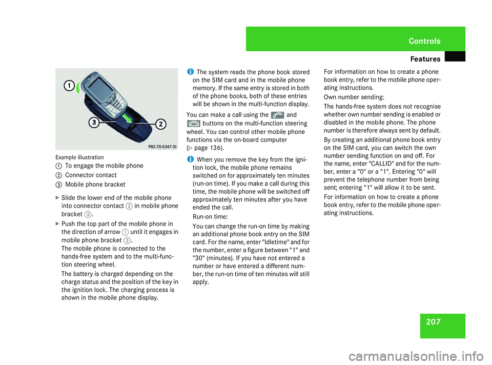
207Example illustration
1
To engage the mobile phone
2 Connector contact
3 Mobile phone bracket
X Slide the lower end of the mobile phone
into connector contact 2in mobile phone
bracket 3.
X Push the top part of the mobile phone in
the direction of arrow 1until it engages in
mobile phone bracket 3.
The mobile phone is connected to the
hands-free system and to the multi-func-
tion steering wheel.
The battery is charged depending on the
charge status and the position of the key in
the ignition lock. The charging process is
shown in the mobile phone display. i
The system reads the phone book stored
on the SIM card and in the mobile phone
memory. If the same entry is stored in both
of the phone books, both of these entries
will be shown in the multi-function display.
You can make a call using the sand
t buttons on the multi-function steering
wheel. You can control other mobile phone
functions via the on-board computer
(Y page 136).
i When you remove the key from the igni-
tion lock, the mobile phone remains
switched on for approximately ten minutes
(run-on time). If you make a call during this
time, the mobile phone will be switched off
approximately ten minutes after you have
ended the call.
Run-on time:
You can change the run-on time by making
an additional phone book entry on the SIM
card. For the name, enter "Idletime" and for
the number, enter a figure between "1" and
"30" (minutes). If you have not entered a
number or have entered a different num-
ber, the run-on time of ten minutes will still
apply. For information on how to create a phone
book entry, refer to the mobile phone oper-
ating instructions.
Own number sending:
The hands-free system does not recognise
whether own number sending is enabled or
disabled in the mobile phone. The phone
number is therefore always sent by default.
By creating an additional phone book entry
on the SIM card, you can switch the own
number sending function on and off. For
the name, enter "CALLID" and for the num-
ber, enter a "0" or a "1". Entering "0" will
prevent the telephone number from being
sent; entering "1" will allow it to be sent.
For information on how to create a phone
book entry, refer to the mobile phone oper-
ating instructions. Controls
164_AKB; 5; 5, en-GB
wobuchh,
Version: 2.10.6
2008-05-11T11:55:12+02:00 - Seite 207 ZDateiname: 6515_4293_02_buchblock.pdf; preflight