engine MERCEDES-BENZ ML320 2002 W163 Owner's Manual
[x] Cancel search | Manufacturer: MERCEDES-BENZ, Model Year: 2002, Model line: ML320, Model: MERCEDES-BENZ ML320 2002 W163Pages: 342, PDF Size: 13.75 MB
Page 278 of 342
275 Jump starting
Te ch n i c a l
data Instruments
and controlsOperation DrivingInstrument
cluster displayPractical hintsCar care Index Jump startingImportant!
A discharged battery can freeze at approximately +14
°F
(–10
°C). In that case, it must be thawed out before
jumper cables are used. Attempting to jump start a
frozen battery can result in it exploding, causing
personal injury.
Jumper cable specifications:
•Minimum cable cross-section of 25 mm
2 or
approximately 2 AWG
•Maximum length of 11.5 ft. (3.5 m).
If the battery is discharged, the engine should be started
with jumper cables and the (12 V) battery of another
vehicle.
Only use 12 V battery to jump start your vehicle. Jump
starting with more powerful battery could damage the
vehicle’s electrical systems, which will not be covered
by the Mercedes-Benz Limited Warranty.
Wa r n i n g !
Failure to follow these directions will cause
damage to the electronic components, and can lead
to a battery explosion and severe injury or death.Never lean over batteries while connecting or jump
starting, you might get injured.Battery fluid contains sulfuric acid. Do not allow
this fluid to come in contact with eyes, skin or
clothing. In case it does, immediately flush affected
area with water, and seek medical help if
necessary.A battery will also produce hydrogen gas, which is
flammable and very explosive. Keep flames or
sparks away from battery, avoid improper
connection of jumper cables, smoking etc..Read all instructions before proceeding.
Page 279 of 342
276 Jump starting
Te ch n i c a l
data Instruments
and controlsOperation DrivingInstrument
cluster displayPractical hintsCar care Index
The battery is located on the right side in the engine
compartment.
Proceed as follows:
1. Position the vehicle with the charged battery so that
the jumper cables will reach, but never let the
vehicles touch. Make sure the jumper cables do not
have loose or missing insulation.
2. On both vehicles:
•Turn off engine and all lights and accessories,
except hazard warning flashers or work lights.
•Apply parking brake and shift selector lever to
position “P”.
Important!
3. Clamp one end of the first jumper cable to the
positive (+) under hood terminal of the discharged
battery and the other end to the positive (+) terminal
of the charged battery. Make sure the cable clamps
do not touch any other metal parts.
4. Clamp one end of the second jumper cable to the
grounded negative (–) terminal of the charged
battery and the final connection to the negative (–)
terminal of the discharged battery.Important!
5. Start engine of the vehicle with the charged battery
and run at high idle. Make sure the cables are not
on or near pulleys, fans, or other parts that move
when the engine is started. Allow the discharged
battery to charge for a few minutes. Start engine of
the disabled vehicle in the usual manner.
6. After the engine has started, remove jumper cables
by exactly reversing the above installation
sequence, starting with the last connection made
first. When removing each clamp, make sure that it
does not touch any other metal while the other end
is still attached.
Notes:
If engine does not run after several unsuccessful
starting attempts, have it checked at the nearest
authorized Mercedes-Benz Light Truck Center.
Excessive unburned fuel may damage the catalytic
converter.
Page 280 of 342
277 Towing
Te ch n i c a l
data Instruments
and controlsOperation DrivingInstrument
cluster displayPractical hintsCar care Index Towing the vehicle
Important!
When towing the vehicle, please, note the following:
With the automatic central locking activated and the
engine running, the vehicle doors lock if the left front
wheel is turning at vehicle speeds of approximately
9 mph (15 km / h) or more.
To prevent the vehicle door locks from locking,
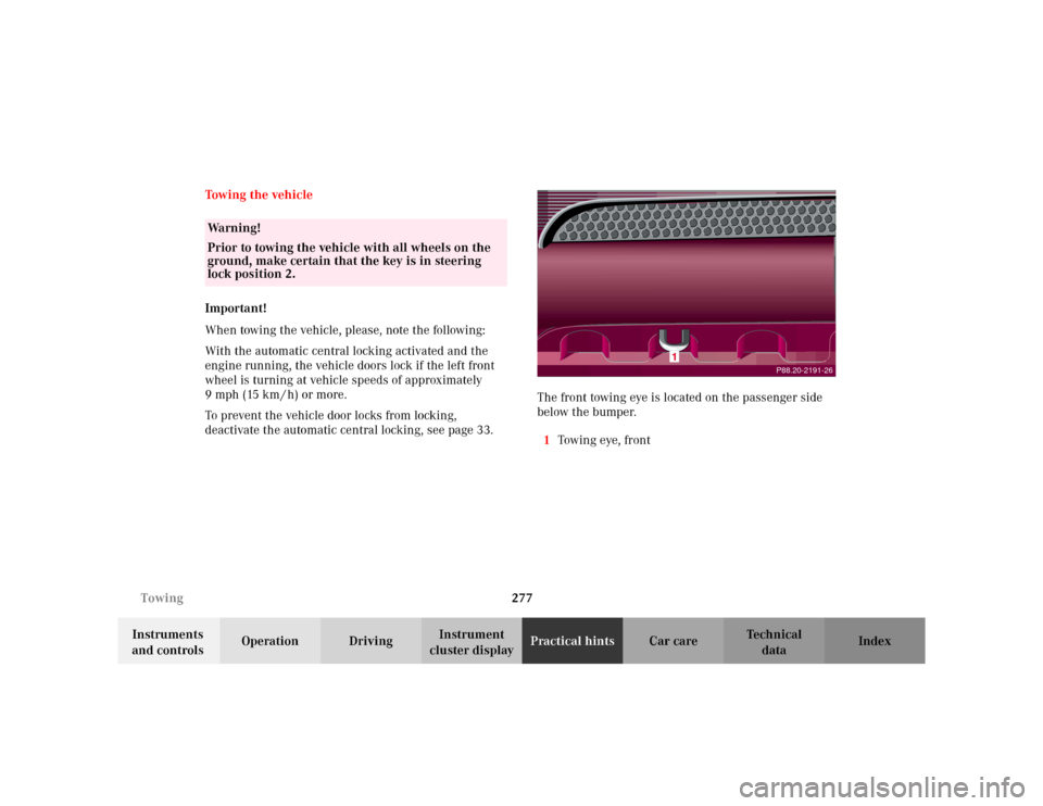
deactivate the automatic central locking, see page 33.The front towing eye is located on the passenger side
below the bumper.
1Towin g eye, fr on t
Wa r n i n g !
Prior to towing the vehicle with all wheels on the
ground, make certain that the key is in steering
lock position 2.
P88.20-2191-26
Page 283 of 342
280 Towing
Te ch n i c a l
data Instruments
and controlsOperation DrivingInstrument
cluster displayPractical hintsCar care Index
To be certain to avoid additional damage to the vehicle
powertrain, however you should do the following:
•With damage to front axle, raise front axle. Remove
flexible drive shaft between rear axle and transfer
case
•With damage to rear axle, raise rear axle and tow
vehicle with wheel lift or dolly placed under front
wheels.
•With damage to transfer case, remove flexible drive
shafts to the drive axles.
Note:
Always install new self-locking nuts when reinstalling
the flexible drive shaft.Caution!
If the vehicle is towed with the front axle raised, the
engine must be shut off (key in steering lock position 1).
Otherwise, the 4-ETS+ may become engaged which may
cause loss of towing control. Switch off the tow-away
alarm (see page 37) as well as the ESP (see page 225).
Note:
To signal turns while being towed with hazard warning
flasher in use, turn key in steering lock to position 2
and activate combination switch for left or right turn
signal in usual manner. Now deactivate the hazard
warning flasher, only the selected turn signal will
operate. Upon canceling the turn signal, the hazard
warning flasher must be activated again.
Wa r n i n g !
With the engine not running, there is no power
assistance for the braking and steering systems. In
this case, it is important to keep in mind that a
considerably higher degree of effort is necessary to
brake and steer the vehicle.
Page 298 of 342
295 Manual release for fuel filler flap
Te ch n i c a l
data Instruments
and controlsOperation DrivingInstrument
cluster displayPractical hintsCar care Index Manual release for fuel filler flap
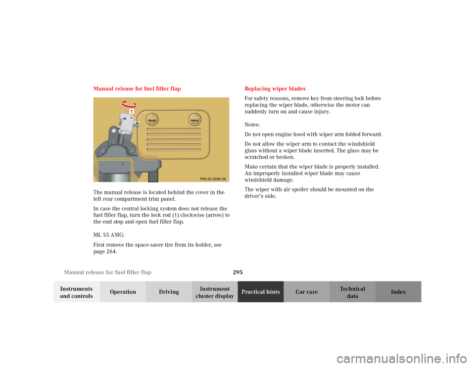
The manual release is located behind the cover in the
left rear compartment trim panel.
In case the central locking system does not release the
fuel filler flap, turn the lock rod (1) clockwise (arrow) to
the end stop and open fuel filler flap.
ML 55 AMG:
First remove the space-saver tire from its holder, see
page 264.Replacing wiper blades
For safety reasons, remove key from steering lock before
replacing the wiper blade, otherwise the motor can
suddenly turn on and cause injury.
Notes:
Do not open engine hood with wiper arm folded forward.
Do not allow the wiper arm to contact the windshield
glass without a wiper blade inserted. The glass may be
scratched or broken.
Make certain that the wiper blade is properly installed.
An improperly installed wiper blade may cause
windshield damage.
The wiper with air spoiler should be mounted on the
driver’s side.
1
P80.20-2296-26
Page 300 of 342
297 Contents - Car care
Te ch n i c a l
data Instruments
and controlsOperation DrivingInstrument
cluster displayPractical hintsCar careIndex
Vehicle careCleaning and care of the vehicle .298
Power washer ..............................299
Tar stains .....................................299
Paintwork, painted body
components .................................299
Engine cleaning ..........................300
Vehicle washing .........................300
Ornamental moldings ................300
Headlamps, taillamps,
turn signal lenses ......................300
Cleaning the parktronic
system sensors ........................... 301Window cleaning ....................... 301
Wiper blades .............................. 301
Light alloy wheels ..................... 302
Instrument cluster ..................... 302
Steering wheel and
gear selector lever ..................... 302
Cup holder .................................. 302
Seat belts ..................................... 302
Headliner .................................... 302
Upholstery .................................. 303
Hard plastic trim items ............. 303
Plastic and rubber parts ........... 303
Page 303 of 342
300 Cleaning and care of the vehicle
Te ch n i c a l
data Instruments
and controlsOperation DrivingInstrument
cluster displayPractical hintsCar careIndex
Engine cleaning
Prior to cleaning the engine compartment make sure to
protect electrical components and connectors from the
intrusion of water and cleaning agents.
Corrosion protection, such as MB Anticorrosion Wax
should be applied to the engine compartment after
every engine cleaning. Before applying, all control
linkage bushings and joints should be lubricated. The
poly-V-belt and all pulleys should be protected from any
wax.
Vehicle washing
Do not use hot water or wash your vehicle in direct
sunlight. Use only a mild car wash detergent, such as
Mercedes-Benz approved Car Shampoo.
Thoroughly spray the vehicle with a diffused jet of
water. Direct only a very weak spray towards the
ventilation intake. Use plenty of water and rinse the
sponge and chamois frequently.
Rinse with clear water and thoroughly wipe dry with a
chamois. Do not allow cleaning agents to dry on the
finish.Due to the width of the vehicle, prior to running the
vehicle through an automatic car wash, fold back the
outside mirrors to prevent them from getting damaged.
In the winter, thoroughly remove all traces of road salt
as soon as possible.
When washing the underbody, do not forget to clean the
inner sides of the wheels.
Ornamental moldings
For regular cleaning and care of very dirty chrome-
plated parts, use a chrome cleaner.
Headlamps, taillamps, turn signal lenses
Use a mild car wash detergent, such as Mercedes-Benz
approved Car Shampoo, with plenty of water.
To prevent scratches, never apply strong force and use
only a soft, non-scratchy cloth when cleaning the lenses.
Do not attempt to wipe dirty lenses with a dry cloth or
sponge.
Page 308 of 342
305 Contents - Technical data
Te ch n i c a l
data Instruments
and controlsOperation DrivingInstrument
cluster displayPractical hints Car care Index
Technical dataSpare parts service ........................306
Warranty coverage .........................306
Identification labels .......................307
Layout of poly-V-belt drive ............308
Technical data ................................309
Fuels, coolants, lubricants etc. –
capacities ................................... 314Engine oils ....................................... 316
Engine oil additives ....................... 316
Air conditioner refrigerant ........... 316
Brake fluid ....................................... 316
Premium unleaded gasoline ......... 317
Fuel requirements ......................... 317
Gasoline additives .......................... 318
Coolants ........................................... 318
Consumer information ................. 320
Page 310 of 342
307 Technical data
Te ch n i c a l
data Instruments
and controlsOperation DrivingInstrument
cluster displayPractical hints Car care Index Identification labels
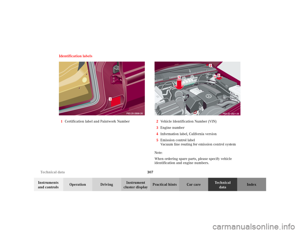
1Certification label and Paintwork Number2Vehicle Identification Number (VIN)
3Engine number
4Information label, California version
5Emission control label
Vacuum line routing for emission control system
Note:
When ordering spare parts, please specify vehicle
identification and engine numbers.
Page 312 of 342
309 Technical data
Te ch n i c a l
data Instruments
and controlsOperation DrivingInstrument
cluster displayPractical hints Car care Index Te ch n i c a l d a t a
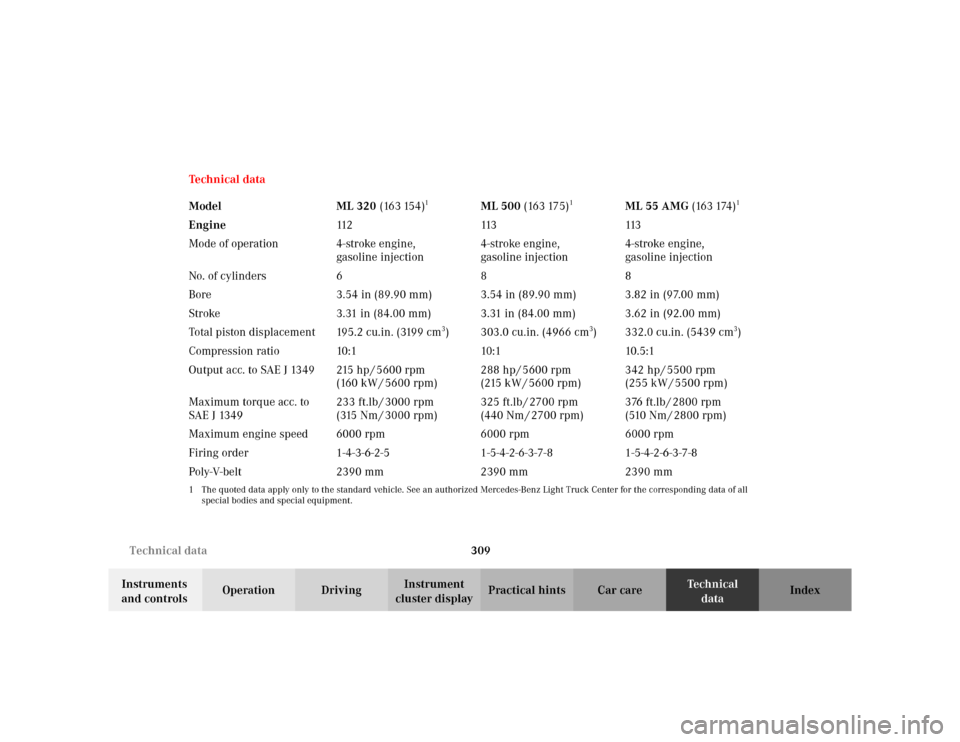
Model ML 320 (163 154)
1
ML 500 (163 175)
1
ML 55 AMG (163 174)
1
Engine11 2 113 113
Mode of operation 4-stroke engine,
gasoline injection4-stroke engine,
gasoline injection4-stroke engine,
gasoline injection
No. of cylinders 6 8 8
Bore 3.54 in (89.90 mm) 3.54 in (89.90 mm) 3.82 in (97.00 mm)
Stroke 3.31 in (84.00 mm) 3.31 in (84.00 mm) 3.62 in (92.00 mm)
Total piston displacement 195.2 cu.in. (3199 cm
3) 303.0 cu.in. (4966 cm
3) 332.0 cu.in. (5439 cm
3)
Compression ratio 10:1 10:1 10.5:1
Output acc. to SAE J 1349 215 hp / 5600 rpm
(160 kW / 5600 rpm)288 hp / 5600 rpm
(215 kW / 5600 rpm)342 hp / 5500 rpm
(255 kW / 5500 rpm)
Maximum torque acc. to
SAE J 1349233 ft.lb / 3000 rpm
(315 Nm / 3000 rpm)325 ft.lb / 2700 rpm
(440 Nm / 2700 rpm)376 ft.lb / 2800 rpm
(510 Nm / 2800 rpm)
Maximum engine speed 6000 rpm 6000 rpm 6000 rpm
Firing order 1-4-3-6-2-5 1-5-4-2-6-3-7-8 1-5-4-2-6-3-7-8
Poly-V-belt 2390 mm 2390 mm 2390 mm
1 The quoted data apply only to the standard vehicle. See an authorized Mercedes-Benz Light Truck Center for the corresponding data of all
special bodies and special equipment.