MERCEDES-BENZ ML430 1997 Complete Repair Manual
Manufacturer: MERCEDES-BENZ, Model Year: 1997, Model line: ML430, Model: MERCEDES-BENZ ML430 1997Pages: 4133, PDF Size: 88.89 MB
Page 1811 of 4133
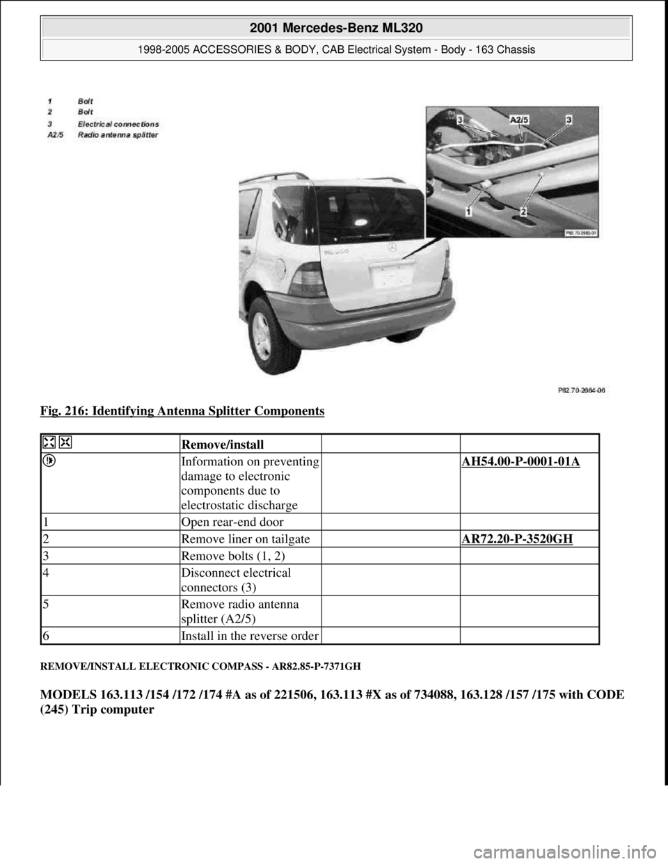
Fig. 216: Identifying Antenna Splitter Components
REMOVE/INSTALL ELECTRONIC COMPASS - AR82.85-P-7371GH
MODELS 163.113 /154 /172 /174 #A as of 221506, 163.113 #X as of 734088, 163.128 /157 /175 with CODE
(245) Trip computer
Remove/install
Information on preventing
damage to electronic
components due to
electrostatic discharge AH54.00-P-0001-01A
1Open rear-end door
2Remove liner on tailgate AR72.20-P-3520GH
3Remove bolts (1, 2)
4Disconnect electrical
connectors (3)
5Remove radio antenna
splitter (A2/5)
6Install in the reverse order
2001 Mercedes-Benz ML320
1998-2005 ACCESSORIES & BODY, CAB Electrical System - Body - 163 Chassis
me
Saturday, October 02, 2010 3:30:10 PMPage 316 © 2006 Mitchell Repair Information Company, LLC.
Page 1812 of 4133
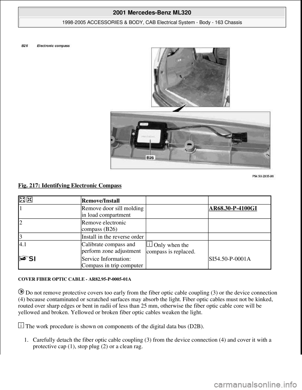
Fig. 217: Identifying Electronic Compass
COVER FIBER OPTIC CABLE - AR82.95-P-0005-01A
Do not remove protective covers too early from the fiber optic cable coupling (3) or the device connection
(4) because contaminated or scratched surfaces may absorb the light. Fiber optic cables must not be kinked,
routed over sharp edges or bent in radii of less than 25 mm, otherwise the fiber optic cable core will be
yellowed and broken. Yellowed or broken fiber optic cables weaken the light.
The work procedure is shown on components of the digital data bus (D2B).
1. Carefully detach the fiber optic cable coupling (3) from the device connection (4) and cover it with a
protective cap (1), stop plug (2) or a clean rag.
Remove/Install
1Remove door sill molding
in load compartment AR68.30-P-4100GI
2Remove electronic
compass (B26)
3Install in the reverse order
4.1Calibrate compass and
perform zone adjustment Only when the
compass is replaced.
Service Information:
Compass in trip computer SI54.50-P-0001A
2001 Mercedes-Benz ML320
1998-2005 ACCESSORIES & BODY, CAB Electrical System - Body - 163 Chassis
me
Saturday, October 02, 2010 3:30:10 PMPage 317 © 2006 Mitchell Repair Information Company, LLC.
Page 1813 of 4133
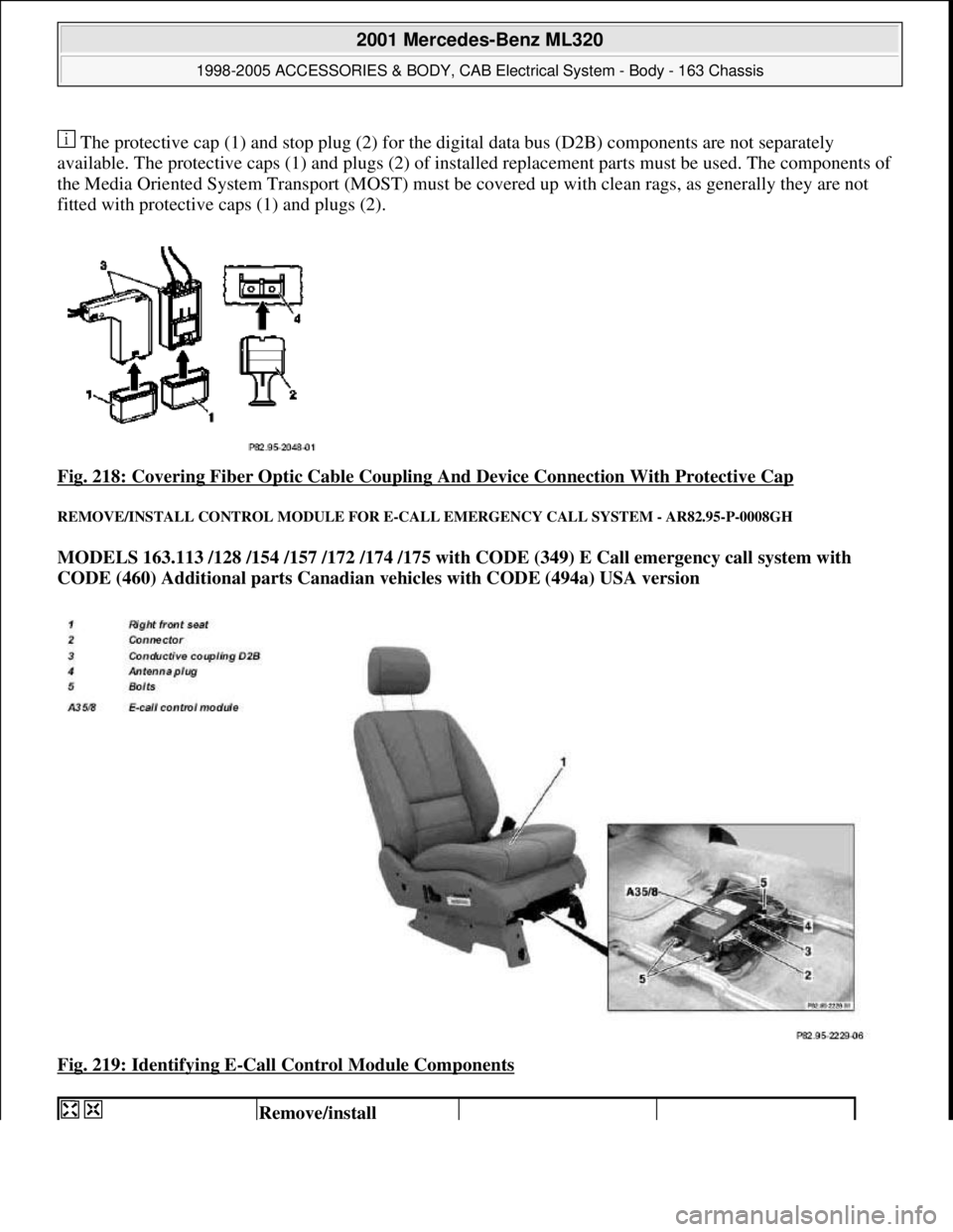
The protective cap (1) and stop pl ug (2) for the digital data bus (D2B) components are not separately
available. The protective caps (1) a nd plugs (2) of installed replacement pa rts must be used. The components of
the Media Oriented System Transport (MOST) must be covered up with clean rags, as generally they are not
fitted with protective caps (1) and plugs (2).
Fig. 218: Covering Fiber Optic Cable Coupling And Device Connection With Protective Cap
REMOVE/INSTALL CONTROL MODULE FOR E-CALL EMERGENCY CALL SYSTEM - AR82.95-P-0008GH
MODELS 163.113 /128 /154 /157 /172 /174 /175 with CODE (349) E Call emergency call system with
CODE (460) Additional parts Canadian vehicles with CODE (494a) USA version
Fig. 219: Identifying E
-Call Control Module Components
Remove/install
2001 Mercedes-Benz ML320
1998-2005 ACCESSORIES & BODY, CAB Electr ical System - Body - 163 Chassis
me
Saturday, October 02, 2010 3:30:10 PMPage 318 © 2006 Mitchell Repair Information Company, LLC.
Page 1814 of 4133
![MERCEDES-BENZ ML430 1997 Complete Repair Manual Front seats
REPLACE FIBER OPTICAL CABLE (D2B) BETWEEN THE RADIO AND E-CALL CONTROL MODULE/CTEL [TEL]
INTERFACE (AFTER TESTING) - AR82.95-P-0015GH
MODEL 163.136 #A as of 051500, 163.136 #X as of 70 MERCEDES-BENZ ML430 1997 Complete Repair Manual Front seats
REPLACE FIBER OPTICAL CABLE (D2B) BETWEEN THE RADIO AND E-CALL CONTROL MODULE/CTEL [TEL]
INTERFACE (AFTER TESTING) - AR82.95-P-0015GH
MODEL 163.136 #A as of 051500, 163.136 #X as of 70](/img/4/57307/w960_57307-1813.png)
Front seats
REPLACE FIBER OPTICAL CABLE (D2B) BETWEEN THE RADIO AND E-CALL CONTROL MODULE/CTEL [TEL]
INTERFACE (AFTER TESTING) - AR82.95-P-0015GH
MODEL 163.136 #A as of 051500, 163.136 #X as of 708319, 163.154 #A as of 051500, 163.154 #X as of
708319, 163.172 #A as of 051500, 163.172 #X as of 708319, 163.113/128/157/174/175 with CODE (852)
CTEL preinstallation assembly at dome with CODE (854) MB portable cellular telephone
MODEL 163.154 /172 /174 #A as of 221506, 163.157/175 with CODE (349) E Call emergency call system
with CODE (494a) USA version
1Remove fuse f8 from fuse
and relay module
2Unscrew screws on front
seat console *BA91.10-P-1001-01B
3Angle front seat back
until it rests against the
rear bench seat and fasten
with outer seat belt Remove wiring
harness for E-call speaker
from E-call bracket.
Cover the floor covering
behind the front seat to
avoid contamination.
4Detach connector (2) and
antenna plug (4) from the
E-call control module
(A35/8)
5Detach conductive
coupling D2B (3) Do not kink or stretch
fiber optic cable. Press
protective caps on
conductive coupling and
device connection.AR82.95-P-0005-01A
6Unscrew screws (5)
7Remove E-call control
module (A35/8)
8Install in the reverse order
NumberDesignationModel Series 163
BA91.10-P-1001-01BBolt of seating mounting
bracket to vehicle floorNm40
2001 Mercedes-Benz ML320
1998-2005 ACCESSORIES & BODY, CAB Electrical System - Body - 163 Chassis
me
Saturday, October 02, 2010 3:30:10 PMPage 319 © 2006 Mitchell Repair Information Company, LLC.
Page 1815 of 4133
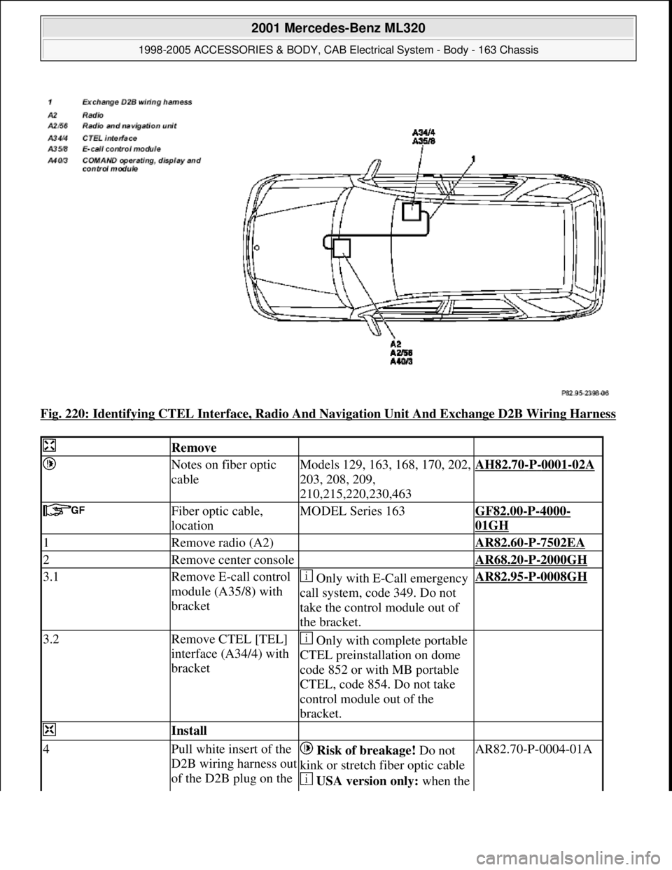
Fig. 220: Identifying CTEL Interface, Radio And Navigation Unit And Exchange D2B Wiring Harness
Remove
Notes on fiber optic
cableModels 129, 163, 168, 170, 202,
203, 208, 209,
210,215,220,230,463AH82.70-P-0001-02A
Fiber optic cable,
locationMODEL Series 163GF82.00-P-4000-
01GH
1Remove radio (A2) AR82.60-P-7502EA
2Remove center console AR68.20-P-2000GH
3.1Remove E-call control
module (A35/8) with
bracket Only with E-Call emergency
call system, code 349. Do not
take the control module out of
the bracket.AR82.95-P-0008GH
3.2Remove CTEL [TEL]
interface (A34/4) with
bracket Only with complete portable
CTEL preinstallation on dome
code 852 or with MB portable
CTEL, code 854. Do not take
control module out of the
bracket.
Install
4Pull white insert of the
D2B wiring harness out
of the D2B plug on the Risk of breakage! Do not
kink or stretch fiber optic cable
USA version only: when the AR82.70-P-0004-01A
2001 Mercedes-Benz ML320
1998-2005 ACCESSORIES & BODY, CAB Electrical System - Body - 163 Chassis
me
Saturday, October 02, 2010 3:30:10 PMPage 320 © 2006 Mitchell Repair Information Company, LLC.
Page 1816 of 4133
![MERCEDES-BENZ ML430 1997 Complete Repair Manual E-call control module/
CTEL [TEL] interface
and replace with the
white insert of the
exchange D2B wiring
harnessvoice control system (SBS) is
installed, the white D2B insert
should be removed f MERCEDES-BENZ ML430 1997 Complete Repair Manual E-call control module/
CTEL [TEL] interface
and replace with the
white insert of the
exchange D2B wiring
harnessvoice control system (SBS) is
installed, the white D2B insert
should be removed f](/img/4/57307/w960_57307-1815.png)
E-call control module/
CTEL [TEL] interface
and replace with the
white insert of the
exchange D2B wiring
harnessvoice control system (SBS) is
installed, the white D2B insert
should be removed from the
voice control system control
module and not from the E-call
control module/CTEL [TEL]
interface.
Pay attention to the correct
installation position of the insert
in the D2B plug. Cut off the
fiber optical cable removed at
the adhesive tape.
5Route exchange D2B
wiring harness (1)
under the floor
covering to the
transmission tunnel
6Route exchange D2B
wiring harness (1) at
the top of the
transmission tunnel to
the center part of the
instrument panel Route fiber optical cable
under the air duct. Guide it past
all components on the left side.
7Route exchange D2B
wiring harness (1)
behind the instrument
panel to the radio
installation opening
8Remove red insert of
the D2B wiring harness
from the D2B plug on
the radio and replace
with the red insert of
the exchange D2B
wiring harness Risk of breakage! Do not
kink or stretch fiber optic cable
Pay attention to the correct
installation position of the insert
in the D2 B-plug. Cut off the
fiber optical cable removed at
the adhesive tape.AR82.70-P-0004-01A
9Fasten exchange D2B
wiring harness (1) to
the existing D2B
wiring harness of the
radio
10.1Install CTEL [TEL]
interface (A34/4) with
bracket Only with complete portable
CTEL-preinstallation on dome,
code 852 or with MB portable
CTEL, code 854.
*BA91.10-P-1001-01B
*BA91.40-P-1001-01D
2001 Mercedes-Benz ML320
1998-2005 ACCESSORIES & BODY, CAB Electrical System - Body - 163 Chassis
me
Saturday, October 02, 2010 3:30:10 PMPage 321 © 2006 Mitchell Repair Information Company, LLC.
Page 1817 of 4133
Front seats
Seat belts/emergency tensioning retractors
MAINTENANCE
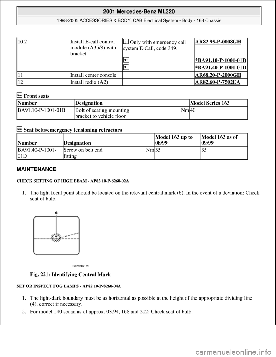
CHECK SETTING OF HIGH BEAM - AP82.10-P-8260-02A
1. The light focal point should be located on the relevant central mark (6). In the event of a deviation: Check
seat of bulb.
Fig. 221: Identifying Central Mark
SET OR INSPECT FOG LAMPS - AP82.10-P-8260-04A
1. The light-dark boundary must be as horizontal as possible at the height of the appropriate dividing line
(4), correct if necessary.
2. For model 140 sedan as of approx. 03.94, 168 and 202: Check seat of bulb.
10.2Install E-call control
module (A35/8) with
bracket Only with emergency call
system E-Call, code 349.AR82.95-P-0008GH
*BA91.10-P-1001-01B
*BA91.40-P-1001-01D
11Install center console AR68.20-P-2000GH
12Install radio (A2) AR82.60-P-7502EA
NumberDesignationModel Series 163
BA91.10-P-1001-01BBolt of seating mounting
bracket to vehicle floorNm40
NumberDesignation
Model 163 up to
08/99Model 163 as of
09/99
BA91.40-P-1001-
01DScrew on belt end
fittingNm3535
2001 Mercedes-Benz ML320
1998-2005 ACCESSORIES & BODY, CAB Electrical System - Body - 163 Chassis
me
Saturday, October 02, 2010 3:30:10 PMPage 322 © 2006 Mitchell Repair Information Company, LLC.
Page 1818 of 4133
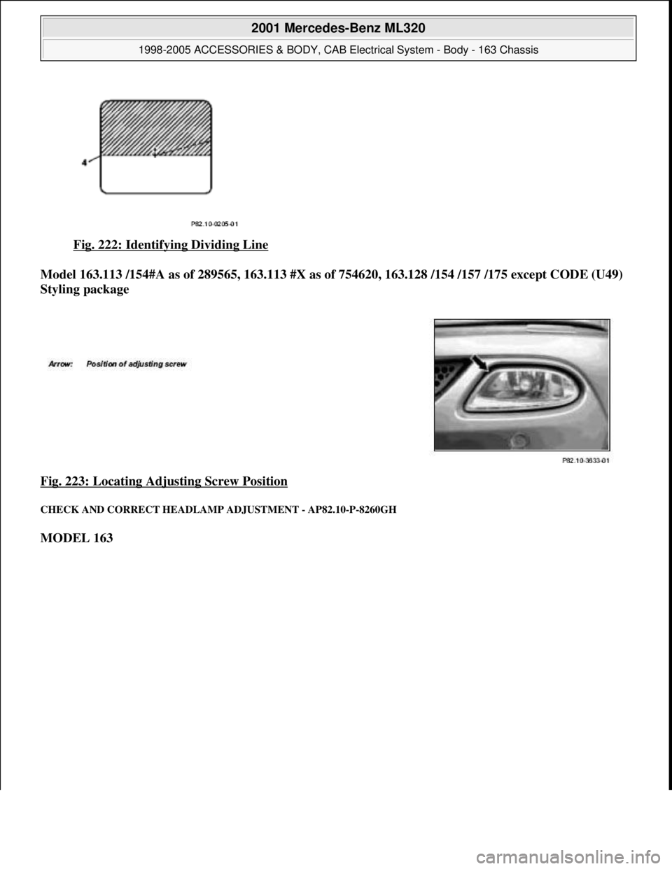
Fig. 222: Identifying Dividing Line
Model 163.113 /154#A as of 289565, 163.113 #X as of 754620, 163.128 /154 /157 /175 except CODE (U49)
Styling package
Fig. 223: Locating Adjusting Screw Position
CHECK AND CORRECT HEADLAMP ADJUSTMENT - AP82.10-P-8260GH
MODEL 163
2001 Mercedes-Benz ML320
1998-2005 ACCESSORIES & BODY, CAB Electr ical System - Body - 163 Chassis
me
Saturday, October 02, 2010 3:30:10 PMPage 323 © 2006 Mitchell Repair Information Company, LLC.
Page 1819 of 4133
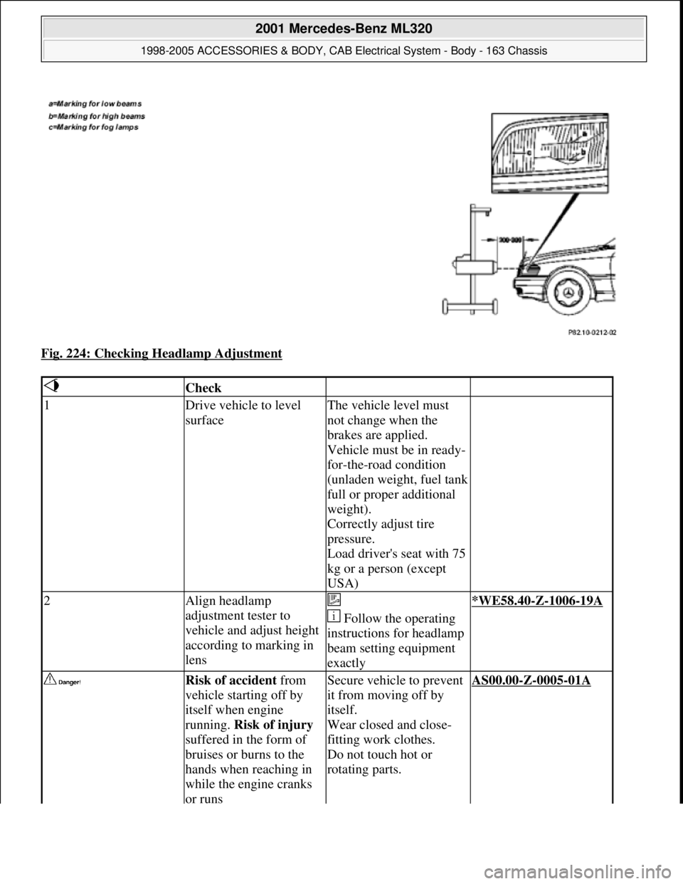
Fig. 224: Checking Headlamp Adjustment
Check
1Drive vehicle to level
surfaceThe vehicle level must
not change when the
brakes are applied.
Vehicle must be in ready-
for-the-road condition
(unladen weight, fuel tank
full or proper additional
weight).
Correctly adjust tire
pressure.
Load driver's seat with 75
kg or a person (except
USA)
2Align headlamp
adjustment tester to
vehicle and adjust height
according to marking in
lens
Follow the operating
instructions for headlamp
beam setting equipment
exactly*WE58.40-Z-1006-19A
Risk of accident from
vehicle starting off by
itself when engine
running. Risk of injury
suffered in the form of
bruises or burns to the
hands when reaching in
while the engine cranks
or runsSecure vehicle to prevent
it from moving off by
itself.
Wear closed and close-
fitting work clothes.
Do not touch hot or
rotating parts.AS00.00-Z-0005-01A
2001 Mercedes-Benz ML320
1998-2005 ACCESSORIES & BODY, CAB Electrical System - Body - 163 Chassis
me
Saturday, October 02, 2010 3:30:10 PMPage 324 © 2006 Mitchell Repair Information Company, LLC.
Page 1820 of 4133
Workshop equipment
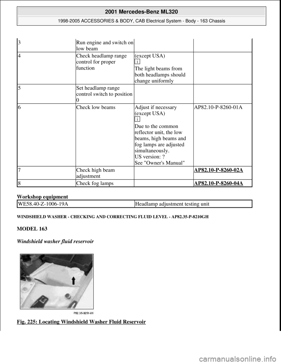
WINDSHIELD WASHER - CHECKING AND CORRECTING FLUID LEVEL - AP82.35-P-8210GH
MODEL 163
Windshield washer fluid reservoir
Fig. 225: Locating Windshield Washer Fluid Reservoir
3Run engine and switch on
low beam
4Check headlamp range
control for proper
function(except USA)
The light beams from
both headlamps should
change uniformly
5Set headlamp range
control switch to position
0
6Check low beamsAdjust if necessary
(except USA)
Due to the common
reflector unit, the low
beams, high beams and
fog lamps are adjusted
simultaneously.
US version: ?
See "Owner's Manual"AP82.10-P-8260-01A
7Check high beam
adjustment AP82.10-P-8260-02A
8Check fog lamps AP82.10-P-8260-04A
WE58.40-Z-1006-19AHeadlamp adjustment testing unit
2001 Mercedes-Benz ML320
1998-2005 ACCESSORIES & BODY, CAB Electrical System - Body - 163 Chassis
me
Saturday, October 02, 2010 3:30:10 PMPage 325 © 2006 Mitchell Repair Information Company, LLC.