MERCEDES-BENZ ML430 1997 Complete Repair Manual
Manufacturer: MERCEDES-BENZ, Model Year: 1997, Model line: ML430, Model: MERCEDES-BENZ ML430 1997Pages: 4133, PDF Size: 88.89 MB
Page 1831 of 4133
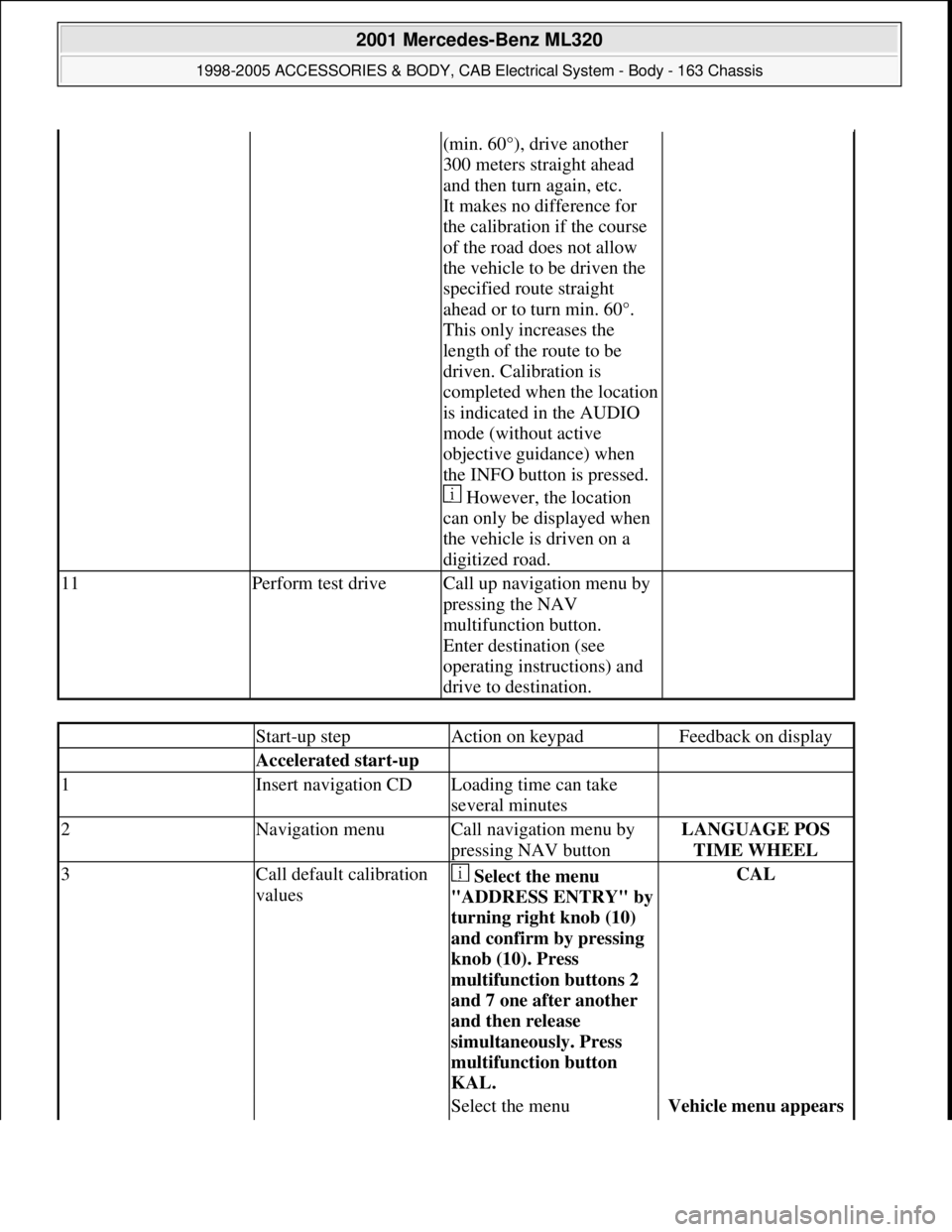
(min. 60°), drive another
300 meters straight ahead
and then turn again, etc.
It makes no difference for
the calibration if the course
of the road does not allow
the vehicle to be driven the
specified route straight
ahead or to turn min. 60°.
This only increases the
length of the route to be
driven. Calibration is
completed when the location
is indicated in the AUDIO
mode (without active
objective guidance) when
the INFO button is pressed.
However, the location
can only be displayed when
the vehicle is driven on a
digitized road.
11Perform test driveCall up navigation menu by
pressing the NAV
multifunction button.
Enter destination (see
operating instructions) and
drive to destination.
Start-up stepAction on keypadFeedback on display
Accelerated start-up
1Insert navigation CDLoading time can take
several minutes
2Navigation menuCall navigation menu by
pressing NAV buttonLANGUAGE POS
TIME WHEEL
3Call default calibration
values Select the menu
"ADDRESS ENTRY" b
y
turning right knob (10)
and confirm by pressing
knob (10). Press
multifunction buttons 2
and 7 one after another
and then release
simultaneously. Press
multifunction button
KAL.
CAL
Select the menu Vehicle menu appears
2001 Mercedes-Benz ML320
1998-2005 ACCESSORIES & BODY, CAB Electrical System - Body - 163 Chassis
me
Saturday, October 02, 2010 3:30:11 PMPage 336 © 2006 Mitchell Repair Information Company, LLC.
Page 1832 of 4133
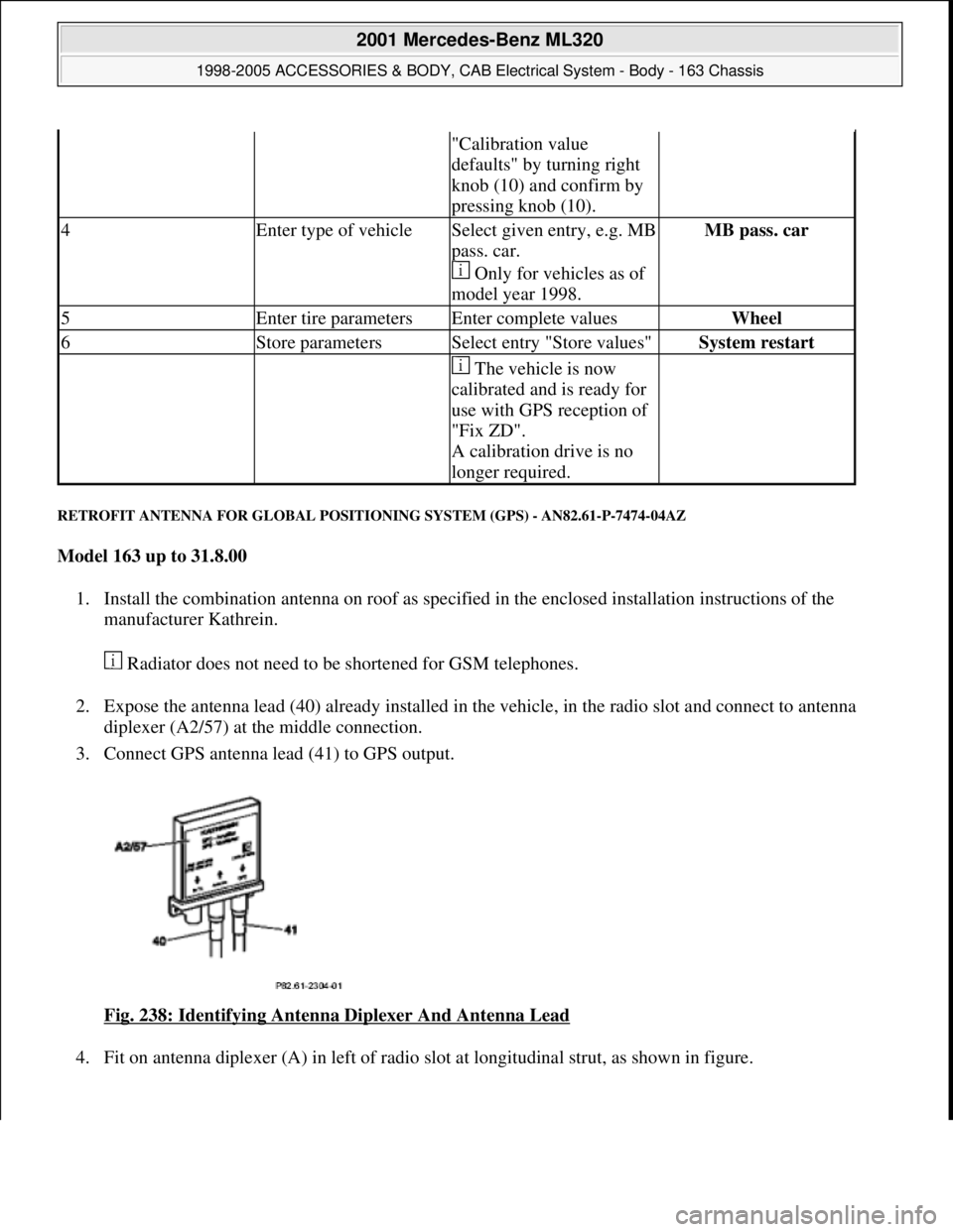
RETROFIT ANTENNA FOR GLOBAL POSITIONING SYSTEM (GPS) - AN82.61-P-7474-04AZ
Model 163 up to 31.8.00
1. Install the combination antenna on roof as specified in the enclosed installation instructions of the
manufacturer Kathrein.
Radiator does not need to be shortened for GSM telephones.
2. Expose the antenna lead (40) already installed in the vehicle, in the radio slot and connect to antenna
diplexer (A2/57) at the middle connection.
3. Connect GPS antenna lead (41) to GPS output.
Fig. 238: Identifying Antenna Diplexer And Antenna Lead
4. Fit on antenna diplexer (A) in left of radio slot at lon
gitudinal strut, as shown in figure.
"Calibration value
defaults" by turning right
knob (10) and confirm by
pressing knob (10).
4Enter type of vehicleSelect given entry, e.g. MB
pass. car.
Only for vehicles as of
model year 1998.MB pass. car
5Enter tire parametersEnter complete valuesWheel
6Store parametersSelect entry "Store values"System restart
The vehicle is now
calibrated and is ready for
use with GPS reception of
"Fix ZD".
A calibration drive is no
longer required.
2001 Mercedes-Benz ML320
1998-2005 ACCESSORIES & BODY, CAB Electrical System - Body - 163 Chassis
me
Saturday, October 02, 2010 3:30:11 PMPage 337 © 2006 Mitchell Repair Information Company, LLC.
Page 1833 of 4133
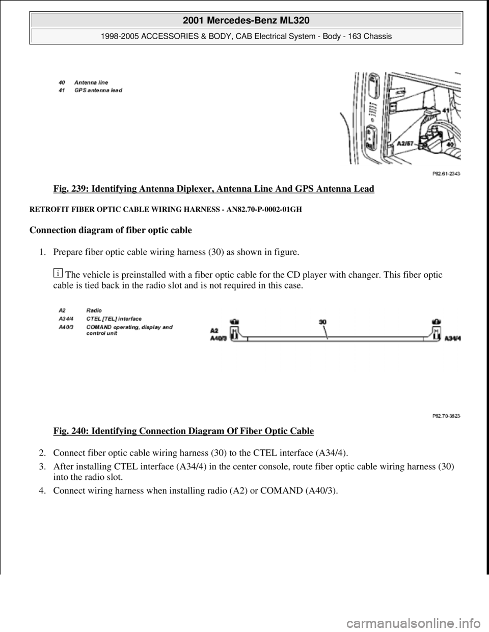
Fig. 239: Identifying Antenna Diplexer, Antenna Line And GPS Antenna Lead
RETROFIT FIBER OPTIC CABLE WIRING HARNESS - AN82.70-P-0002-01GH
Connection diagram of fiber optic cable
1. Prepare fiber optic cable wiring harness (30) as shown in figure.
The vehicle is preinstalled with a fiber optic cable for the CD player with changer. This fiber optic
cable is tied back in the radio slot and is not required in this case.
Fig. 240: Identifying Connection Diagram Of Fiber Optic Cable
2. Connect fiber optic cable wiring harness (30) to the CTEL interface (A34/4).
3. After installing CTEL interface (A34/4) in the center console, route fiber optic cable wiring harness (30)
into the radio slot.
4. Connect wiring harness when installing radio (A2) or COMAND (A40/3).
2001 Mercedes-Benz ML320
1998-2005 ACCESSORIES & BODY, CAB Electrical System - Body - 163 Chassis
me
Saturday, October 02, 2010 3:30:11 PMPage 338 © 2006 Mitchell Repair Information Company, LLC.
Page 1834 of 4133
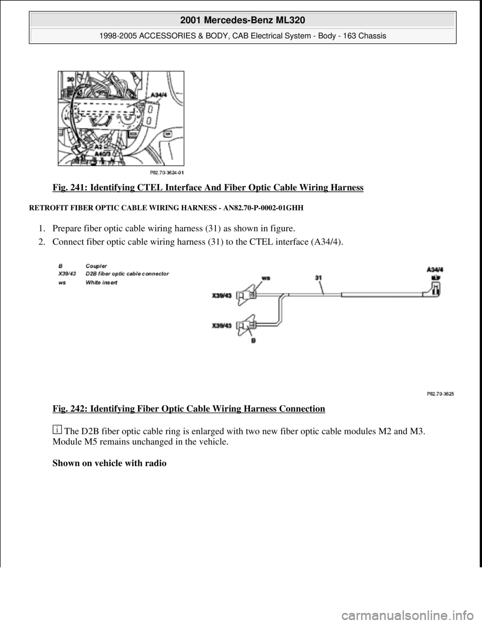
Fig. 241: Identifying CTEL Interface And Fiber Optic Cable Wiring Harness
RETROFIT FIBER OPTIC CABLE WIRING HARNESS - AN82.70-P-0002-01GHH
1. Prepare fiber optic cable wiring harness (31) as shown in figure.
2. Connect fiber optic cable wiring harness (31) to the CTEL interface (A34/4).
Fig. 242: Identifying Fiber Optic Cable Wiring Harness Connection
The D2B fiber optic cable ring is enlarged with two new fiber optic cable modules M2 and M3.
Module M5 remains unchanged in the vehicle.
Shown on vehicle with radio
2001 Mercedes-Benz ML320
1998-2005 ACCESSORIES & BODY, CAB Electrical System - Body - 163 Chassis
me
Saturday, October 02, 2010 3:30:11 PMPage 339 © 2006 Mitchell Repair Information Company, LLC.
Page 1835 of 4133
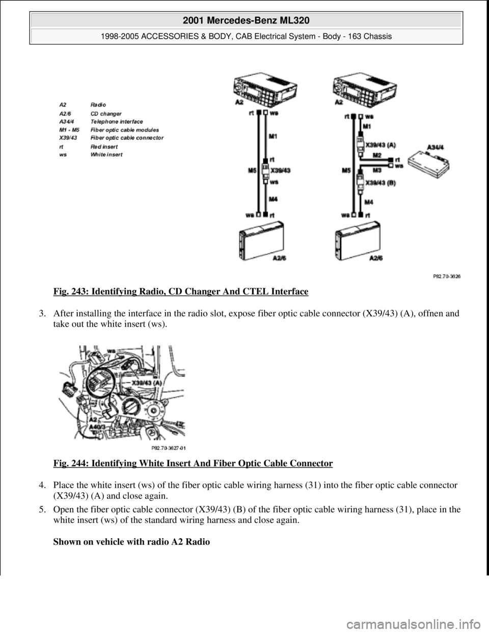
Fig. 243: Identifying Radio, CD Changer And CTEL Interface
3. After installing the interface in the radio slot, expose fiber optic cable connector (X39/43) (A), offnen and
take out the white insert (ws).
Fig. 244: Identifying White Insert And Fiber Optic Cable Connector
4. Place the white insert (ws) of the fiber optic cable wiring harness (31) into the fiber optic cable connector
(X39/43) (A) and close again.
5. Open the fiber optic cable connector (X39/43) (B) of the fiber optic cable wiring harness (31), place in the
white insert (ws) of the standard wiring harness and close again.
Shown on vehicle with radio A2 Radio
2001 Mercedes-Benz ML320
1998-2005 ACCESSORIES & BODY, CAB Electrical System - Body - 163 Chassis
me
Saturday, October 02, 2010 3:30:11 PMPage 340 © 2006 Mitchell Repair Information Company, LLC.
Page 1836 of 4133
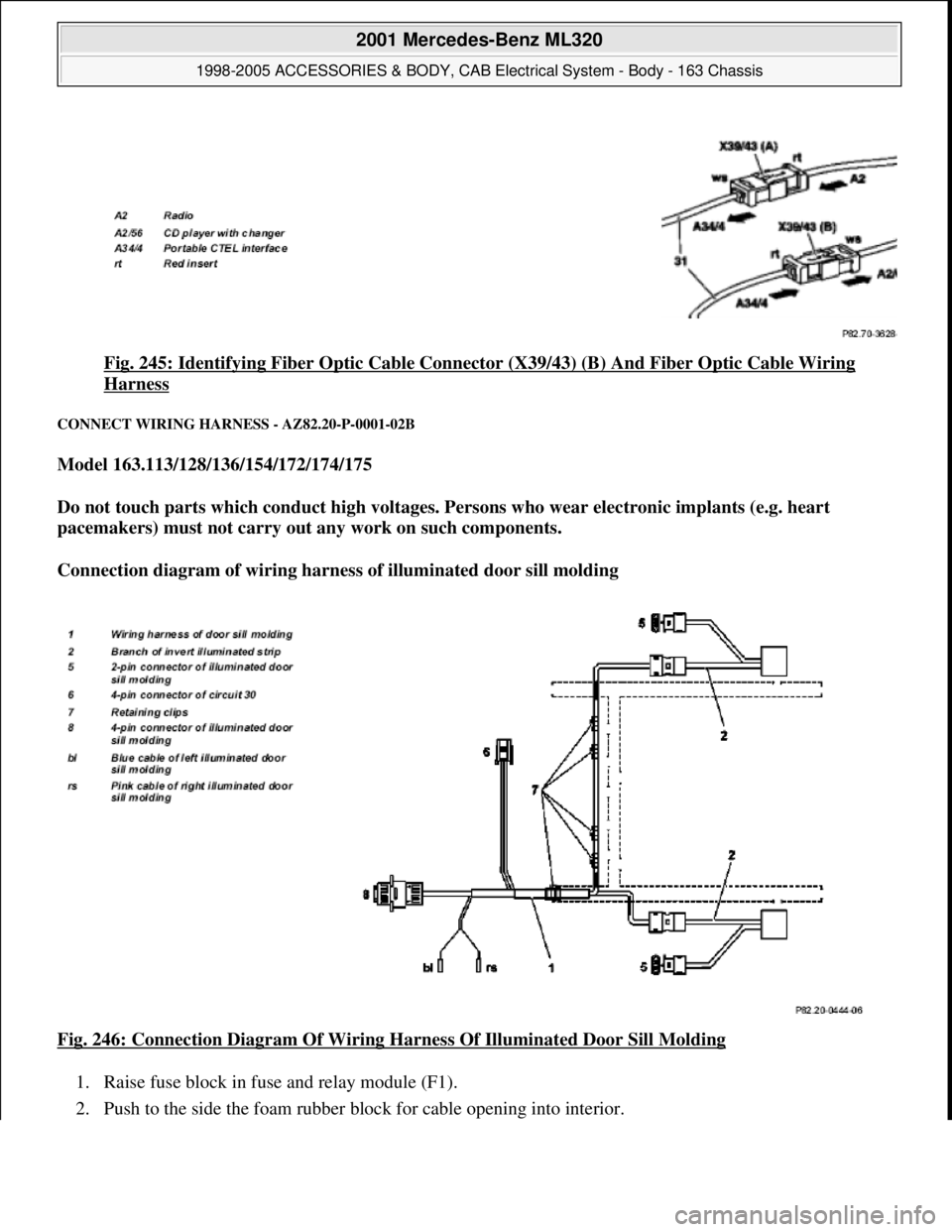
Fig. 245: Identifying Fiber Optic Cable Connector (X39/43) (B) And Fiber Optic Cable Wiring
Harness
CONNECT WIRING HARNESS - AZ82.20-P-0001-02B
Model 163.113/128/136/154/172/174/175
Do not touch parts which conduct high voltages. Persons who wear electronic implants (e.g. heart
pacemakers) must not carry out any work on such components.
Connection diagram of wiring harness of illuminated door sill molding
Fig. 246: Connection Diagram Of Wiring Harness Of Illuminated Door Sill Molding
1. Raise fuse block in fuse and relay module (F1).
2. Push to the side the foam rubber block for cable openin
g into interior.
2001 Mercedes-Benz ML320
1998-2005 ACCESSORIES & BODY, CAB Electrical System - Body - 163 Chassis
me
Saturday, October 02, 2010 3:30:11 PMPage 341 © 2006 Mitchell Repair Information Company, LLC.
Page 1837 of 4133
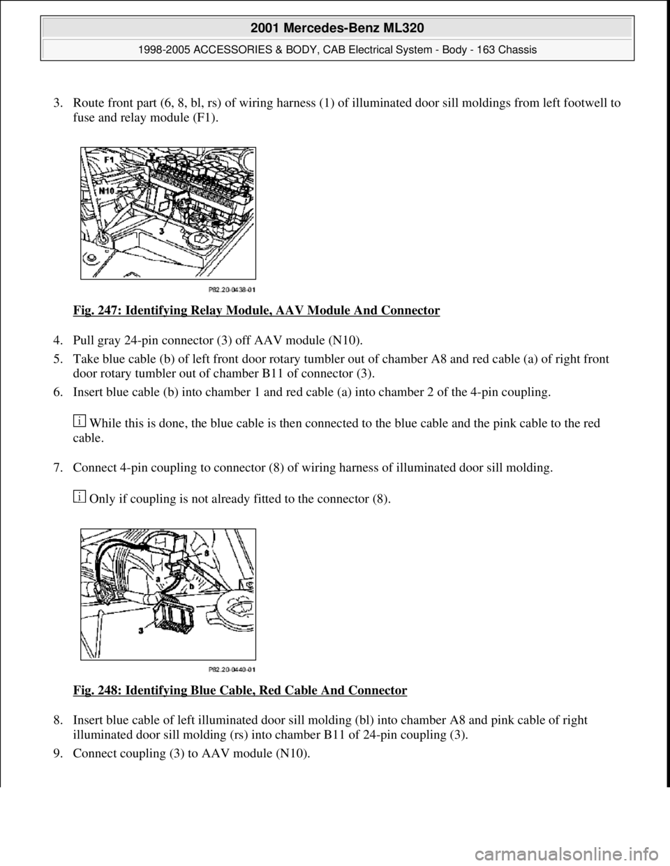
3. Route front part (6, 8, bl, rs) of wiring harness (1) of illuminated door sill moldings from left footwell to
fuse and relay module (F1).
Fig. 247: Identifying Relay Module, AAV Module And Connector
4. Pull gray 24-pin connector (3) off AAV module (N10).
5. Take blue cable (b) of left front door rotary tumbler out of chamber A8 and red cable (a) of right front
door rotary tumbler out of chamber B11 of connector (3).
6. Insert blue cable (b) into chamber 1 and red cable (a) into chamber 2 of the 4-pin coupling.
While this is done, the blue cable is then connected to the blue cable and the pink cable to the red
cable.
7. Connect 4-pin coupling to connector (8) of wiring harness of illuminated door sill molding.
Only if coupling is not already fitted to the connector (8).
Fig. 248: Identifying Blue Cable, Red Cable And Connector
8. Insert blue cable of left illuminated door sill molding (bl) into chamber A8 and pink cable of right
illuminated door sill molding (rs) into chamber B11 of 24-pin coupling (3).
9. Connect couplin
g (3) to AAV module (N10).
2001 Mercedes-Benz ML320
1998-2005 ACCESSORIES & BODY, CAB Electrical System - Body - 163 Chassis
me
Saturday, October 02, 2010 3:30:11 PMPage 342 © 2006 Mitchell Repair Information Company, LLC.
Page 1838 of 4133
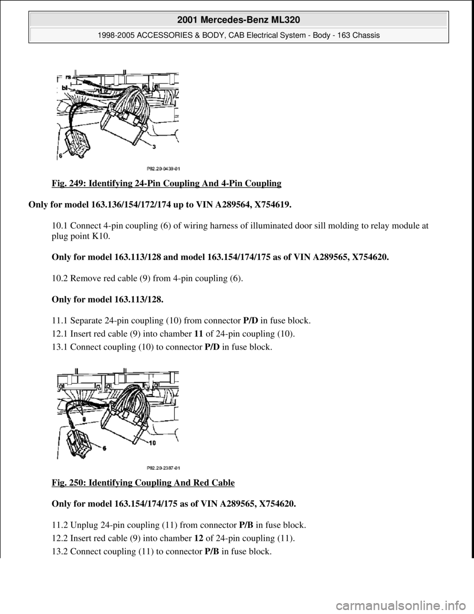
Fig. 249: Identifying 24-Pin Coupling And 4-Pin Coupling
Only for model 163.136/154/172/174 up to VIN A289564, X754619.
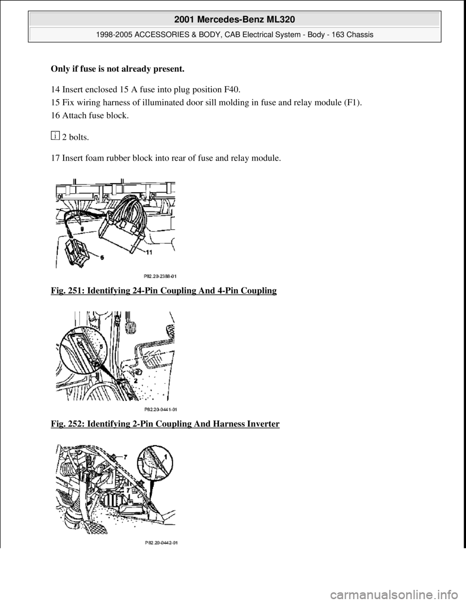
10.1 Connect 4-pin coupling (6) of wiring harness of illuminated door sill molding to relay module at
plug point K10.
Only for model 163.113/128 and mode l 163.154/174/175 as of VIN A289565, X754620.
10.2 Remove red cable (9) from 4-pin coupling (6).
Only for model 163.113/128.
11.1 Separate 24-pin coupli ng (10) from connector P/D in fuse block.
12.1 Insert red cable (9) into chamber 11 of 24-pin coupling (10).
13.1 Connect coupling (10) to connector P/D in fuse block.
Fig. 250: Identifying Coupling And Red Cable
Only for model 163.154/174/ 175 as of VIN A289565, X754620.
11.2 Unplug 24-pin coupling (11) from connector P/B in fuse block.
12.2 Insert red cable (9) into chamber 12 of 24-pin coupling (11).
13.2 Connect couplin
g (11) to connector P/Bin fuse block.
2001 Mercedes-Benz ML320
1998-2005 ACCESSORIES & BODY, CAB Electr ical System - Body - 163 Chassis
me
Saturday, October 02, 2010 3:30:11 PMPage 343 © 2006 Mitchell Repair Information Company, LLC.
Page 1839 of 4133
Only if fuse is not already present.
14 Insert enclosed 15 A fu se into plug position F40.
15 Fix wiring harness of illuminated door sill molding in fuse and relay module (F1).
16 Attach fuse block.
2 bolts.
17 Insert foam rubber block into rear of fuse and relay module.
Fig. 251: Identifying 24
-Pin Coupling And 4-Pin Coupling
Fig. 252: Identifying 2
-Pin Coupling And Harness Inverter
2001 Mercedes-Benz ML320
1998-2005 ACCESSORIES & BODY, CAB Electr ical System - Body - 163 Chassis
me
Saturday, October 02, 2010 3:30:11 PMPage 344 © 2006 Mitchell Repair Information Company, LLC.
Page 1840 of 4133
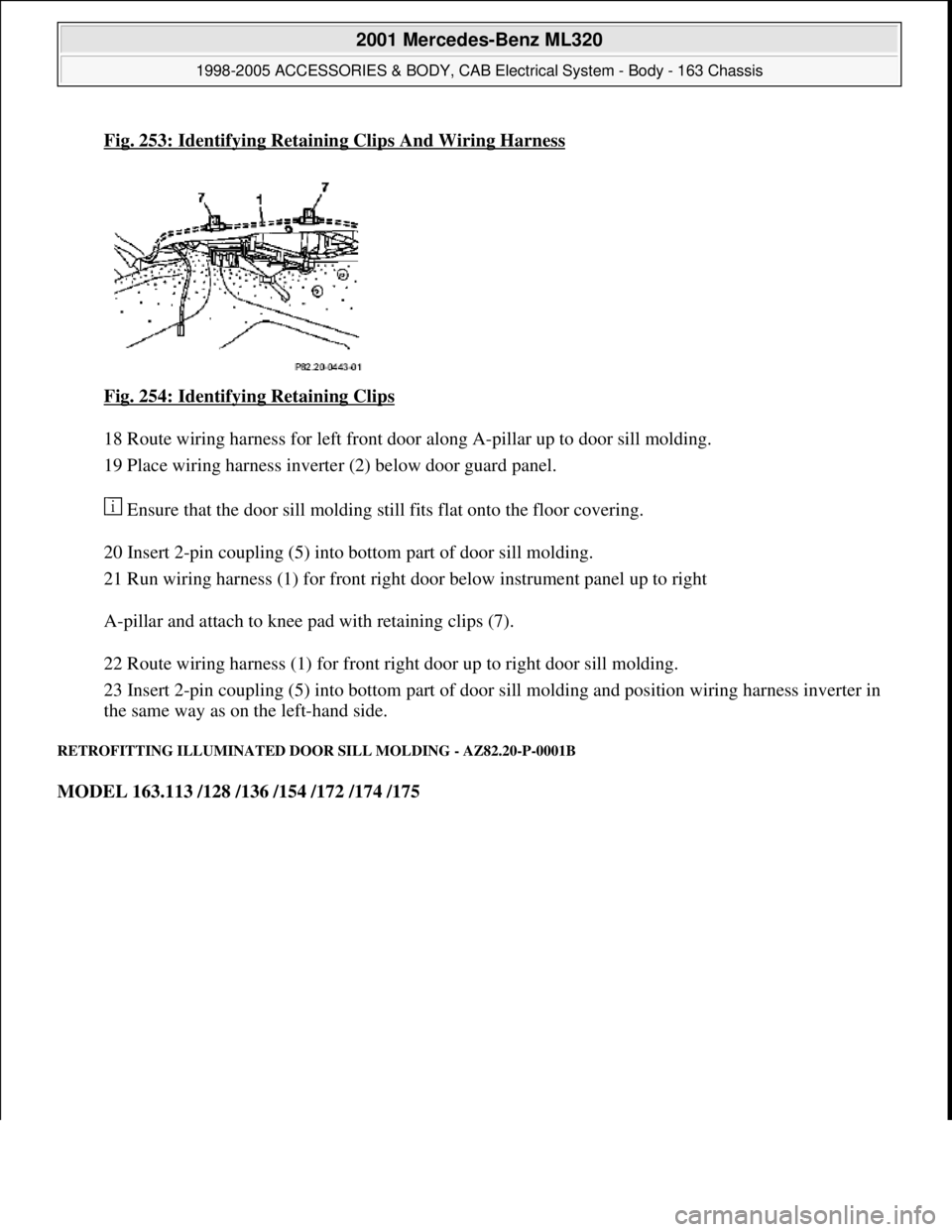
Fig. 253: Identifying Retaining Clips And Wiring Harness
Fig. 254: Identifying Retaining Clips
18 Route wiring harness for left front door along A-pillar up to door sill molding.
19 Place wiring harness inverter (2) below door guard panel.
Ensure that the door sill molding still fits flat onto the floor covering.
20 Insert 2-pin coupling (5) into bottom part of door sill molding.
21 Run wiring harness (1) for front right door below instrument panel up to right
A-pillar and attach to knee pad with retaining clips (7).
22 Route wiring harness (1) for front right door up to right door sill molding.
23 Insert 2-pin coupling (5) into bottom part of door sill molding and position wiring harness inverter in
the same way as on the left-hand side.
RETROFITTING ILLUMINATED DOOR SILL MOLDING - AZ82.20-P-0001B
MODEL 163.113 /128 /136 /154 /172 /174 /175
2001 Mercedes-Benz ML320
1998-2005 ACCESSORIES & BODY, CAB Electrical System - Body - 163 Chassis
me
Saturday, October 02, 2010 3:30:11 PMPage 345 © 2006 Mitchell Repair Information Company, LLC.