MERCEDES-BENZ ML430 1997 Complete Repair Manual
Manufacturer: MERCEDES-BENZ, Model Year: 1997, Model line: ML430, Model: MERCEDES-BENZ ML430 1997Pages: 4133, PDF Size: 88.89 MB
Page 1851 of 4133
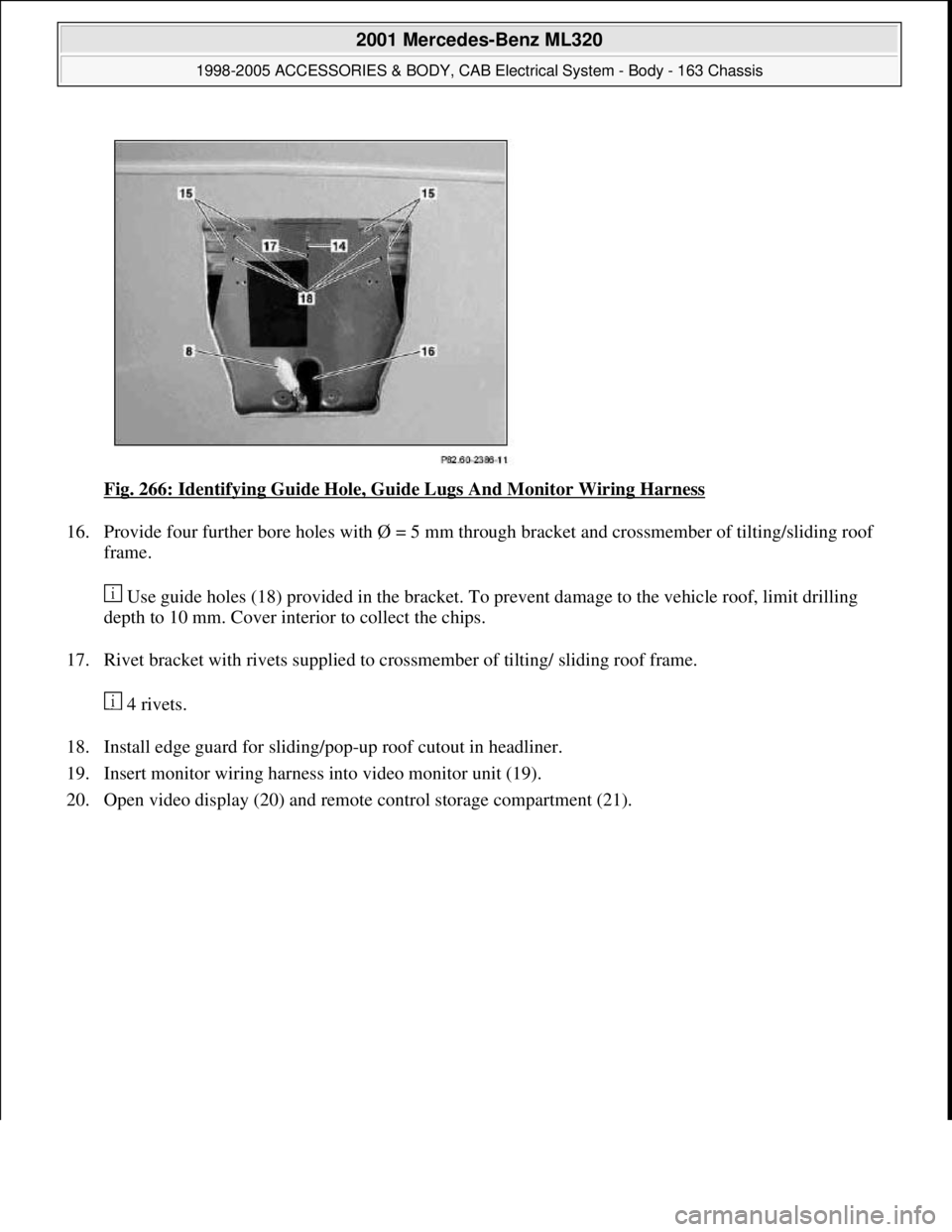
Fig. 266: Identifying Guide Hole, Guide Lugs And Monitor Wiring Harness
16. Provide four further bore holes with Ø = 5 mm through bracket and crossmember of tilting/sliding roof
frame.
Use guide holes (18) provided in the bracket. To prevent damage to the vehicle roof, limit drilling
depth to 10 mm. Cover interior to collect the chips.
17. Rivet bracket with rivets supplied to crossmember of tilting/ sliding roof frame.
4 rivets.
18. Install edge guard for sliding/pop-up roof cutout in headliner.
19. Insert monitor wiring harness into video monitor unit (19).
20. Open video display (20) and remote control storage compartment (21).
2001 Mercedes-Benz ML320
1998-2005 ACCESSORIES & BODY, CAB Electrical System - Body - 163 Chassis
me
Saturday, October 02, 2010 3:30:11 PMPage 356 © 2006 Mitchell Repair Information Company, LLC.
Page 1852 of 4133
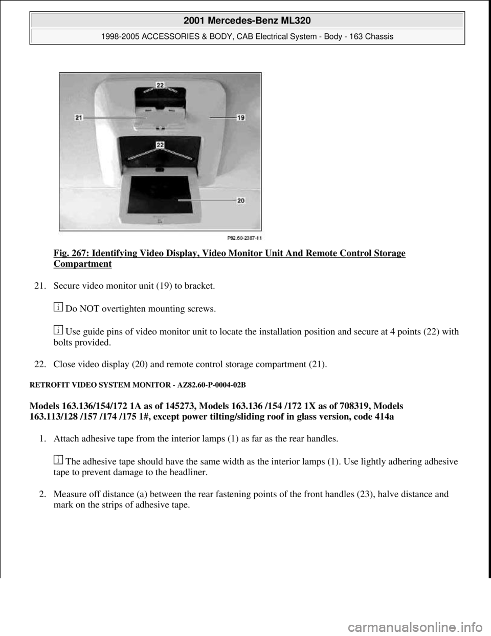
Fig. 267: Identifying Video Display, Video Monitor Unit And Remote Control Storage
Compartment
21. Secure video monitor unit (19) to bracket.
Do NOT overtighten mounting screws.
Use guide pins of video monitor unit to locate the installation position and secure at 4 points (22) with
bolts provided.
22. Close video display (20) and remote control storage compartment (21).
RETROFIT VIDEO SYSTEM MONITOR - AZ82.60-P-0004-02B
Models 163.136/154/172 1A as of 145273, Models 163.136 /154 /172 1X as of 708319, Models
163.113/128 /157 /174 /175 1#, except power tilting/sliding roof in glass version, code 414a
1. Attach adhesive tape from the interior lamps (1) as far as the rear handles.
The adhesive tape should have the same width as the interior lamps (1). Use lightly adhering adhesive
tape to prevent damage to the headliner.
2. Measure off distance (a) between the rear fastening points of the front handles (23), halve distance and
mark on the strips of adhesive tape.
2001 Mercedes-Benz ML320
1998-2005 ACCESSORIES & BODY, CAB Electrical System - Body - 163 Chassis
me
Saturday, October 02, 2010 3:30:11 PMPage 357 © 2006 Mitchell Repair Information Company, LLC.
Page 1853 of 4133
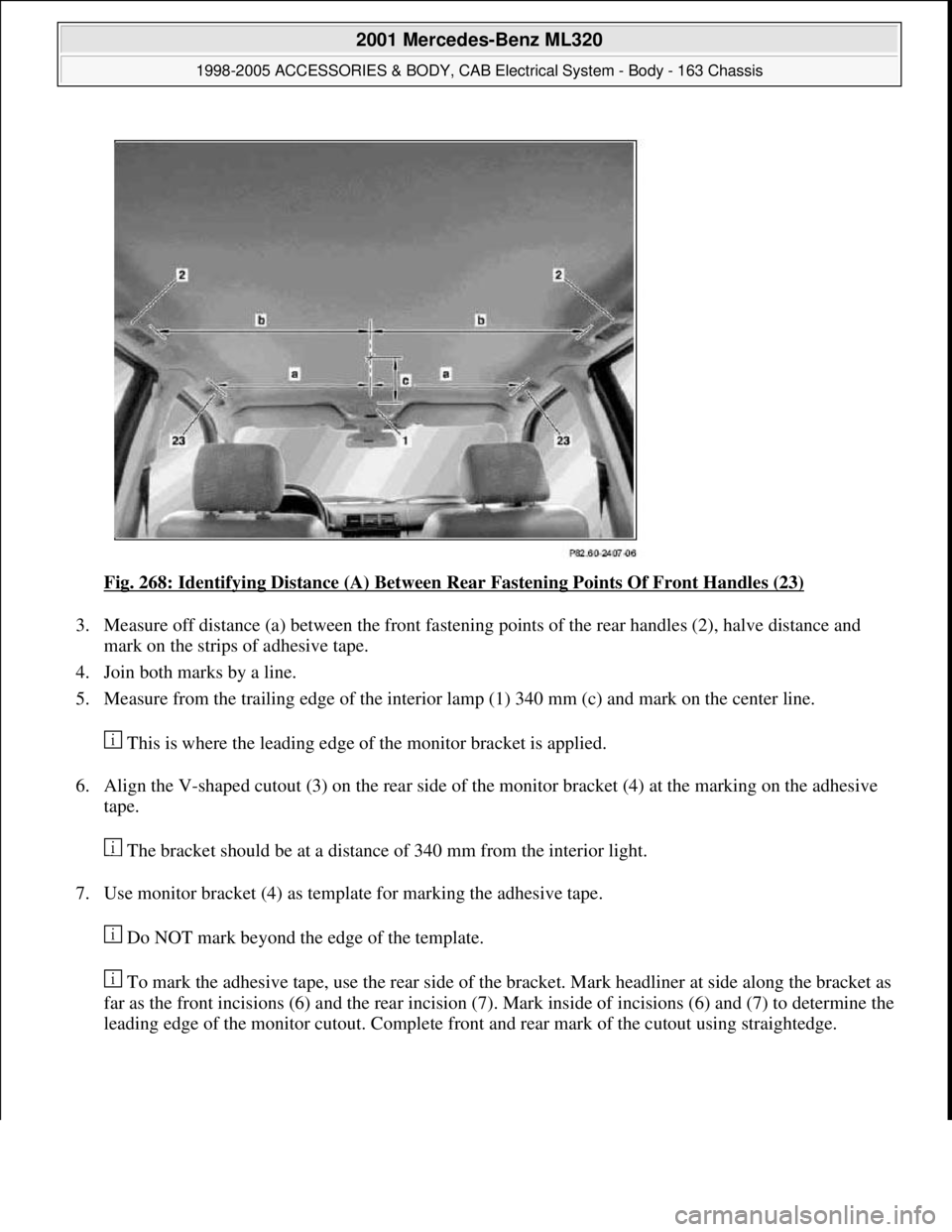
Fig. 268: Identifying Distance (A) Between Rear Fastening Points Of Front Handles (23)
3. Measure off distance (a) between the front fastening points of the rear handles (2), halve distance and
mark on the strips of adhesive tape.
4. Join both marks by a line.
5. Measure from the trailing edge of the interior lamp (1) 340 mm (c) and mark on the center line.
This is where the leading edge of the monitor bracket is applied.
6. Align the V-shaped cutout (3) on the rear side of the monitor bracket (4) at the marking on the adhesive
tape.
The bracket should be at a distance of 340 mm from the interior light.
7. Use monitor bracket (4) as template for marking the adhesive tape.
Do NOT mark beyond the edge of the template.
To mark the adhesive tape, use the rear side of the bracket. Mark headliner at side along the bracket as
far as the front incisions (6) and the rear incision (7). Mark inside of incisions (6) and (7) to determine the
leading edge of the monitor cutout. Complete front and rear mark of the cutout using straightedge.
2001 Mercedes-Benz ML320
1998-2005 ACCESSORIES & BODY, CAB Electrical System - Body - 163 Chassis
me
Saturday, October 02, 2010 3:30:11 PMPage 358 © 2006 Mitchell Repair Information Company, LLC.
Page 1854 of 4133
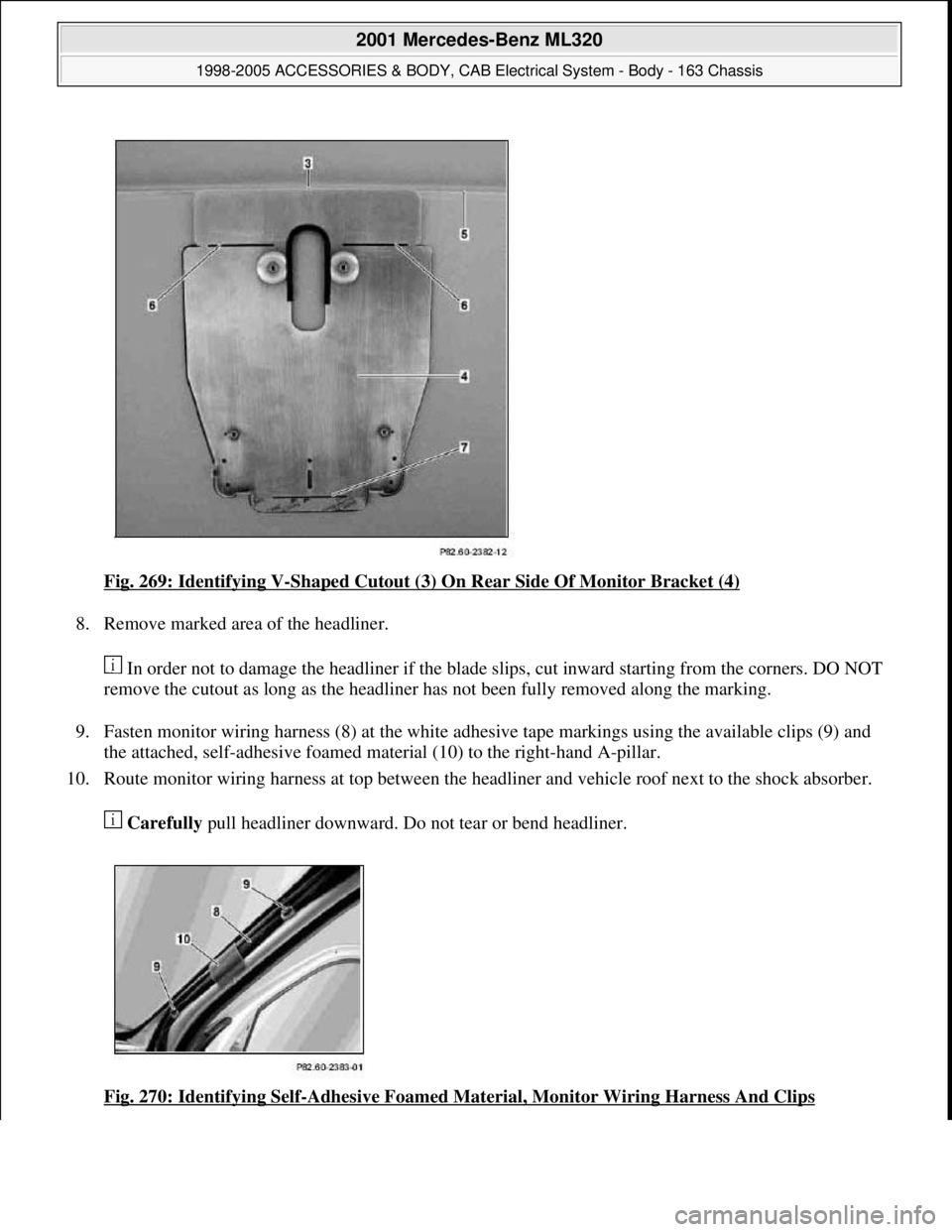
Fig. 269: Identifying V-Shaped Cutout (3) On Rear Side Of Monitor Bracket (4)
8. Remove marked area of the headliner.
In order not to damage the headliner if the blade slips, cut inward starting from the corners. DO NOT
remove the cutout as long as the headliner has not been fully removed along the marking.
9. Fasten monitor wiring harness (8) at the white adhesive tape markings using the available clips (9) and
the attached, self-adhesive foamed material (10) to the right-hand A-pillar.
10. Route monitor wiring harness at top between the headliner and vehicle roof next to the shock absorber.
Carefully pull headliner downward. Do not tear or bend headliner.
Fig. 270: Identifying Self
-Adhesive Foamed Material, Monitor Wiring Harness And Clips
2001 Mercedes-Benz ML320
1998-2005 ACCESSORIES & BODY, CAB Electrical System - Body - 163 Chassis
me
Saturday, October 02, 2010 3:30:11 PMPage 359 © 2006 Mitchell Repair Information Company, LLC.
Page 1855 of 4133
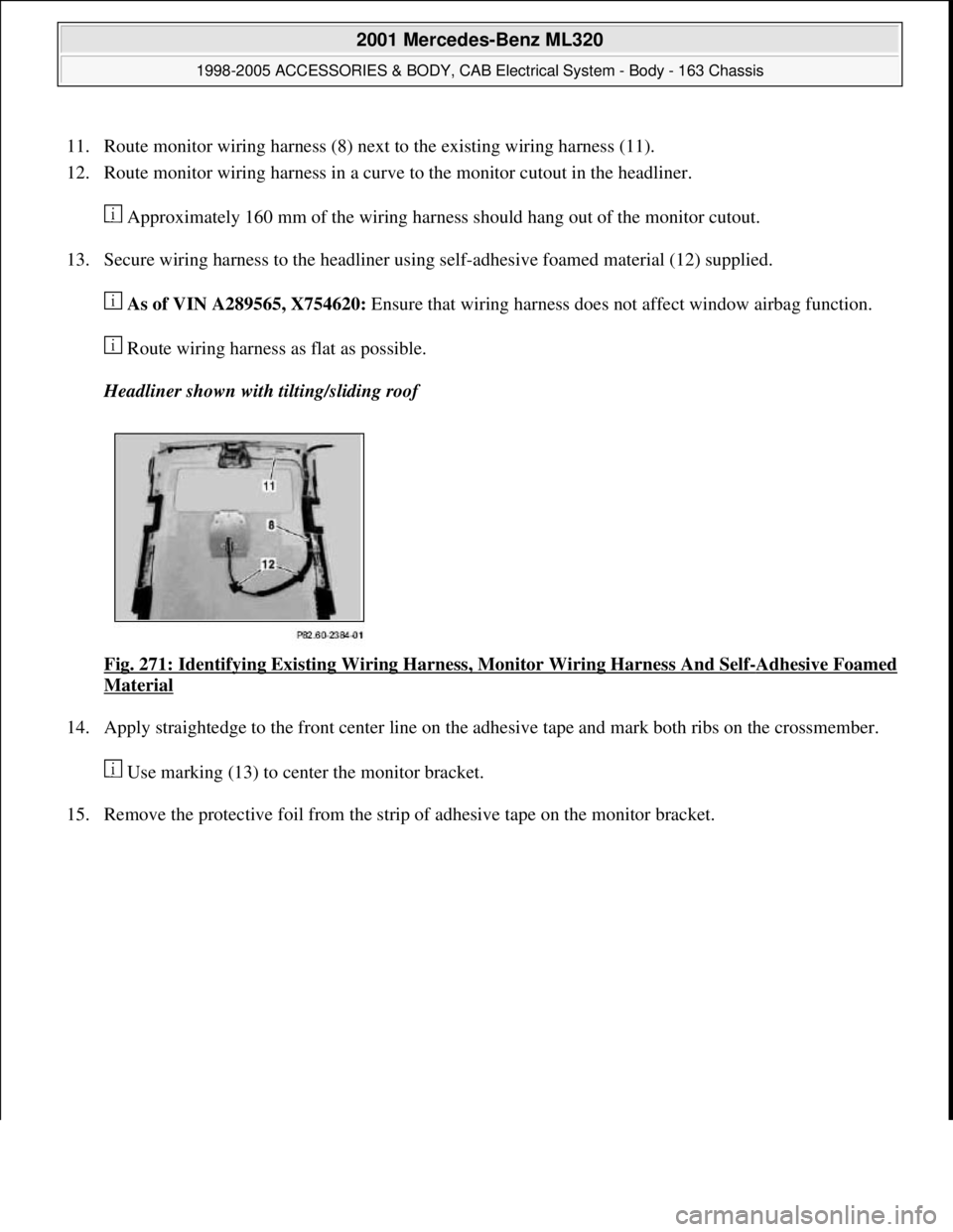
11. Route monitor wiring harness (8) next to the existing wiring harness (11).
12. Route monitor wiring harness in a curve to the monitor cutout in the headliner.
Approximately 160 mm of the wiring harness should hang out of the monitor cutout.
13. Secure wiring harness to the headliner using self-adhesive foamed material (12) supplied.
As of VIN A289565, X754620: Ensure that wiring harness does not affect window airbag function.
Route wiring harness as flat as possible.
Headliner shown with tilting/sliding roof
Fig. 271: Identifying Existing Wiring Harness, Monitor Wiring Harness And Self
-Adhesive Foamed
Material
14. Apply straightedge to the front center line on the adhesive tape and mark both ribs on the crossmember.
Use marking (13) to center the monitor bracket.
15. Remove the protective foil from the strip of adhesive tape on the monitor bracket.
2001 Mercedes-Benz ML320
1998-2005 ACCESSORIES & BODY, CAB Electrical System - Body - 163 Chassis
me
Saturday, October 02, 2010 3:30:11 PMPage 360 © 2006 Mitchell Repair Information Company, LLC.
Page 1856 of 4133
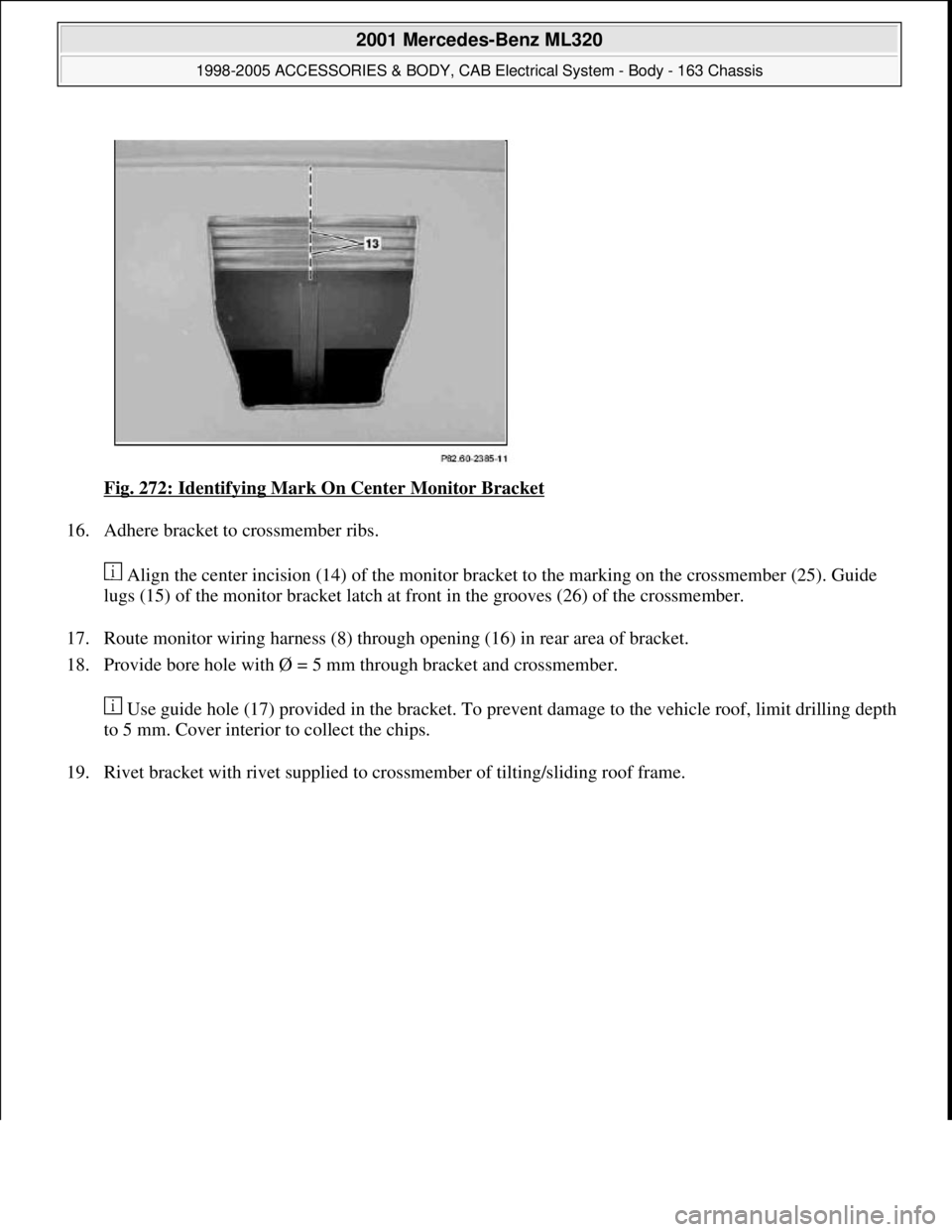
Fig. 272: Identifying Mark On Center Monitor Bracket
16. Adhere bracket to crossmember ribs.
Align the center incision (14) of the monitor bracket to the marking on the crossmember (25). Guide
lugs (15) of the monitor bracket latch at front in the grooves (26) of the crossmember.
17. Route monitor wiring harness (8) through opening (16) in rear area of bracket.
18. Provide bore hole with Ø = 5 mm through bracket and crossmember.
Use guide hole (17) provided in the bracket. To prevent damage to the vehicle roof, limit drilling depth
to 5 mm. Cover interior to collect the chips.
19. Rivet bracket with rivet supplied to crossmember of tiltin
g/sliding roof frame.
2001 Mercedes-Benz ML320
1998-2005 ACCESSORIES & BODY, CAB Electrical System - Body - 163 Chassis
me
Saturday, October 02, 2010 3:30:11 PMPage 361 © 2006 Mitchell Repair Information Company, LLC.
Page 1857 of 4133
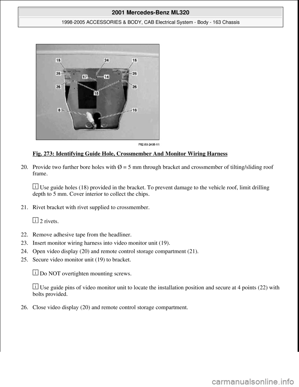
Fig. 273: Identifying Guide Hole, Crossmember And Monitor Wiring Harness
20. Provide two further bore holes with Ø = 5 mm through bracket and crossmember of tilting/sliding roof
frame.
Use guide holes (18) provided in the bracket. To prevent damage to the vehicle roof, limit drilling
depth to 5 mm. Cover interior to collect the chips.
21. Rivet bracket with rivet supplied to crossmember.
2 rivets.
22. Remove adhesive tape from the headliner.
23. Insert monitor wiring harness into video monitor unit (19).
24. Open video display (20) and remote control storage compartment (21).
25. Secure video monitor unit (19) to bracket.
Do NOT overtighten mounting screws.
Use guide pins of video monitor unit to locate the installation position and secure at 4 points (22) with
bolts provided.
26. Close video display (20) and remote control storage compartment.
2001 Mercedes-Benz ML320
1998-2005 ACCESSORIES & BODY, CAB Electrical System - Body - 163 Chassis
me
Saturday, October 02, 2010 3:30:11 PMPage 362 © 2006 Mitchell Repair Information Company, LLC.
Page 1858 of 4133
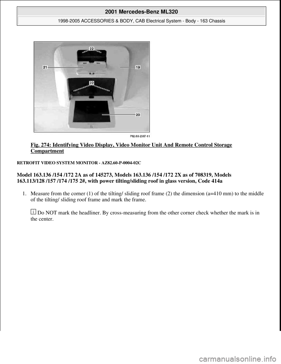
Fig. 274: Identifying Video Display, Video Monitor Unit And Remote Control Storage
Compartment
RETROFIT VIDEO SYSTEM MONITOR - AZ82.60-P-0004-02C
Model 163.136 /154 /172 2A as of 145273, Models 163.136 /154 /172 2X as of 708319, Models
163.113/128 /157 /174 /175 2#, with power tilting/sliding roof in glass version, Code 414a
1. Measure from the corner (1) of the tilting/ sliding roof frame (2) the dimension (a=410 mm) to the middle
of the tilting/ sliding roof frame and mark the frame.
Do NOT mark the headliner. By cross-measuring from the other corner check whether the mark is in
the center.
2001 Mercedes-Benz ML320
1998-2005 ACCESSORIES & BODY, CAB Electrical System - Body - 163 Chassis
me
Saturday, October 02, 2010 3:30:11 PMPage 363 © 2006 Mitchell Repair Information Company, LLC.
Page 1859 of 4133
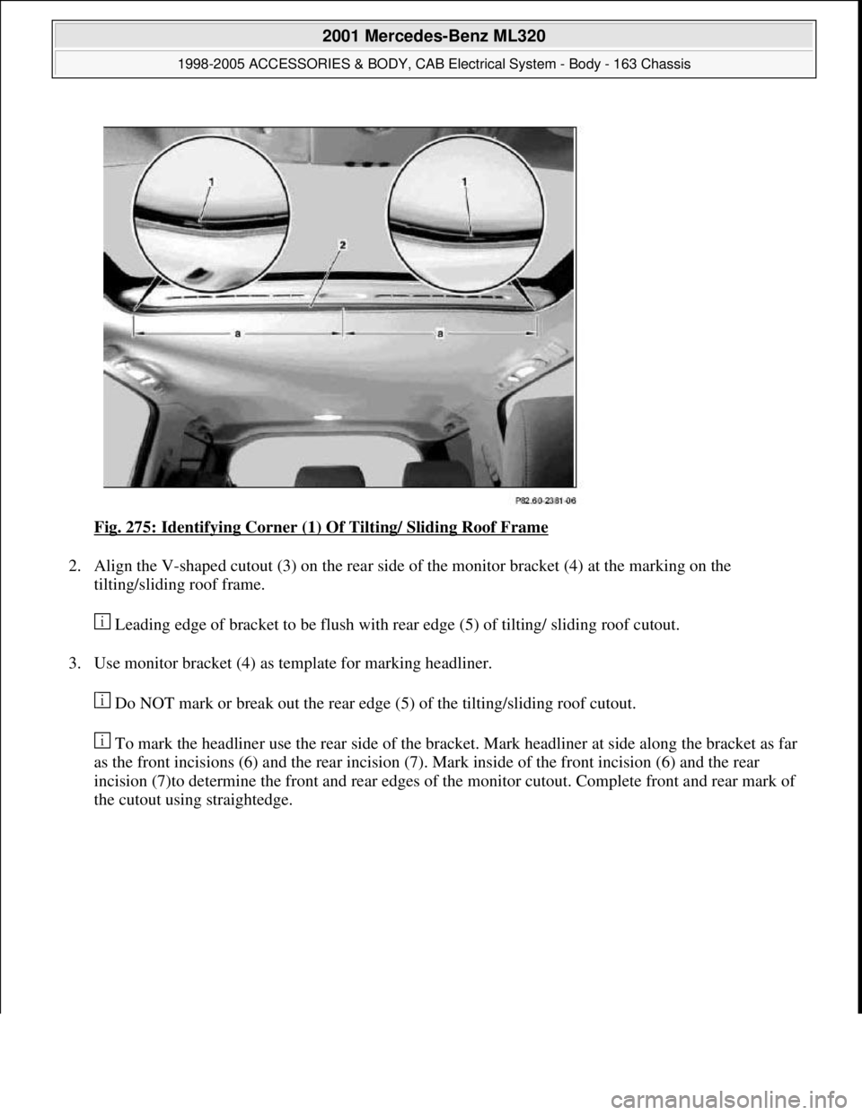
Fig. 275: Identifying Corner (1) Of Tilting/ Sliding Roof Frame
2. Align the V-shaped cutout (3) on the rear side of the monitor bracket (4) at the marking on the
tilting/sliding roof frame.
Leading edge of bracket to be flush with rear edge (5) of tilting/ sliding roof cutout.
3. Use monitor bracket (4) as template for marking headliner.
Do NOT mark or break out the rear edge (5) of the tilting/sliding roof cutout.
To mark the headliner use the rear side of the bracket. Mark headliner at side along the bracket as far
as the front incisions (6) and the rear incision (7). Mark inside of the front incision (6) and the rear
incision (7)to determine the front and rear edges of the monitor cutout. Complete front and rear mark of
the cutout usin
g straightedge.
2001 Mercedes-Benz ML320
1998-2005 ACCESSORIES & BODY, CAB Electrical System - Body - 163 Chassis
me
Saturday, October 02, 2010 3:30:11 PMPage 364 © 2006 Mitchell Repair Information Company, LLC.
Page 1860 of 4133
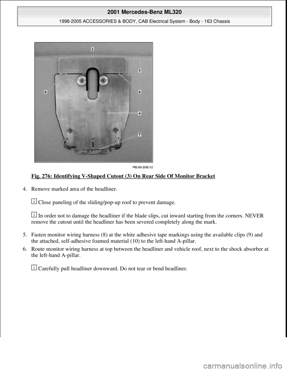
Fig. 276: Identifying V-Shaped Cutout (3) On Rear Side Of Monitor Bracket
4. Remove marked area of the headliner.
Close paneling of the sliding/pop-up roof to prevent damage.
In order not to damage the headliner if the blade slips, cut inward starting from the corners. NEVER
remove the cutout until the headliner has been severed completely along the mark.
5. Fasten monitor wiring harness (8) at the white adhesive tape markings using the available clips (9) and
the attached, self-adhesive foamed material (10) to the left-hand A-pillar.
6. Route monitor wiring harness at top between the headliner and vehicle roof, next to the shock absorber at
the left-hand A-pillar.
Carefull
y pull headliner downward. Do not tear or bend headliner.
2001 Mercedes-Benz ML320
1998-2005 ACCESSORIES & BODY, CAB Electrical System - Body - 163 Chassis
me
Saturday, October 02, 2010 3:30:11 PMPage 365 © 2006 Mitchell Repair Information Company, LLC.