MERCEDES-BENZ ML430 1997 Complete Repair Manual
Manufacturer: MERCEDES-BENZ, Model Year: 1997, Model line: ML430, Model: MERCEDES-BENZ ML430 1997Pages: 4133, PDF Size: 88.89 MB
Page 1841 of 4133
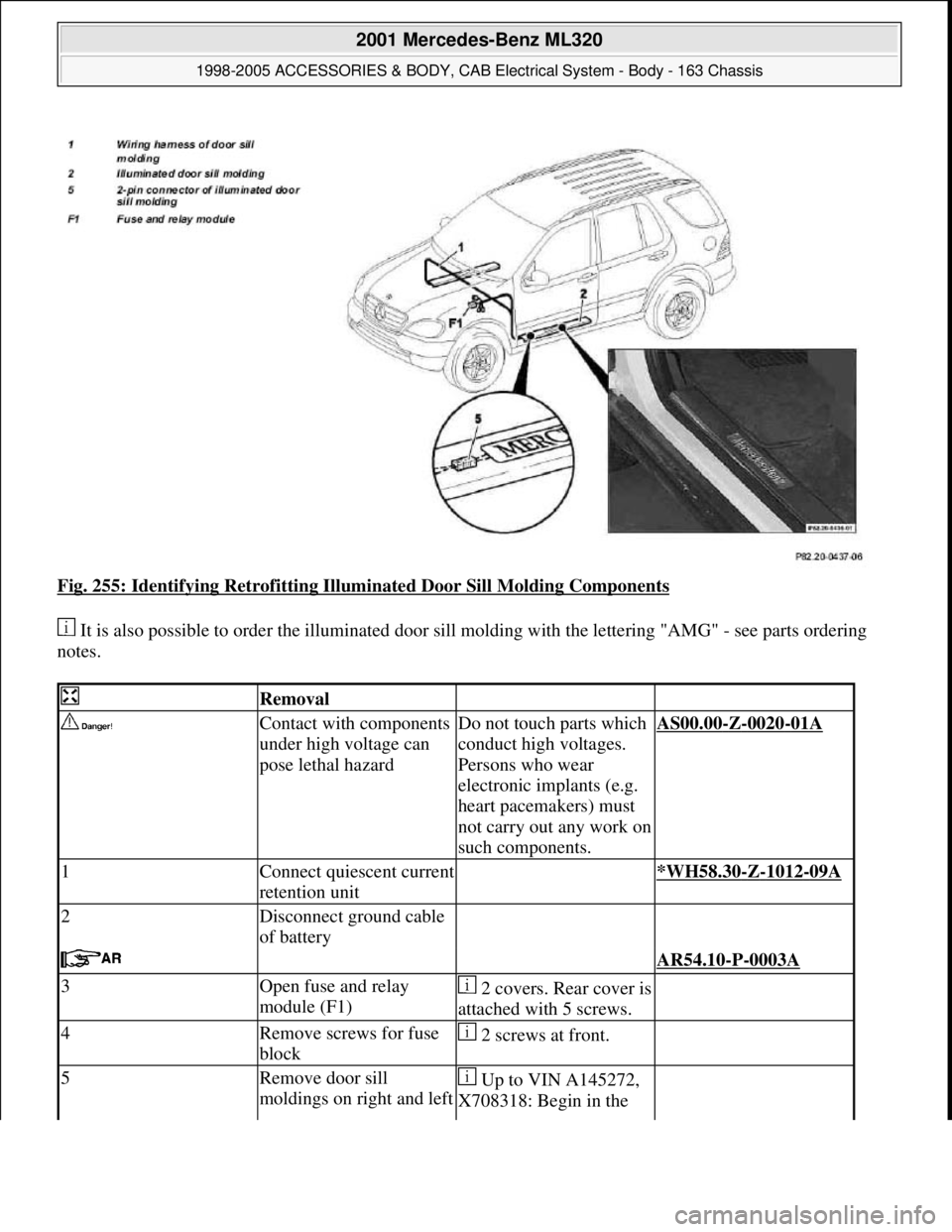
Fig. 255: Identifying Retrofitting Illuminated Door Sill Molding Components
It is also possible to order the illuminated door sill molding with the lettering "AMG" - see parts ordering
notes.
Removal
Contact with components
under high voltage can
pose lethal hazardDo not touch parts which
conduct high voltages.
Persons who wear
electronic implants (e.g.
heart pacemakers) must
not carry out any work on
such components.AS00.00-Z-0020-01A
1Connect quiescent current
retention unit *WH58.30-Z-1012-09A
2Disconnect ground cable
of battery
AR54.10-P-0003A
3Open fuse and relay
module (F1)2 covers. Rear cover is
attached with 5 screws.
4Remove screws for fuse
block 2 screws at front.
5Remove door sill
moldings on right and left Up to VIN A145272,
X708318: Begin in the
2001 Mercedes-Benz ML320
1998-2005 ACCESSORIES & BODY, CAB Electrical System - Body - 163 Chassis
me
Saturday, October 02, 2010 3:30:11 PMPage 346 © 2006 Mitchell Repair Information Company, LLC.
Page 1842 of 4133
driver sidemiddle in order to avoid
damaging the retaining
clips.
As of VINA145273,
X708319: Begin at the
front in order to avoid
damaging the retaining
clips.
Fig. 155
6Take out the two
frontmost screws of the
door sill molding at the
right and left driver side
7Pull off door rubber seal
at bottom of right and left
driver door
8Remove cover below left
of instrument panel
AR68.10-P-1500GH
9Remove cover below
instrument panel on right
Up to VIN A145272,
X708318AR68.10-P-1520GH
As of VIN A145273,
X708319AR68.10-P-1520GI
10Remove right and left
paneling in footwell
AR68.30-P-4010GH
Install
11Install wiring harness for
illuminated door sill
molding and connect AZ82.20-P-0001-02B
12Insert the front screws of
the right and left door sill
molding trim
13Stick luminous foil onto
rear of illuminated door
sill molding The silver side of the
luminous foil is the
underside. Pull off
protective foil of the
double-sided adhesive
tape on the rear of the
door sill molding and
stick on luminous foil.
14Connect illuminated door
2001 Mercedes-Benz ML320
1998-2005 ACCESSORIES & BODY, CAB Electrical System - Body - 163 Chassis
me
Saturday, October 02, 2010 3:30:11 PMPage 347 © 2006 Mitchell Repair Information Company, LLC.
Page 1843 of 4133
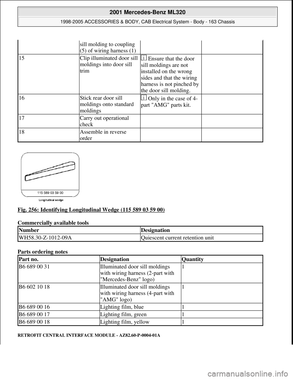
Fig. 256: Identifying Longitudinal Wedge (115 589 03 59 00)
Commercially available tools
Parts ordering notes
RETROFIT CENTRAL INTERFACE MODULE - AZ82.60-P-0004-01A
sill molding to coupling
(5) of wiring harness (1)
15Clip illuminated door sill
moldings into door sill
trim Ensure that the door
sill moldings are not
installed on the wrong
sides and that the wiring
harness is not pinched by
the door sill molding.
16Stick rear door sill
moldings onto standard
moldings Only in the case of 4-
part "AMG" parts kit.
17Carry out operational
check
18Assemble in reverse
order
NumberDesignation
WH58.30-Z-1012-09AQuiescent current retention unit
Part no.DesignationQuantity
B6 689 00 31Illuminated door sill moldings
with wiring harness (2-part with
"Mercedes-Benz" logo)1
B6 602 10 18Illuminated door sill moldings
with wiring harness (4-part with
"AMG" logo)1
B6 689 00 16Lighting film, blue1
B6 689 00 17Lighting film, green1
B6 689 00 18Lighting film, yellow1
2001 Mercedes-Benz ML320
1998-2005 ACCESSORIES & BODY, CAB Electrical System - Body - 163 Chassis
me
Saturday, October 02, 2010 3:30:11 PMPage 348 © 2006 Mitchell Repair Information Company, LLC.
Page 1844 of 4133
Models 163.136/154/172 1A as of 145273, Models 163.136/154/172 1X as of 708319, Models
163.113/128 /157 /174 /175 1#
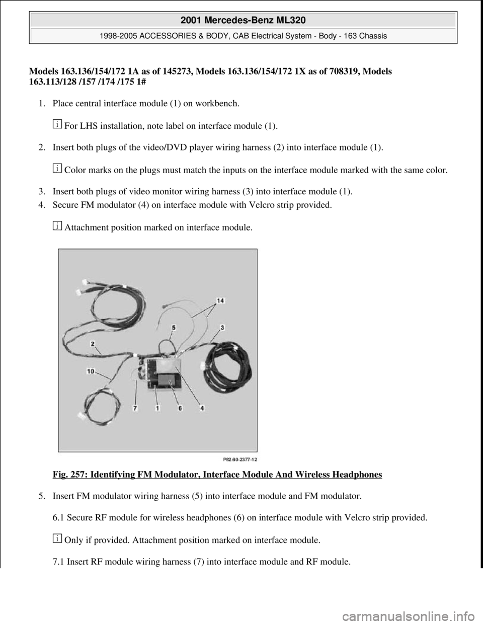
1. Place central interface module (1) on workbench.
For LHS installation, note label on interface module (1).
2. Insert both plugs of the video/DVD player wiring harness (2) into interface module (1).
Color marks on the plugs must match the inputs on the interface module marked with the same color.
3. Insert both plugs of video monitor wiring harness (3) into interface module (1).
4. Secure FM modulator (4) on interface module with Velcro strip provided.
Attachment position marked on interface module.
Fig. 257: Identifying FM Modulator, Interface Module And Wireless Headphones
5. Insert FM modulator wiring harness (5) into interface module and FM modulator.
6.1 Secure RF module for wireless headphones (6) on interface module with Velcro strip provided.
Only if provided. Attachment position marked on interface module.
7.1 Insert RF module wirin
g harness (7) into interface module and RF module.
2001 Mercedes-Benz ML320
1998-2005 ACCESSORIES & BODY, CAB Electrical System - Body - 163 Chassis
me
Saturday, October 02, 2010 3:30:11 PMPage 349 © 2006 Mitchell Repair Information Company, LLC.
Page 1845 of 4133
If fitted.
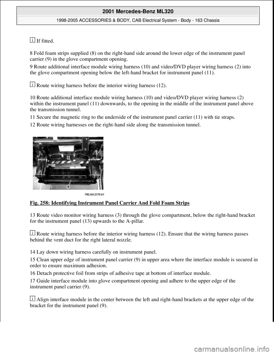
8 Fold foam strips supplied (8) on the right-hand side around the lower edge of the instrument panel
carrier (9) in the glove compartment opening.
9 Route additional interface module wiring harness (10) and video/DVD player wiring harness (2) into
the glove compartment opening below the left-hand bracket for instrument panel (11).
Route wiring harness before the interior wiring harness (12).
10 Route additional interface module wiring harness (10) and video/DVD player wiring harness (2)
within the instrument panel (11) downwards, to the opening in the middle of the instrument panel above
the transmission tunnel.
11 Secure the magnetic ring to the underside of the instrument panel carrier (11) with tie straps.
12 Route wiring harnesses on the right-hand side along the transmission tunnel.
Fig. 258: Identifying Instrument Panel Carrier And Fold Foam Strips
13 Route video monitor wiring harness (3) through the glove compartment, below the right-hand bracket
for the instrument panel (13) upwards to the A-pillar.
Route wiring harness before the interior wiring harness (12). Ensure that the wiring harness passes
behind the vent duct for the right lateral nozzle.
14 Lay down wiring harness carefully on instrument panel.
15 Clean upper edge of instrument panel carrier (9) in upper area where the interface module is secured in
order to ensure maximum adhesion.
16 Detach protective foil from strips of adhesive tape at bottom of interface module.
17 Guide interface module into glove compartment opening and adhere to the upper edge of the
instrument panel carrier (9).
Align interface module in the center between the left and right-hand brackets at the upper edge of the
bracket for the instrument panel (9).
2001 Mercedes-Benz ML320
1998-2005 ACCESSORIES & BODY, CAB Electrical System - Body - 163 Chassis
me
Saturday, October 02, 2010 3:30:11 PMPage 350 © 2006 Mitchell Repair Information Company, LLC.
Page 1846 of 4133
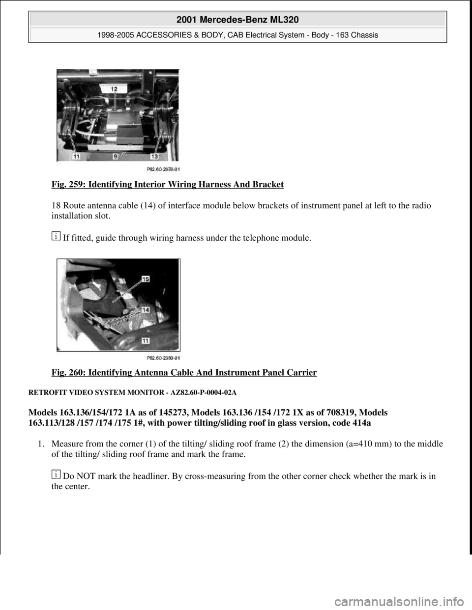
Fig. 259: Identifying Interior Wiring Harness And Bracket
18 Route antenna cable (14) of interface module below brackets of instrument panel at left to the radio
installation slot.
If fitted, guide through wiring harness under the telephone module.
Fig. 260: Identifying Antenna Cable And Instrument Panel Carrier
RETROFIT VIDEO SYSTEM MONITOR - AZ82.60-P-0004-02A
Models 163.136/154/172 1A as of 145273, Models 163.136 /154 /172 1X as of 708319, Models
163.113/128 /157 /174 /175 1#, with power tilting/sliding roof in glass version, code 414a
1. Measure from the corner (1) of the tilting/ sliding roof frame (2) the dimension (a=410 mm) to the middle
of the tilting/ sliding roof frame and mark the frame.
Do NOT mark the headliner. By cross-measuring from the other corner check whether the mark is in
the center.
2001 Mercedes-Benz ML320
1998-2005 ACCESSORIES & BODY, CAB Electrical System - Body - 163 Chassis
me
Saturday, October 02, 2010 3:30:11 PMPage 351 © 2006 Mitchell Repair Information Company, LLC.
Page 1847 of 4133
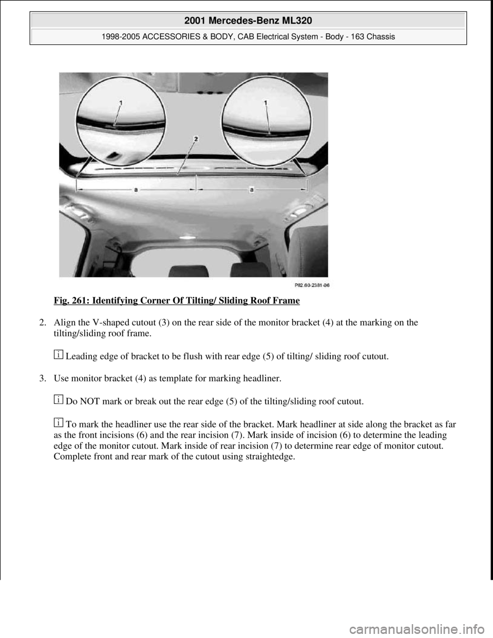
Fig. 261: Identifying Corner Of Tilting/ Sliding Roof Frame
2. Align the V-shaped cutout (3) on the rear side of the monitor bracket (4) at the marking on the
tilting/sliding roof frame.
Leading edge of bracket to be flush with rear edge (5) of tilting/ sliding roof cutout.
3. Use monitor bracket (4) as template for marking headliner.
Do NOT mark or break out the rear edge (5) of the tilting/sliding roof cutout.
To mark the headliner use the rear side of the bracket. Mark headliner at side along the bracket as far
as the front incisions (6) and the rear incision (7). Mark inside of incision (6) to determine the leading
edge of the monitor cutout. Mark inside of rear incision (7) to determine rear edge of monitor cutout.
Complete front and rear mark of the cutout usin
g straightedge.
2001 Mercedes-Benz ML320
1998-2005 ACCESSORIES & BODY, CAB Electrical System - Body - 163 Chassis
me
Saturday, October 02, 2010 3:30:11 PMPage 352 © 2006 Mitchell Repair Information Company, LLC.
Page 1848 of 4133
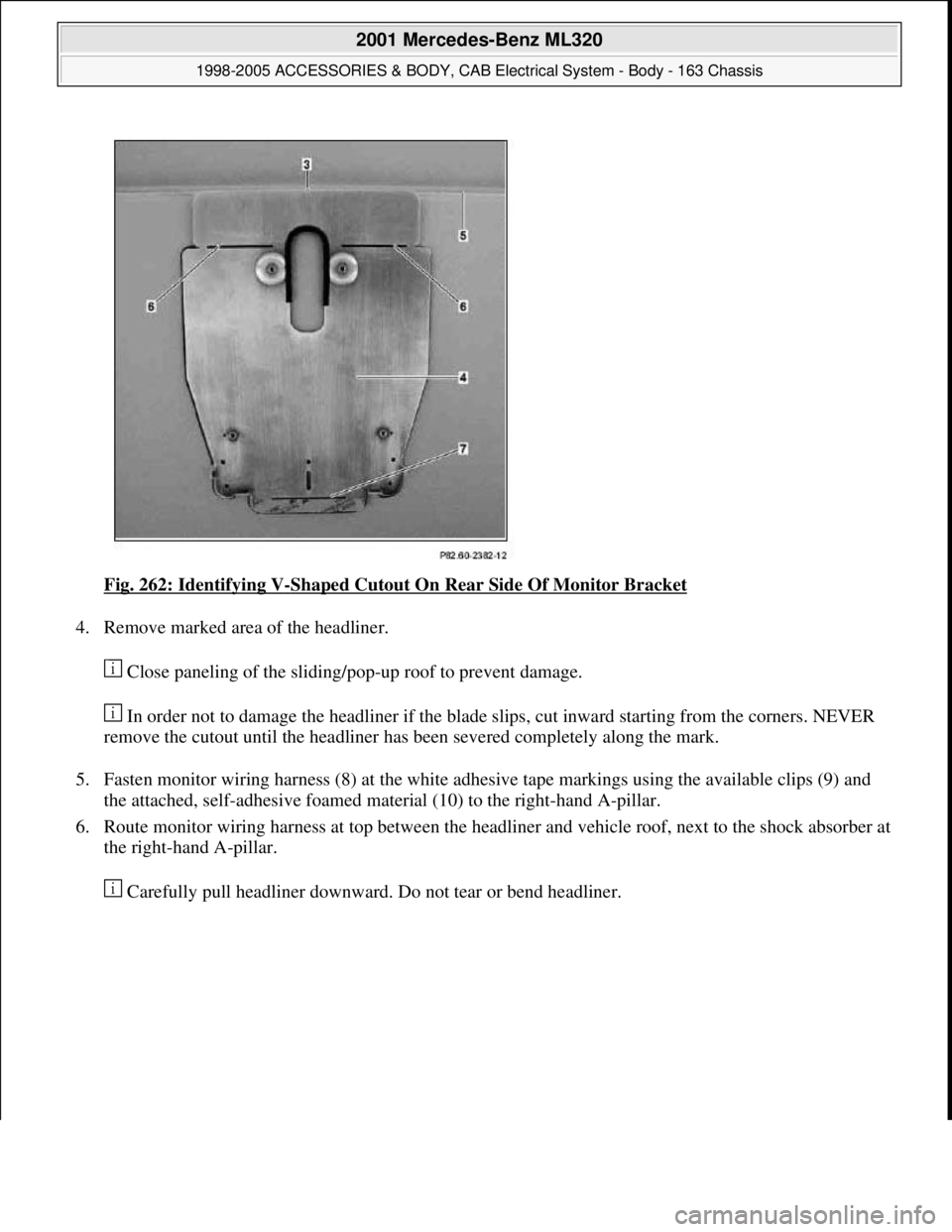
Fig. 262: Identifying V-Shaped Cutout On Rear Side Of Monitor Bracket
4. Remove marked area of the headliner.
Close paneling of the sliding/pop-up roof to prevent damage.
In order not to damage the headliner if the blade slips, cut inward starting from the corners. NEVER
remove the cutout until the headliner has been severed completely along the mark.
5. Fasten monitor wiring harness (8) at the white adhesive tape markings using the available clips (9) and
the attached, self-adhesive foamed material (10) to the right-hand A-pillar.
6. Route monitor wiring harness at top between the headliner and vehicle roof, next to the shock absorber at
the right-hand A-pillar.
Carefull
y pull headliner downward. Do not tear or bend headliner.
2001 Mercedes-Benz ML320
1998-2005 ACCESSORIES & BODY, CAB Electrical System - Body - 163 Chassis
me
Saturday, October 02, 2010 3:30:11 PMPage 353 © 2006 Mitchell Repair Information Company, LLC.
Page 1849 of 4133
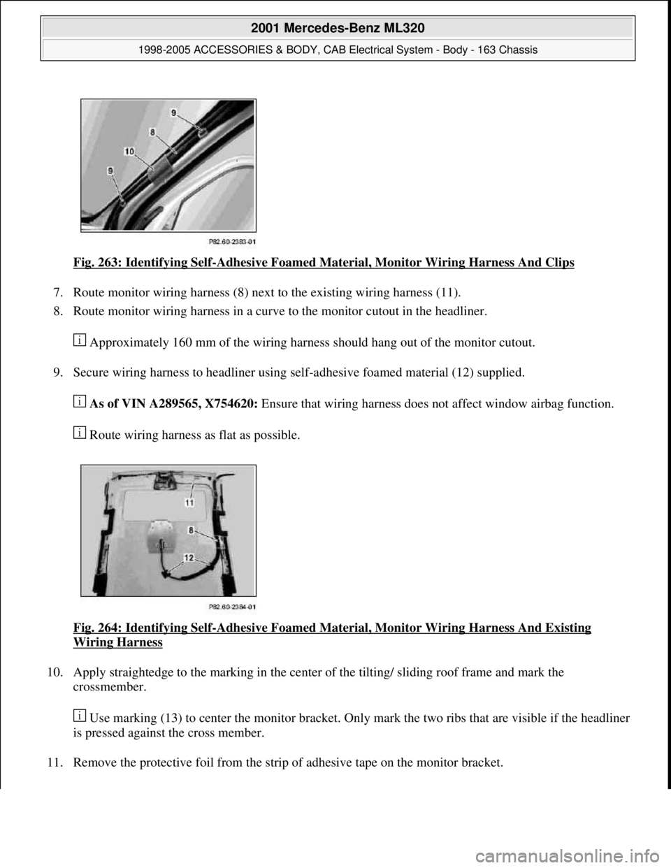
Fig. 263: Identifying Self-Adhesive Foamed Material, Monitor Wiring Harness And Clips
7. Route monitor wiring harness (8) next to the existing wiring harness (11).
8. Route monitor wiring harness in a curve to the monitor cutout in the headliner.
Approximately 160 mm of the wiring harness should hang out of the monitor cutout.
9. Secure wiring harness to headliner using self-adhesive foamed material (12) supplied.
As of VIN A289565, X754620: Ensure that wiring harness does not affect window airbag function.
Route wiring harness as flat as possible.
Fig. 264: Identifying Self
-Adhesive Foamed Material, Monitor Wiring Harness And Existing
Wiring Harness
10. Apply straightedge to the marking in the center of the tilting/ sliding roof frame and mark the
crossmember.
Use marking (13) to center the monitor bracket. Only mark the two ribs that are visible if the headliner
is pressed against the cross member.
11. Remove the protective foil from the strip of adhesive tape on the monitor bracket.
2001 Mercedes-Benz ML320
1998-2005 ACCESSORIES & BODY, CAB Electrical System - Body - 163 Chassis
me
Saturday, October 02, 2010 3:30:11 PMPage 354 © 2006 Mitchell Repair Information Company, LLC.
Page 1850 of 4133
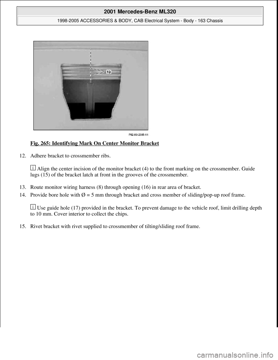
Fig. 265: Identifying Mark On Center Monitor Bracket
12. Adhere bracket to crossmember ribs.
Align the center incision of the monitor bracket (4) to the front marking on the crossmember. Guide
lugs (15) of the bracket latch at front in the grooves of the crossmember.
13. Route monitor wiring harness (8) through opening (16) in rear area of bracket.
14. Provide bore hole with Ø = 5 mm through bracket and cross member of sliding/pop-up roof frame.
Use guide hole (17) provided in the bracket. To prevent damage to the vehicle roof, limit drilling depth
to 10 mm. Cover interior to collect the chips.
15. Rivet bracket with rivet supplied to crossmember of tiltin
g/sliding roof frame.
2001 Mercedes-Benz ML320
1998-2005 ACCESSORIES & BODY, CAB Electrical System - Body - 163 Chassis
me
Saturday, October 02, 2010 3:30:11 PMPage 355 © 2006 Mitchell Repair Information Company, LLC.