instrument panel MERCEDES-BENZ ML500 1997 Complete Repair Manual
[x] Cancel search | Manufacturer: MERCEDES-BENZ, Model Year: 1997, Model line: ML500, Model: MERCEDES-BENZ ML500 1997Pages: 4133, PDF Size: 88.89 MB
Page 3204 of 4133

3
Remove engine hood hinge on the front
passenger side
AR88.40-P-3060GH
*BR00.45-Z-1004-01A
Danger!
Risk of explosion
from explosive gas.
Risk
of poisoning and caustic burns from
swallowing battery electrolyte.
Risk of injury
through burns to skin and eyes from battery
acid or when handling damaged lead-acid
batteries
No fire, sparks, naked flames or smoking.
Wear protective gloves, acid-resistant
clothing and safety glasses. Pour battery
electrolyte only into suitable and appropriately
marked containers.
AS54.10-Z-0001-01A
4
Remove battery
AR54.10-P-0005GH
5
Remove air conditioning blower motor
AR83.30-P-5560GH
6
Print out template (6) and adapt the size to
the correct dimensions (a, b)Determine ACTUAL dimension (a) from the
drawing.
Divide the SPECIFIED dimension (a) by the
determined ACTUAL dimension (a) and copy
the template to the original size with the
corresponding factor.
Check dimensions for both axles.
7
Cut out template
8
Cut out holes (7, 8) for engine hood hinge
studs
9
Position template in the engine hood hinge
support using the stud holes
The template is drawn for the left side.
Turn over to obtain the right side.
10
Center the engine hood hinge support on the
template using the markings (9, 10, 11)
11
Remove template
12
Drill a hole at each center punch mark (3, 4, 5)
Only drill through the 2 upper panels. Do
not drill through the reinforcement panel (3rd
panel).
*201589005100
13
Cover windshield, paint surface and adjacent
components adequately in order to avoid
damage due to welding work
Cover apertures in the body in order to
prevent flying sparks: the foam in the
instrument panel burns easily.
c
General information on repairs to body
AH60.00-N-0001-01A
Danger!
The high voltage used for arc welding
presents a lethal hazard
.
Explosion hazard
when welding in area of materials easily
inflammable.
Injury hazard
from welding
spatter and UV-light while welding.
Risk of
poisoning
when inhaling welding vapors.
Use insulating mats. Wear protective clothing,
safety glasses, and protective mask.
Remove
highly inflammable materials from the danger
zone. Use air extractor.
AS00.00-Z-0007-01A
14
Plug weld each hole
*WE58.40-Z-1005-02A
15
Plug welds should be flat and ground smooth
16
Remove covers and clean the repair area
17
Prime untreated points in the area of the
engine hood hinge support
18
Prime the underside of the reinforcement
panel of the engine hood hinge
Access to underside of engine hood hinge
support through the recess for the wiper motor.
19
Spray the underside of the reinforcement
panel of the engine hood hinge support with
wax preservative
Access to underside of engine hood hinge
support through the recess for the wiper motor.
20
Install in the reverse order
Weld spot miller
201 589 00 51 00
Workshop equipment/MB testers
(see Workshop Equipment Manual)
WE58.40-Z-1005-02A
MIG inert gas welding equipment, aluminum weldable, sold by company Wieländer & Schill
Repair products
Copyright DaimlerChrysler AG 09.05.2006 CD-Ausgabe G/10/04 . This WIS print-out will not be recorde
d by Modification services.
Page 2
Page 3214 of 4133
Mode control knob controls air distribution throughout the passenger compartment. Air distribution doors are
controlled by cables activated by the mode control knob. See Fig. 1
. Four mode positions are available with
detents in-between to adjust airflow for personal comfort.
Defrost
Set mode control knob to 12-o'clock position. Air will exit from defrost outlets and side window vents.
Vent
Set mode control knob to 9-o'clock position. Air will exit from instrument panel outlets.
Floor
Set mode control knob to 6-o'clock position. Air will exit from floor outlets.
Blend/Bi-Level
Set mode control knob to 3-o'clock position. Air will exit from defrost, instrument panel, and floor outlets.
TEMPERATURE CONTROL KNOB
Air temperature is controlled by a variable resistor rotary control switch. See Fig. 1 . Switch receives voltage
signal and depending upon position, controls voltage signal sent to air mix damper door motor. See Fig. 2
.
Volta
ge controls position of motor for heating and cooling.
2001 Mercedes-Benz ML320
2000-01 MANUAL A/C-HEATER SYSTEMS ML 320, ML 430 & ML 55
me
Saturday, October 02, 2010 3:25:10 PMPage 3 © 2006 Mitchell Repair Information Company, LLC.
Page 3216 of 4133
Fig. 2: Locating Climate Control Components
Courtesy of MERCEDES-BENZ OF NORTH AMERICA
FRESH/RECIRCULATION SWITCH
Fresh/recirculation switch controls voltage signal to fresh air recirculation door motor. See Fig. 1 and Fig. 2 .
With switch indicator light on, air will recirculate. With switch indicator light off, air will enter from outside of
vehicle.
A/C CONTROL MODULE
The A/C control module (A/C amplifier) is the control unit for the A/C system. See Fig. 2 . The module
receives inputs from various sensors and processes the information to control various outputs for the A/C
system for optimal control.
The A/C control module inputs are as follows:
A/C Switch
In-Vehicle Air Temperature Sensor
Temperature Selector Knob
Blower Motor Knob
Evaporator Temperature Sensor
Air Mix Damper Door Position Sensor
The A/C control module output functions are as follows:
Air Mix Damper Door Motor
All Activity Module
Fresh/Recirculation Door Motor
ALL ACTIVITY MODULE
All Activity Module (AAM) receives inputs to determine if specified conditions have been met to allow
operation of A/C-heater system. If conditions are met, the AAM will send signals to the A/C compressor,
condenser fans relay and the blower motor relay to command or enable operation.
IN-VEHICLE TEMPERATURE SENSOR
The in-vehicle temperature sensor is a negative temperature coefficient resistor. Sensor sends signals to the A/C
control module to maintain in-vehicle temperature. Sensor is located on the center panel of the instrument
cluster.
DUST FILTER
A dust filter provides filtering of air entering or recirculating in the passenger's compartment. The dust filter is
mounted between blower motor and evaporator, below passen
ger's side of instrument panel, to left of blower
2001 Mercedes-Benz ML320
2000-01 MANUAL A/C-HEATER SYSTEMS ML 320, ML 430 & ML 55
me
Saturday, October 02, 2010 3:25:10 PMPage 5 © 2006 Mitchell Repair Information Company, LLC.
Page 3226 of 4133
A/C EVAPORATOR HOUSING UNIT
Removal & Installation
1. Drain engine coolant. Remove coolant expansion reservoir nuts, disconnect hoses and remove reservoir.
Discharge A/C system, using approved refrigerant recovery/recycling equipment.
2. Remove expansion valve self-locking nut and discard. See Fig. 5
. Disconnect refrigerant lines from
expansion valve. Plug exposed refrigerant lines to protect A/C system from moisture and debris.
3. Remove instrument panel. See INSTRUMENT PANEL
. Remove Electronic Transmission Control
(ETC) module. See Fig. 4
. Disconnect air mix flap actuator connector.
4. Disconnect recirculated air flap element. Disconnect evaporator temperature sensor. Disconnect blower
motor resistor and blower motor connectors. Remove A/C push button control module. Release wiring
harness.
5. Remove insulating mat. See Fig. 5
. Disconnect water drain hose from bottom of A/C housing. Release
A/C housing-to-air distributor clips and remove A/C housing upward. To install, reverse removal
procedure. Recode radio. See RECODING RADIO
under PROGRAMMING. WARNING:To avoid injury from accidental air bag deployment, read and carefully
follow all SERVICE PRECAUTIONS and DISABLING & ACTIVATING AIR
BAG SYSTEM procedures in AIR BAG SYSTEM SAFETY article in
GENERAL SERVICING.
CAUTION: Before disconnecting battery, obtain 5-digit radio security code from
vehicle owner. Radio will be disabled until properly recoded.
2001 Mercedes-Benz ML320
2000-01 MANUAL A/C-HEATER SYSTEMS ML 320, ML 430 & ML 55
me
Saturday, October 02, 2010 3:25:10 PMPage 15 © 2006 Mitchell Repair Information Company, LLC.
Page 3227 of 4133
Fig. 4: Removing Evaporator Housing Unit
Courtesy of MERCEDES-BENZ OF NORTH AMERICA.
A/C MIX FLAP ACTUATOR
Removal & Installation
Remove instrument panel. See INSTRUMENT PANEL . Disconnect air mix flap actuator connector. Remove
3 screws and remove air mix flap actuator. To install reverse removal procedure.
A/C PUSH BUTTON CONTROL MODULE
Removal & Installation
Disconnect negative battery cable. Remove A/C push button control panel. See A/C PUSH BUTTON
CONTROL PANEL . Remove 4 A/C push button control module screws and remove control module from
2001 Mercedes-Benz ML320
2000-01 MANUAL A/C-HEATER SYSTEMS ML 320, ML 430 & ML 55
me
Saturday, October 02, 2010 3:25:10 PMPage 16 © 2006 Mitchell Repair Information Company, LLC.
Page 3228 of 4133
A/C housing. Disconnect control module connector. To install reverse removal procedure. Recode 5-digit radio
security code. Using HHT, check for DTC and erase, and set clock.
A/C PUSH BUTTON CONTROL PANEL
Removal & Installation
1. Obtain 5-digit radio security code from vehicle owner. Disconnect negative battery cable. Using radio
removal plates, remove radio. Disconnect electrical connectors.
2. Remove instrument panel center section. Remove 4 A/C control panel screws and remove control panel.
Release pull cables and disconnect connectors. To install, reverse removal procedure. Recode radio. See
RECODING RADIO
under PROGRAMMING.
BLOWER MOTOR
Removal & Installation
Remove passenger-side instrument panel under cover. Remove blower motor mounting screws from A/C
housing unit. Disconnect blower motor connector and remove blower motor. To install, reverse removal
procedure.
COMPRESSOR
Removal & Installation
1. Discharge A/C system, using approved refrigerant recovery/recycling equipment. Remove accessory
drive belt. Disconnect low pressure refrigerant line from compressor. Discard "O" rings. Plug exposed
openings to protect A/C system from debris and moisture.
2. Disconnect high pressure refrigerant line from compressor. Discard "O" rings. Plug exposed openings to
protect A/C system from debris and moisture. Disconnect electrical connector. Remove compressor
mounting bolts.
3. Raise and support vehicle. Remove compressor from under vehicle without spilling refrigerant oil. To
install, reverse removal procedure. Ensure refrigerant oil quantity in compressor is correct. See
COMPRESSOR REFRIGERANT OIL CHECKING under GENERAL SERVICING. Tighten bolts to
specification. See TORQUE SPECIFICATIONS
.
CONDENSER
Removal & Installation
1. Discharge A/C system, using approved refrigerant recovery/recycling equipment. Remove cooling fans.
See COOLING FANS
. Disconnect refrigerant line from receiver-drier. See Fig. 5 . Discard "O" rings.
2. Plug exposed openings to protect A/C system from debris and moisture. Remove refrigerant line from
condenser. Remove radiator upper rubber seal. See Fig. 6
. Remove condenser upper mounting screws.
Lift condenser upward and remove. NOTE: Each time A/C compressor is removed and installed, receiver-drier must be
replaced.
2001 Mercedes-Benz ML320
2000-01 MANUAL A/C-HEATER SYSTEMS ML 320, ML 430 & ML 55
me
Saturday, October 02, 2010 3:25:10 PMPage 17 © 2006 Mitchell Repair Information Company, LLC.
Page 3232 of 4133
Fig. 6: Removing Cooling Fans & Condenser
Courtesy of MERCEDES-BENZ OF NORTH AMERICA.
COOLING FANS
Removal & Installation
Remove headlight units. Remove upper frame crossmember, release hood release control cable and remove
crossmember. See Fig. 6
. Remove 2 cooling fans frame bolts on radiator. Disconnect cooling fan connector.
Release outside temperature sensor wiring harness. Pull up on cooling fan and remove. To install, reverse
removal procedure. Ensure cooling fan bottom guides are properly seated in lower mounts.
EVAPORATOR
Removal & Installation
Remove A/C housing unit. See A/C HOUSING UNIT . Remove expansion valve. See Fig. 5 . Discard "O"
rings. Disassemble A/C housing unit. Remove evaporator. Remove evaporator temperature sensor. To install,
reverse removal procedure. Use NEW "O" rings lubricated with refrigerant oil. If installing a new or repair
evaporator, add 1.35 ounces of NEW refrigerant oil to evaporator.
EXPANSION VALVE
Removal & Installation
1. Discharge A/C system, using approved refrigerant recovery/recycling equipment. Without disconnecting
coolant hoses, remove coolant expansion reservoir and set aside. Remove refrigerant line bracket and
loosen clamps. See Fig. 5
. Pull refrigerant lines out of expansion valve.
2. Remove expansion valve self-locking nut and discard. Remove expansion valve. Discard "O" rings. To
install, reverse removal procedure. Use NEW "O" rings lubricated with refrigerant oil. Tighten NEW self-
locking nut to specification. See TORQUE SPECIFICATIONS
.
INSTRUMENT PANEL & INSTRUMENT PANEL CARRIER
Removal & Installation
1. Secure vehicle against rolling. Set transmission selector to "D" position. Obtain radio security code.
Disconnect negative battery cable. Remove driver-side air bag.
2. Place match marks on steering wheel and steering shaft. Remove steering wheel, upper steering column
covers and combination switch. Remove instrument cluster cover frame. Remove one instrument panel
lower section bolt.
3. Remove screws in footwell from left side of instrument panel bottom section. Remove instrument panel
center section. Remove 4 A/C control panel screws and remove control panel. See Fig. 1
. Release pull
cables and disconnect connectors.
4. Remove screws from center section. Remove glove box. Remove screws in footwell from right side of
instrument panel bottom section. Remove entry courtesy lights. Remove end covers and screws.
5. Release 4 "A" clips between instrument panel bottom section and upper section. See Fig. 7
. Release
parkin
g brake release cable from handle. With assistance, remove instrument panel bottom section.
2001 Mercedes-Benz ML320
2000-01 MANUAL A/C-HEATER SYSTEMS ML 320, ML 430 & ML 55
me
Saturday, October 02, 2010 3:25:10 PMPage 21 © 2006 Mitchell Repair Information Company, LLC.
Page 3233 of 4133
6. Remove A-pillar panel trim. Remove instrument cluster. Remove defroster vent cover. Remove air vents
and side air nozzles. With assistance, remove upper instrument panel.
7. Remove passenger-side air bag. Remove right side lower instrument panel cover. Remove instrument
panel carrier screws from A/C housing unit. Remove left side lower instrument panel cover.
8. Remove insulating mat between steering column and instrument panel carrier. Remove steering column
bolts and nuts from instrument panel carrier. See Fig. 8
. Remove instrument panel carrier center tunnel
bolts. Disconnect steering column connectors.
9. Remove wiring harness from instrument panel carrier. Remove wiper washer system. Remove instrument
panel carrier nuts from engine compartment side of firewall.
10. Remove A-pillar bolt covers and remove instrument panel carrier A-pillar bolts. With assistance, remove
instrument panel carrier through passenger door. To install, reverse removal procedure.
11. Ensure instrument panel bottom section guide tongues "B" are seated into instrument panel upper section
mounts. See Fig. 8
. Tighten nuts and bolts to specification. See TORQUE SPECIFICATIONS .
Recode radio. See RECODING RADIO
under PROGRAMMING.
Fig. 7: Removing Instrument Panel Bottom Section
Courtesy of MERCEDES-BENZ OF NORTH AMERICA.
2001 Mercedes-Benz ML320
2000-01 MANUAL A/C-HEATER SYSTEMS ML 320, ML 430 & ML 55
me
Saturday, October 02, 2010 3:25:10 PMPage 22 © 2006 Mitchell Repair Information Company, LLC.
Page 3234 of 4133
Fig. 8: Removing Instrument Panel Upper Section & Instrument Panel Carrier
Courtesy of MERCEDES-BENZ OF NORTH AMERICA.
INTAKE AIR DUST FILTER
Removal & Installation
Remove passenger-side instrument panel lower trim panel. Release retaining clip and remove dust filter cover.
Pull dust filter down and out. See Fig. 9
. To install, reverse removal procedure.
2001 Mercedes-Benz ML320
2000-01 MANUAL A/C-HEATER SYSTEMS ML 320, ML 430 & ML 55
me
Saturday, October 02, 2010 3:25:10 PMPage 23 © 2006 Mitchell Repair Information Company, LLC.
Page 3254 of 4133
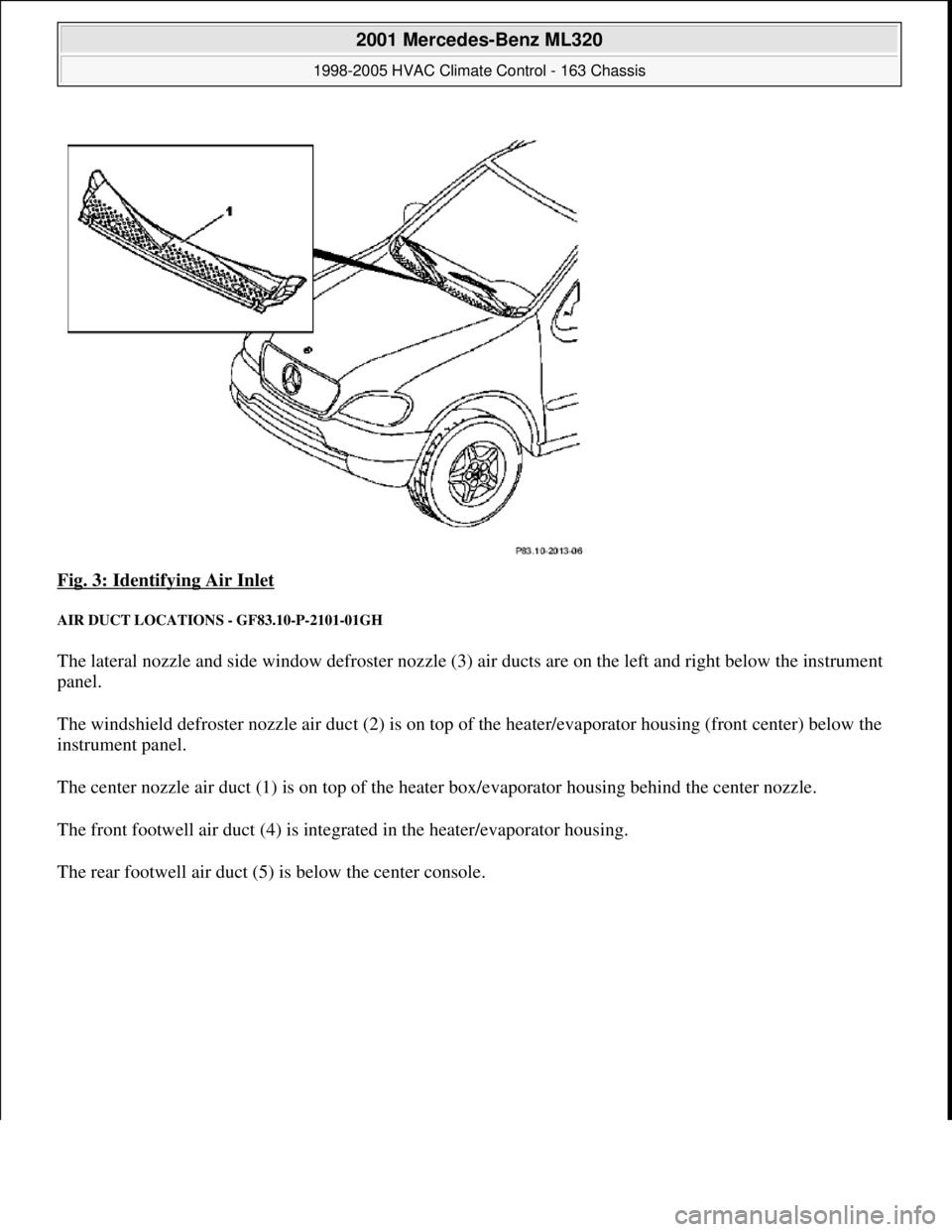
Fig. 3: Identifying Air Inlet
AIR DUCT LOCATIONS - GF83.10-P-2101-01GH
The lateral nozzle and side window defroster nozzle (3) air ducts are on the left and right below the instrument
panel.
The windshield defroster nozzle air duct (2) is on top of the heater/evaporator housing (front center) below the
instrument panel.
The center nozzle air duct (1) is on top of the heater box/evaporator housing behind the center nozzle.
The front footwell air duct (4) is integrated in the heater/evaporator housing.
The rear footwell air duct (5) is below the center console.
2001 Mercedes-Benz ML320
1998-2005 HVAC Climate Control - 163 Chassis
me
Saturday, October 02, 2010 3:23:14 PMPage 10 © 2006 Mitchell Repair Information Company, LLC.