instrument panel MERCEDES-BENZ ML500 1997 Complete Repair Manual
[x] Cancel search | Manufacturer: MERCEDES-BENZ, Model Year: 1997, Model line: ML500, Model: MERCEDES-BENZ ML500 1997Pages: 4133, PDF Size: 88.89 MB
Page 3255 of 4133

Fig. 4: Identifying Air Duct (Up To 31.08.01)
AIR DUCT LOCATIONS - GF83.10-P-2101-01GI
The lateral nozzle and side window defroster nozzle (3) air ducts are on the left and right below the instrument
panel.
The windshield defroster nozzle air duct (2) is on top of the evaporator housing (front center) below the
instrument panel.
The center nozzle air duct (1) is on top of the evaporator housing behind the center nozzle.
The front footwell air duct (4) is integrated in the heater/evaporator housing.
The rear compartment air duct (5) is located below the center console.
The rear footwell air duct (6) is at the bottom next to the rear blower behind the center console.
2001 Mercedes-Benz ML320
1998-2005 HVAC Climate Control - 163 Chassis
me
Saturday, October 02, 2010 3:23:14 PMPage 11 © 2006 Mitchell Repair Information Company, LLC.
Page 3256 of 4133

Fig. 5: Identifying Air Duct (As Of 1.09.01)
BLOWER, LOCATION - GF83.10-P-2102-01GH
The blower (M2) is below the instrument panel to th e bottom right of the heater box/evaporator housing (3).
2001 Mercedes-Benz ML320
1998-2005 HVAC Climate Control - 163 Chassis
me
Saturday, October 02, 2010 3:23:14 PMPage 12 © 2006 Mitchell Repair Information Company, LLC.
Page 3258 of 4133

The blower regulator then controls the blower motor operating voltage, depending on the actual measured in-car
temperature and the selected target temperature
(0-12 V). This facilitates blower speed control of 0-100 %.
DUST FILTER, LOCATION - GF83.10-P-2104-01GH
The dust filter (1) is behind the instrument panel bottom section at the passenger side in the heater/evaporator
housing.
Fig. 7: Identifying Dust Filter
REAR VENTILATION, FUNCTION - GF83.10-P-2105-01GC
Function
The louvered-type flaps in the rear vent open from the pressure of the air flowing through the vehicle and allow
it to exit.
If a vacuum is present in the vehicle, as happens when driving with a window or the sliding roof open, the flaps
close automatically due to the force of gravity. This prevents exhaust gases, dust and moisture from being
sucked in.
REAR VENTILATION, LOCATION - GF83.10-P-2105-02GH
The rear vents (1) are located on the left and right behind the rear bumper.
2001 Mercedes-Benz ML320
1998-2005 HVAC Climate Control - 163 Chassis
me
Saturday, October 02, 2010 3:23:14 PMPage 14 © 2006 Mitchell Repair Information Company, LLC.
Page 3259 of 4133

Fig. 8: Identifying Rear Vents
DEFROSTER NOZZLE, LOCATION - GF83.10-P-2106-01GH
Windshield defroster nozzle
The windshield defroster nozzle (1) is located in the instrument panel below the windshield.
Fig. 9: Identifying Windshield Defroster Nozzle
Side window defroster nozzles
The side window defroster nozzles (1) are located on the left and ri
ght in the instrument panel.
2001 Mercedes-Benz ML320
1998-2005 HVAC Climate Control - 163 Chassis
me
Saturday, October 02, 2010 3:23:14 PMPage 15 © 2006 Mitchell Repair Information Company, LLC.
Page 3261 of 4133

CENTER NOZZLE, LOCA TION - GF83.10-P-2107-02GH
The center nozzle (1) is located above the center console in the instrument panel.
Fig. 12: Identifying Center Nozzle
SIDE NOZZLE, FUNCTI ON - GF83.10-P-2108-01GH
Function
The side nozzle (3) can be adjusted infinitely or opened and closed completely with the dial.
The air exit direction can be adjusted upward, downward, to the left, to the right or middle as desired with the
louver system.
Heated/cooled air exits th rough the side nozzle (3).
Fig. 13: Identifying Side Nozzle
SIDE NOZZLE, LOCATI ON - GF83.10-P-2108-02GH
2001 Mercedes-Benz ML320
1998-2005 HVAC Climate Control - 163 Chassis
me
Saturday, October 02, 2010 3:23:14 PMPage 17 © 2006 Mitchell Repair Information Company, LLC.
Page 3262 of 4133

The side nozzles (3) are located at the outside left and right in the instrument panel.
Fig. 14: Identifying Side Nozzle
FRONT FOOTWELL AIR VENT FUNCTION - GF83.10-P-2109-01GC
Function up to 31.08.01
The air supply to the front footwell air vents can be opened and closed via the air distribution switch using a
cable.
There is no separate adjusting facility. Temperature-controlled air comes out of the front footwell air vents.
Function as of 1.09.01
The air supply to the front footwell air vents can be opened and closed via the air distribution switch with the
footwell flap actuator motor.
There is no separate adjusting facility. Temperature-controlled air comes out of the front footwell air vents.
FRONT FOOTWELL AIR OUTLET, LOCATION - GF83.10-P-2109-02GH
The front footwell air outlet (4) (driver's side) is installed in the lower section of the instrument panel.
The front footwell air outlet (passen
ger's side) is integrated into the heater/A/C housing.
2001 Mercedes-Benz ML320
1998-2005 HVAC Climate Control - 163 Chassis
me
Saturday, October 02, 2010 3:23:15 PMPage 18 © 2006 Mitchell Repair Information Company, LLC.
Page 3266 of 4133

Fig. 18: Identifying Recirculating Air Switch
RECIRCULATING AIR SWITCH LOCATION/TASK/DESIGN/FUNCTION - GF83.10-P-2117GH
MODEL 163 up to 31.8.01
SERIES RESISTOR GROUP, POSITION - GF83.10-P-2124-01GH
The series resistor group (R14) is at the bottom right of the heater/ evaporator housing (1) behind the bottom
section of the instrument panel at the passenger side (2).
Fig. 19: Identifying Series Resistor Group
SERIES RESISTOR ASSEMBLY FUNCTION - GF83.10-P-2124-02GH
Function
Recirculating air switch
location GF83.10-P-2117-
02GH
Recirculating air switch,
taskThe recirculating air switch ( ) is used to operate the
fresh air/recirculating air flap.
Recirculating air switch,
designThe recirculating air switch ( ) is equipped with an LED
as a malfunction indicator lamp.
Recirculating air switch
function GF83.10-P-2117-
01GH
2001 Mercedes-Benz ML320
1998-2005 HVAC Climate Control - 163 Chassis
me
Saturday, October 02, 2010 3:23:15 PMPage 22 © 2006 Mitchell Repair Information Company, LLC.
Page 3281 of 4133

Fig. 29: Locating Center Outlet Flap Actuator Motor
REAR AIR DISTRIBUTION FLAP ACTUATOR MOTOR FUNCTION - GF83.10-P-2173-01GI
Function
Pressing the rear compartment air distribution button ( ) on the AAC push-button control module (N22)
actuates the air distribution flap actuator motor (M2/21) via the AC bus. The air distribution flap actuator motor
(M2/21) therefore controls the air distribution flap, which opens and controls the air supply to the rear blowout
ducts.
If a problem exists, it is possible to retrieve and verify the defined end positions by means of the Diagnosis
Assistant System (DAS) (valuation trip).
After replacing an actuator motor an adjustment run must be performed using the Diagnosis Assistant System
Center outlet flap
actuator motor locationThe center outlet flap actuator motor (M2/22) is to the right of
the center nozzle air duct, below the instrument panel.
Center outlet flap
actuator motor taskThe center outlet flap actuator motor (M2/22) operates the
center outlet flap for controlling the flow of air to the center
nozzle.
Center outlet flap
actuator motor function GF83.10-P-
2172-01GI
NOTE: All actuator motors are identical.
2001 Mercedes-Benz ML320
1998-2005 HVAC Climate Control - 163 Chassis
me
Saturday, October 02, 2010 3:23:15 PMPage 37 © 2006 Mitchell Repair Information Company, LLC.
Page 3288 of 4133
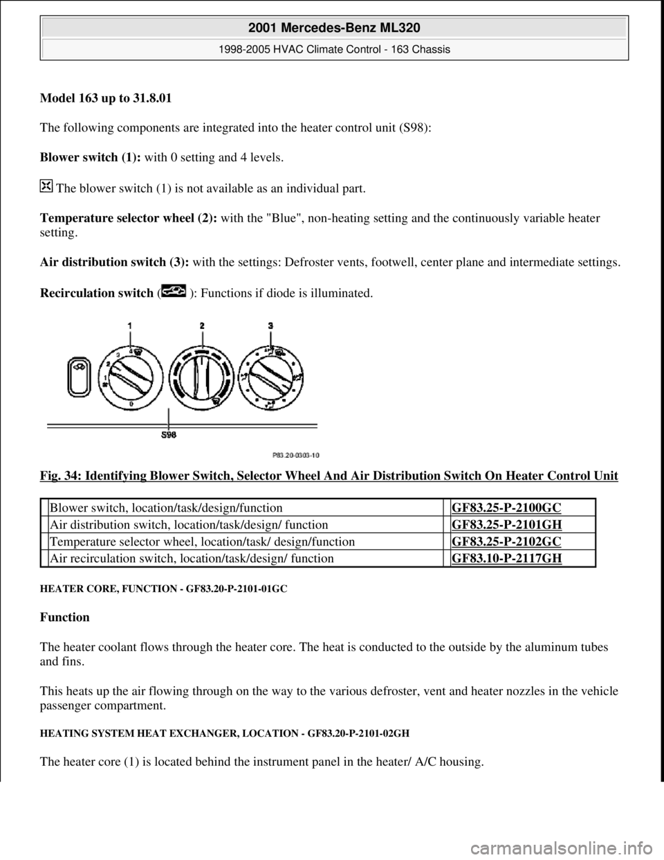
Model 163 up to 31.8.01
The following components are integrated into the heater control unit (S98):
Blower switch (1): with 0 setting and 4 levels.
The blower switch (1) is not available as an individual part.
Temperature selector wheel (2): with the "Blue", non-heating setting and the continuously variable heater
setting.
Air distribution switch (3): with the settings: Defroster vents, footwe ll, center plane and intermediate settings.
Recirculation switch ( ): Functions if diode is illuminated.
Fig. 34: Identifying Blower Switch, Selector Wheel And Air Distribution Switch On Heater Control Unit
HEATER CORE, FUNCTI ON - GF83.20-P-2101-01GC
Function
The heater coolant flows through the heater core. The he at is conducted to the outside by the aluminum tubes
and fins.
This heats up the air flowing through on the way to the vari ous defroster, vent and heater nozzles in the vehicle
passenger compartment.
HEATING SYSTEM HEAT EXCHANGE R, LOCATION - GF83.20-P-2101-02GH
The heater core (1) is located behind the instrument panel in the heater/ A/C housing.
Blower switch, location/task/design/function GF83.25-P-2100GC
Air distribution switch, locat ion/task/design/ function GF83.25-P-2101GH
Temperature selector wheel, location/task/ design/function GF83.25-P-2102GC
Air recirculation switch, loca tion/task/design/ function GF83.10-P-2117GH
2001 Mercedes-Benz ML320
1998-2005 HVAC Climate Control - 163 Chassis
me
Saturday, October 02, 2010 3:23:15 PMPage 44 © 2006 Mitchell Repair Information Company, LLC.
Page 3290 of 4133
The heating water circulation pump runs in any event 1 minute after starting residual engine heat operation. The
overshoot conditions at least will be fulfilled.
Overshoot conditions
Coolant temperature 100°C --> overshoot time 5 minutes
Coolant temperature >100°C --> overshoot time 10 minutes
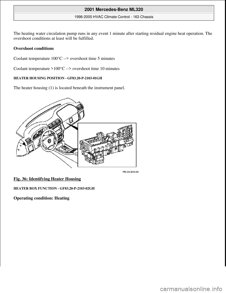
HEATER HOUSING POSITION - GF83.20-P-2103-01GH
The heater housing (1) is located beneath the instrument panel.
Fig. 36: Identifying Heater Housing
HEATER BOX FUNCTION - GF83.20-P-2103-02GH
Operating condition: Heating
2001 Mercedes-Benz ML320
1998-2005 HVAC Climate Control - 163 Chassis
me
Saturday, October 02, 2010 3:23:15 PMPage 46 © 2006 Mitchell Repair Information Company, LLC.