check engine MERCEDES-BENZ ML500 1997 Complete Repair Manual
[x] Cancel search | Manufacturer: MERCEDES-BENZ, Model Year: 1997, Model line: ML500, Model: MERCEDES-BENZ ML500 1997Pages: 4133, PDF Size: 88.89 MB
Page 3220 of 4133
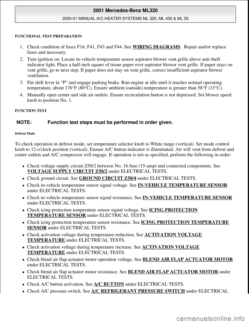
FUNCTIONAL TEST PREPARATION
1. Check condition of fuses F16, F41, F43 and F44. See WIRING DIAGRAMS . Repair and/or replace
fuses and necessary.
2. Turn ignition on. Locate in-vehicle temperature sensor aspirator blower vent grille above anti-theft
indicator light. Place a half-inch square of tissue paper over aspirator blower vent grille. If paper stays on
vent grille, go to next step. If paper does not stay on vent grille, correct insufficient aspirator blower
ventilation.
3. Put shift lever in "P" and engage parking brake. Run engine at idle until it reaches normal operating
temperature, about 176°F (80°C). Ensure ambient (outside) temperature is greater than 58°F (15°C).
4. Manually open center and side air outlets. Ensure recirculation button is not depressed. Set blower speed
knob to position No. 1.
FUNCTION TEST
Defrost Mode
To check operation in defrost mode, set temperature selector knob to White range (vertical). Set mode control
knob to 12-o'clock position (vertical). Ensure A/C button indicator is illuminated. Air will vent from defrost and
center outlets and A/C compressor will engage. If operation is not as specified, perform the following in order:
Check voltage supply circuit Z50/2 between No. 16 fuse (15-amp) and connected components. See
VOLTAGE SUPPLY CIRCUIT Z50/2
under ELECTRICAL TESTS.
Check ground circuit. See GROUND CIRCUIT Z50/4 under ELECTRICAL TESTS.
Check in-vehicle temperature sensor signal voltage. See IN-VEHICLE TEMPERATURE SENSOR
under ELECTRICAL TESTS.
Check in-vehicle temperature sensor signal resistance. See IN-VEHICLE TEMPERATURE SENSOR
under ELECTRICAL TESTS.
Check icing protection temperature sensor signal voltage. See ICING PROTECTION
TEMPERATURE SENSOR under ELECTRICAL TESTS.
Check icing protection temperature sensor resistance. See ICING PROTECTION TEMPERATURE
SENSOR under ELECTRICAL TESTS.
Check activation voltage during temperature reduction. See ACTIVATION VOLTAGE
TEMPERATURE under ELECTRICAL TESTS.
Check activation voltage during temperature increase. See ACTIVATION VOLTAGE
TEMPERATURE under ELECTRICAL TESTS.
Check blend air flap actuator motor operation voltage. See BLEND AIR FLAP ACTUATOR MOTOR
under ELECTRICAL TESTS.
Check blend air flap actuator motor resistance. See BLEND AIR FLAP ACTUATOR MOTOR under
ELECTRICAL TESTS.
Check A/C button activation. See A/C BUTTON under ELECTRICAL TESTS.
Check A/C pressure switch. See A/C REFRIGERANT PRESSURE SWITCH under ELECTRICAL NOTE: Function test steps must be performed in order given.
2001 Mercedes-Benz ML320
2000-01 MANUAL A/C-HEATER SYSTEMS ML 320, ML 430 & ML 55
me
Saturday, October 02, 2010 3:25:10 PMPage 9 © 2006 Mitchell Repair Information Company, LLC.
Page 3221 of 4133
TESTS.
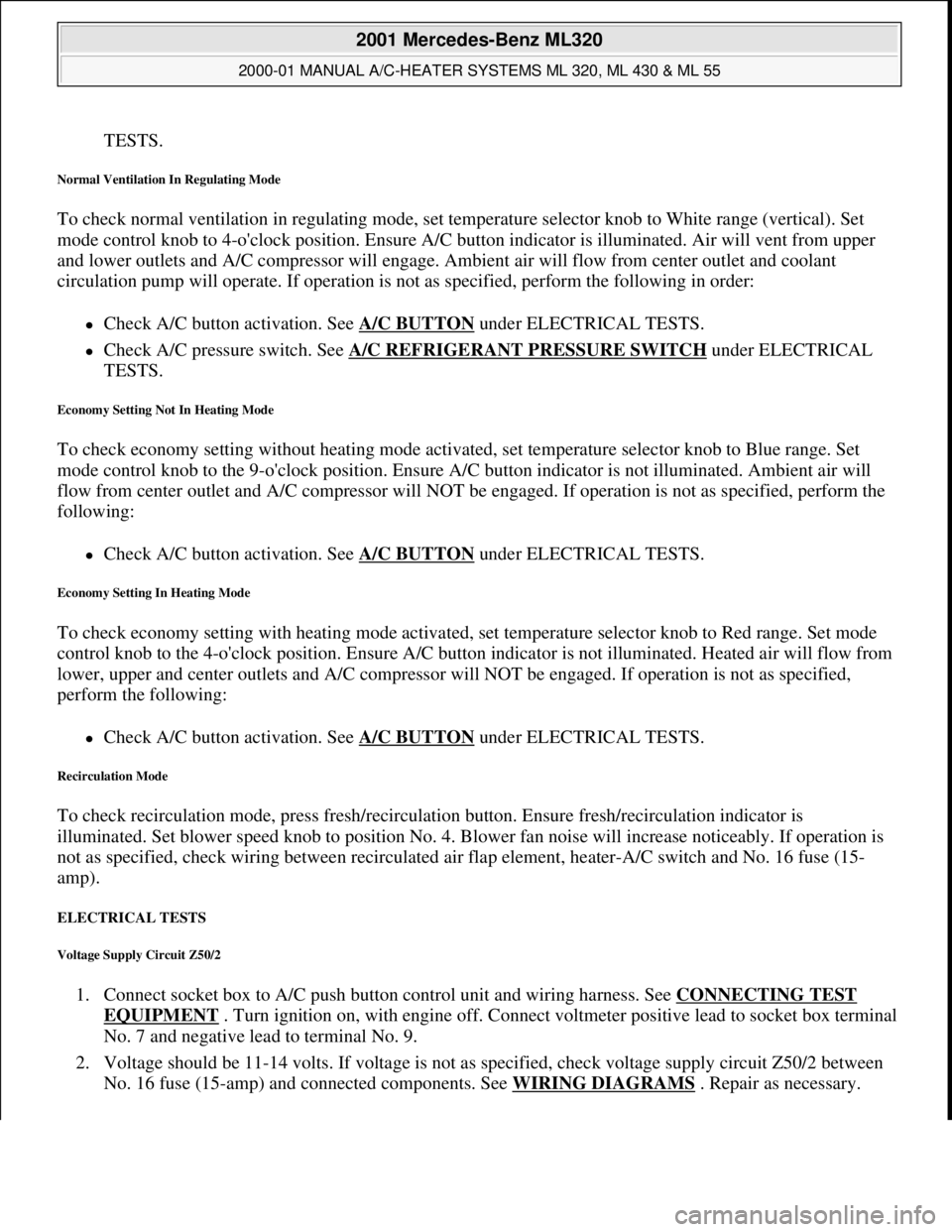
Normal Ventilation In Regulating Mode
To check normal ventilation in regulating mode, set temperature selector knob to White range (vertical). Set
mode control knob to 4-o'clock position. Ensure A/C button indicator is illuminated. Air will vent from upper
and lower outlets and A/C compressor will engage. Ambient air will flow from center outlet and coolant
circulation pump will operate. If operation is not as specified, perform the following in order:
Check A/C button activation. See A/C BUTTON under ELECTRICAL TESTS.
Check A/C pressure switch. See A/C REFRIGERANT PRESSURE SWITCH under ELECTRICAL
TESTS.
Economy Setting Not In Heating Mode
To check economy setting without heating mode activated, set temperature selector knob to Blue range. Set
mode control knob to the 9-o'clock position. Ensure A/C button indicator is not illuminated. Ambient air will
flow from center outlet and A/C compressor will NOT be engaged. If operation is not as specified, perform the
following:
Check A/C button activation. See A/C BUTTON under ELECTRICAL TESTS.
Economy Setting In Heating Mode
To check economy setting with heating mode activated, set temperature selector knob to Red range. Set mode
control knob to the 4-o'clock position. Ensure A/C button indicator is not illuminated. Heated air will flow from
lower, upper and center outlets and A/C compressor will NOT be engaged. If operation is not as specified,
perform the following:
Check A/C button activation. See A/C BUTTON under ELECTRICAL TESTS.
Recirculation Mode
To check recirculation mode, press fresh/recirculation button. Ensure fresh/recirculation indicator is
illuminated. Set blower speed knob to position No. 4. Blower fan noise will increase noticeably. If operation is
not as specified, check wiring between recirculated air flap element, heater-A/C switch and No. 16 fuse (15-
amp).
ELECTRICAL TESTS
Voltage Supply Circuit Z50/2
1. Connect socket box to A/C push button control unit and wiring harness. See CONNECTING TEST
EQUIPMENT . Turn ignition on, with engine off. Connect voltmeter positive lead to socket box terminal
No. 7 and negative lead to terminal No. 9.
2. Voltage should be 11-14 volts. If voltage is not as specified, check voltage supply circuit Z50/2 between
No. 16 fuse (15-amp) and connected components. See WIRING DIAGRAMS
. Repair as necessary.
2001 Mercedes-Benz ML320
2000-01 MANUAL A/C-HEATER SYSTEMS ML 320, ML 430 & ML 55
me
Saturday, October 02, 2010 3:25:10 PMPage 10 © 2006 Mitchell Repair Information Company, LLC.
Page 3225 of 4133
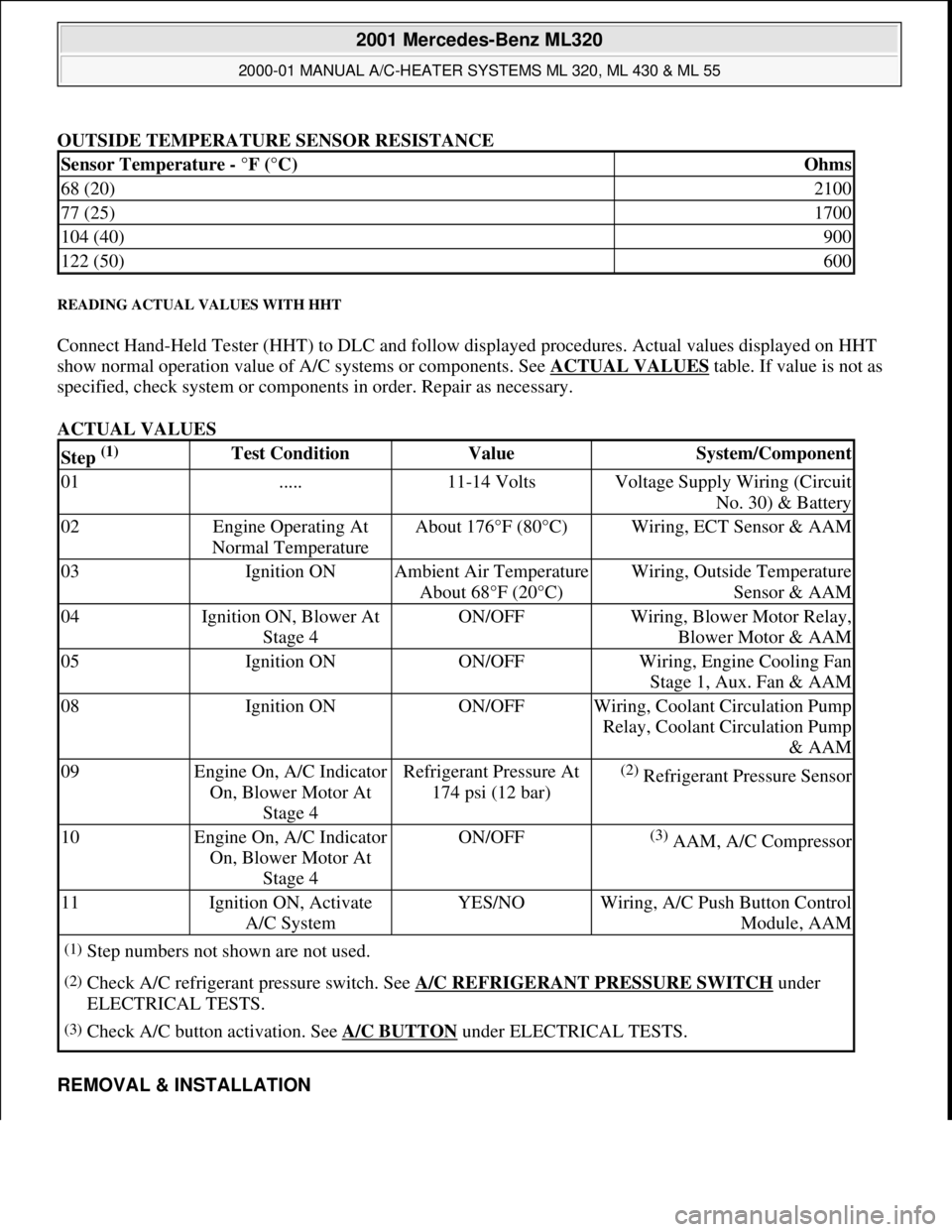
OUTSIDE TEMPERATURE SENSOR RESISTANCE
READING ACTUAL VALUES WITH HHT
Connect Hand-Held Tester (HHT) to DLC and follow displayed procedures. Actual values displayed on HHT
show normal operation value of A/C systems or components. See ACTUAL VALUES
table. If value is not as
specified, check system or components in order. Repair as necessary.
ACTUAL VALUES
REMOVAL & INSTALLATION
Sensor Temperature - °F (°C)Ohms
68 (20)2100
77 (25)1700
104 (40)900
122 (50)600
Step (1) Test ConditionValueSystem/Component
01.....11-14 VoltsVoltage Supply Wiring (Circuit
No. 30) & Battery
02Engine Operating At
Normal TemperatureAbout 176°F (80°C)Wiring, ECT Sensor & AAM
03Ignition ONAmbient Air Temperature
About 68°F (20°C)Wiring, Outside Temperature
Sensor & AAM
04Ignition ON, Blower At
Stage 4ON/OFFWiring, Blower Motor Relay,
Blower Motor & AAM
05Ignition ONON/OFFWiring, Engine Cooling Fan
Stage 1, Aux. Fan & AAM
08Ignition ONON/OFFWiring, Coolant Circulation Pump
Relay, Coolant Circulation Pump
& AAM
09Engine On, A/C Indicator
On, Blower Motor At
Stage 4Refrigerant Pressure At
174 psi (12 bar)(2) Refrigerant Pressure Sensor
10Engine On, A/C Indicator
On, Blower Motor At
Stage 4ON/OFF(3) AAM, A/C Compressor
11Ignition ON, Activate
A/C SystemYES/NOWiring, A/C Push Button Control
Module, AAM
(1)Step numbers not shown are not used.
(2)Check A/C refrigerant pressure switch. See A/C REFRIGERANT PRESSURE SWITCH under
ELECTRICAL TESTS.
(3)Check A/C button activation. See A/C BUTTON under ELECTRICAL TESTS.
2001 Mercedes-Benz ML320
2000-01 MANUAL A/C-HEATER SYSTEMS ML 320, ML 430 & ML 55
me
Saturday, October 02, 2010 3:25:10 PMPage 14 © 2006 Mitchell Repair Information Company, LLC.
Page 3311 of 4133
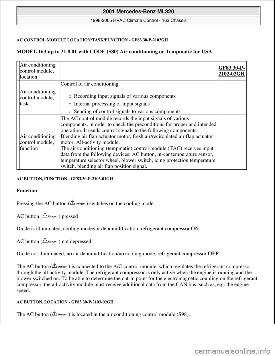
AC CONTROL MODULE LOCATION/TASK/FUNCTION - GF83.30-P-2102GH
MODEL 163 up to 31.8.01 with CODE (580) Air conditioning or Tempmatic for USA
AC BUTTON, FUNCTION - GF83.30-P-2103-01GH
Function
Pressing the AC button ( ) switches on the cooling mode.
AC button ( ) pressed
Diode is illuminated, cooling mode/air dehumidification, refrigerant compressor ON
AC button ( ) not depressed
Diode not illuminated, no air dehumidification/no cooling mode, refrigerant compressor OFF
The AC button ( ) is connected to the A/C control module, which regulates the refrigerant compressor
through the all-activity module. The refrigerant compressor is only active when the engine is running and the
blower switched on. To be able to determine the cut-in point for the electromagnetic coupling on the refrigerant
compressor, the all-activity module must receive additional data from the CAN bus, such as, e.g. the engine
speed.
AC BUTTON, LOCATION - GF83.30-P-2103-02GH
The AC button ( ) is located in the air conditioning control module (S98).
Air conditioning
control module,
location
GF83.30-P-
2102-02GH
Air conditioning
control module,
task
Control of air conditioning
Recording input signals of various components
Internal processing of input signals
Sending of control signals to various components
Air conditioning
control module,
function
The AC control module records the input signals of various
components, in order to check the preconditions for proper and intended
operation. It sends control signals to the following components:
Blending air flap actuator motor, fresh air/recirculated air flap actuator
motor, All-activity module.
The air conditioning (tempmatic) control module (TAC) receives input
data from the following devices: AC button, in-car temperature sensor,
temperature selector wheel, blower switch, icing protection temperature
switch, blending air flap position signal.
2001 Mercedes-Benz ML320
1998-2005 HVAC Climate Control - 163 Chassis
me
Saturday, October 02, 2010 3:23:15 PMPage 67 © 2006 Mitchell Repair Information Company, LLC.
Page 3404 of 4133
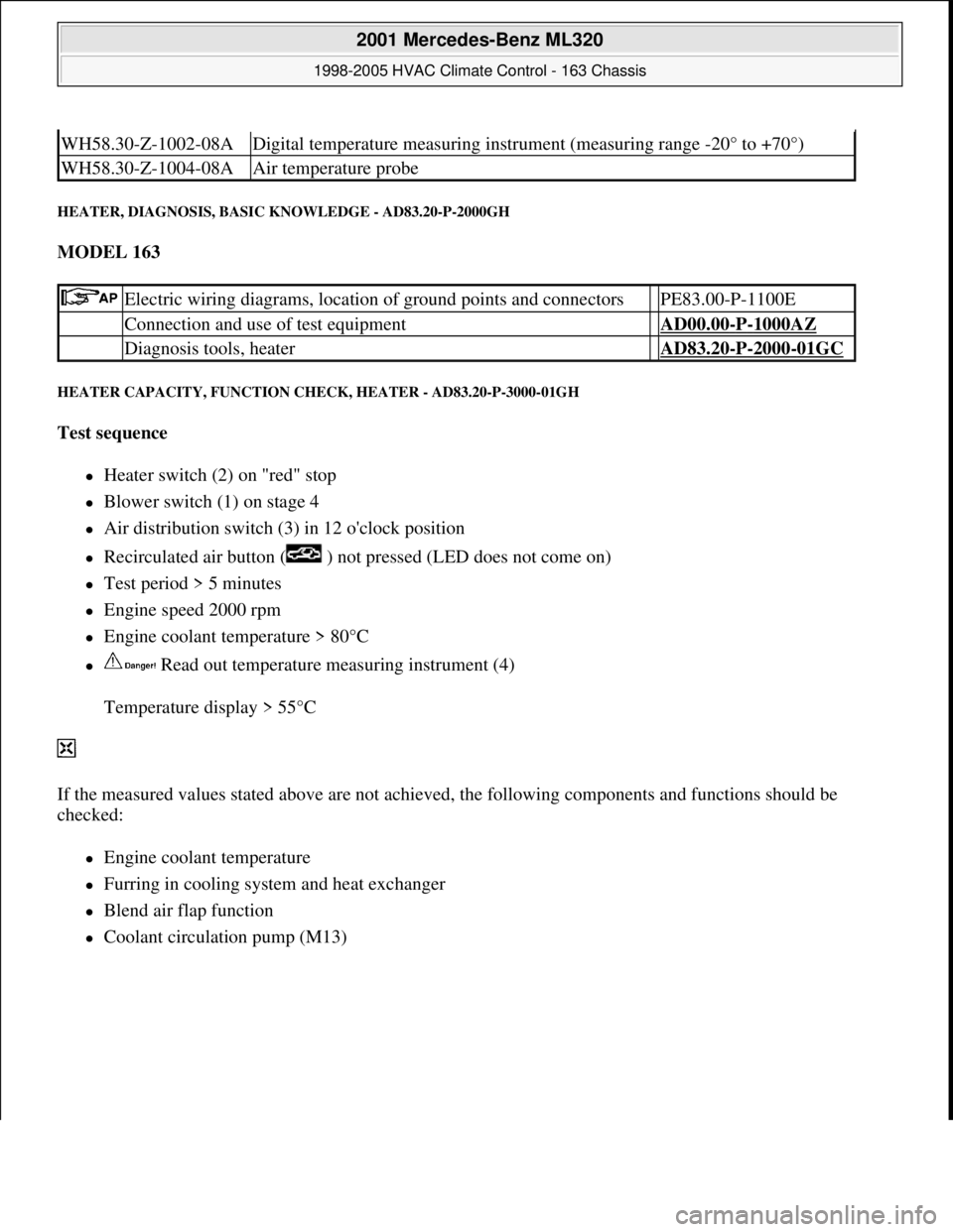
HEATER, DIAGNOSIS, BASIC KNOWLEDGE - AD83.20-P-2000GH
MODEL 163
HEATER CAPACITY, FUNCTION CHECK, HEATER - AD83.20-P-3000-01GH
Test sequence
Heater switch (2) on "red" stop
Blower switch (1) on stage 4
Air distribution switch (3) in 12 o'clock position
Recirculated air button ( ) not pressed (LED does not come on)
Test period > 5 minutes
Engine speed 2000 rpm
Engine coolant temperature > 80°C
Read out temperature measuring instrument (4)
Temperature display > 55°C
If the measured values stated above are not achieved, the following components and functions should be
checked:
Engine coolant temperature
Furring in cooling system and heat exchanger
Blend air flap function
Coolant circulation pump (M13)
WH58.30-Z-1002-08ADigital temperature measuring instrument (measuring range -20° to +70°)
WH58.30-Z-1004-08AAir temperature probe
Electric wiring diagrams, location of ground points and connectors PE83.00-P-1100E
Connection and use of test equipment AD00.00-P-1000AZ
Diagnosis tools, heater AD83.20-P-2000-01GC
2001 Mercedes-Benz ML320
1998-2005 HVAC Climate Control - 163 Chassis
me
Saturday, October 02, 2010 3:23:17 PMPage 160 © 2006 Mitchell Repair Information Company, LLC.
Page 3405 of 4133
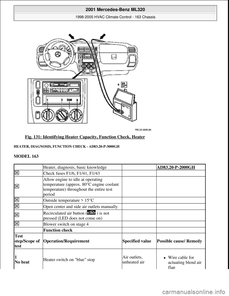
Fig. 131: Identifying Heater Capacity, Function Check, Heater
HEATER, DIAGNOSIS, FUNCTION CHECK - AD83.20-P-3000GH
MODEL 163
Heater, diagnosis, basic knowledge AD83.20-P-2000GH
Check fuses F1/6, F1/41, F1/43
Allow engine to idle at operating
temperature (approx. 80°C engine coolant
temperature) throughout the entire test
period
Outside temperature > 15°C
Open center and side air outlets manually
Recirculated air button ( ) is not
pressed (LED does not come on)
Blower switch on stage 4
Function check
Test
step/Scope of
test
Operation/Requirement Specified value Possible cause/ Remedy
1
No heat Heater switch on "blue" stopAir outlets,
unheated airWire cable for
actuating blend air
flap
2001 Mercedes-Benz ML320
1998-2005 HVAC Climate Control - 163 Chassis
me
Saturday, October 02, 2010 3:23:17 PMPage 161 © 2006 Mitchell Repair Information Company, LLC.
Page 3406 of 4133
AIR CONDITIONING (TEMPMATIC) DIAGNOSIS CONTENTS - AD83.30-P-1000GHZ
MODEL 163 with CODE (580) Air conditioning or for USA, Tempmatic
AIR CONDITIONING (TEMPMATIC) PRECONDITIONS FOR OPERATIONAL CHECK - AD83.30-P-2000-01GH
up to 30.11.99
Heater push-button
unit
2
Full heat Heater switch on "red" stopAir outlets, heated
air
Wire cable for
actuating air blend
flap
Heater push-button
unit
3
Recirculated
air mode Heater switch in any position Recirculated
air button ( ) is pressed (LED comes
on)Air flow from
center outlet
increases
noticeably
Cables
Recirculated air
button
Actuator motor for
recirculated air flap
element (M39)
Heater push-button
unit
4
Heat output Connect temperature measuring instrument
Heater switch on "red" stop
Air outlet
temperature at
defroster outlet >
55°C
Engine coolant
temperature
Hot water coolant
circulation pump
Furring in cooling
system and heat
exchanger
Test sequenceAD83.20-P-3000-01GH
K 2.6 [] 11Air conditioning (Tempmatic) (Tempmatic A/C) diagnosis, previous
knowledge AD83.30-P-
2000GH
K 2.6 [] 12Air conditioning (Tempmatic) (Tempmatic A/C) diagnosis, function
check AD83.30-P-
3000GH
K 2.6 [] 13Air conditioning (Tempmatic) (Tempmatic A/C) diagnosis, function
check actual values AD83.30-P-
3001GH
K 2.6 []
14AAir conditioning (Tempmatic) (Tempmatic A/C) diagnosis, fault memory AD83.30-P-
4000GH
K 2.6 [] 21Air conditioning (Tempmatic) (Tempmatic A/C), testing electrical
system AD83.30-P-
6000GH
2001 Mercedes-Benz ML320
1998-2005 HVAC Climate Control - 163 Chassis
me
Saturday, October 02, 2010 3:23:17 PMPage 162 © 2006 Mitchell Repair Information Company, LLC.
Page 3407 of 4133
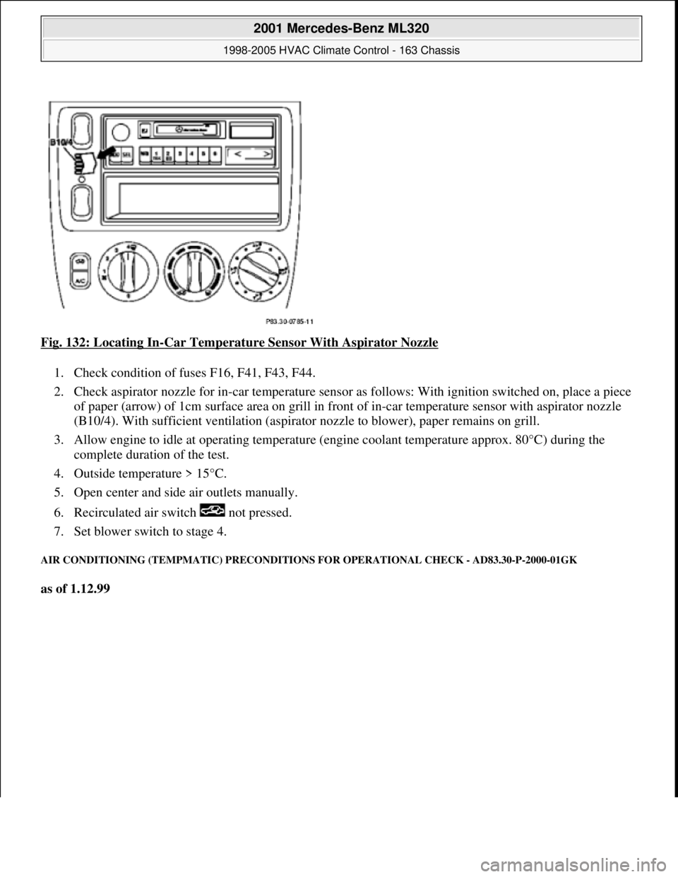
Fig. 132: Locating In-Car Temperature Sensor With Aspirator Nozzle
1. Check condition of fuses F16, F41, F43, F44.
2. Check aspirator nozzle for in-car temperature sensor as follows: With ignition switched on, place a piece
of paper (arrow) of 1cm surface area on grill in front of in-car temperature sensor with aspirator nozzle
(B10/4). With sufficient ventil ation (aspirator nozzle to blow er), paper remains on grill.
3. Allow engine to idle at operating temperature (engine coolant temperature approx. 80°C) during the
complete duration of the test.
4. Outside temperature > 15°C.
5. Open center and side air outlets manually.
6. Recirculated air switch not pressed.
7. Set blower switch to stage 4.
AIR CONDITIONING (TEMPMATIC ) PRECONDITIONS FOR OPERATIONAL CHECK - AD83.30-P-2000-01GK
as of 1.12.99
2001 Mercedes-Benz ML320
1998-2005 HVAC Climate Control - 163 Chassis
me
Saturday, October 02, 2010 3:23:17 PMPage 163 © 2006 Mitchell Repair Information Company, LLC.
Page 3408 of 4133
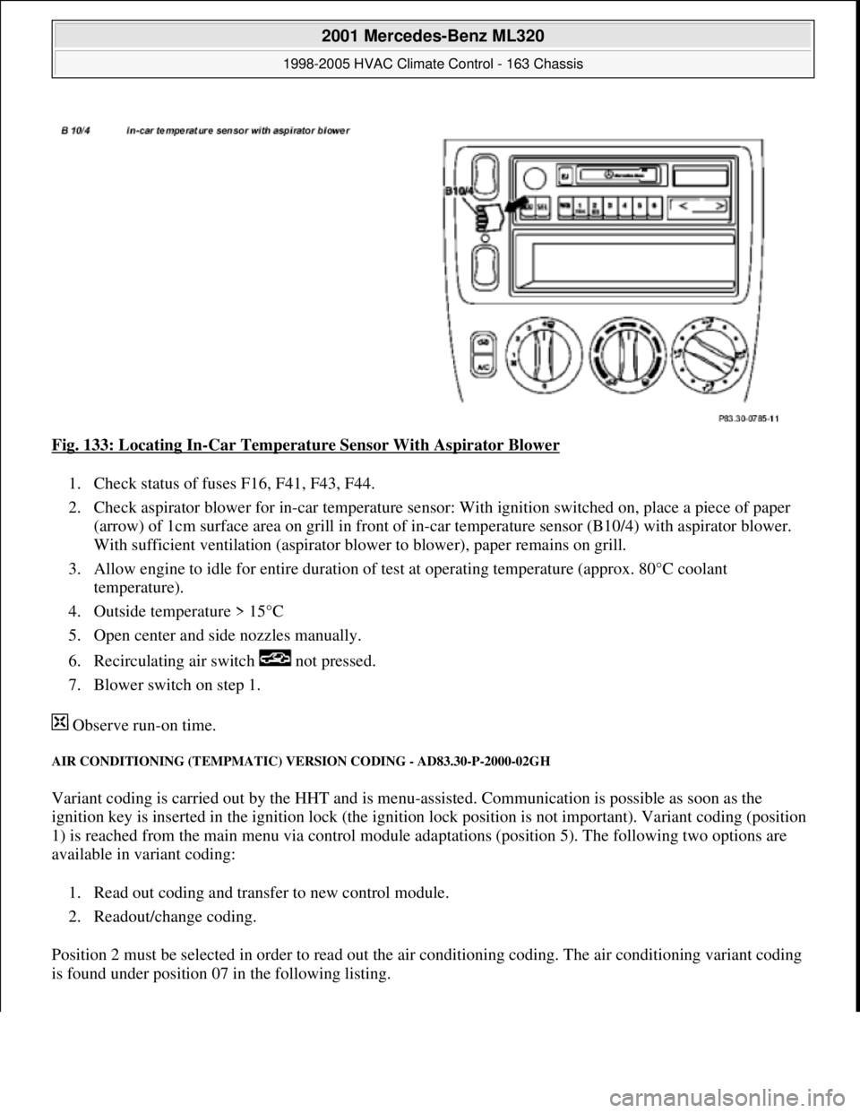
Fig. 133: Locating In-Car Temperature Sensor With Aspirator Blower
1. Check status of fuses F16, F41, F43, F44.
2. Check aspirator blower for in-car temperature sensor: With ignition switched on, place a piece of paper
(arrow) of 1cm surface area on grill in front of in-car temperature sensor (B10/4) with aspirator blower.
With sufficient ventilation (a spirator blower to blower), paper remains on grill.
3. Allow engine to idle for entire duration of test at operating temperature (approx. 80°C coolant
temperature).
4. Outside temperature > 15°C
5. Open center and side nozzles manually.
6. Recirculating air sw itch not pressed.
7. Blower switch on step 1.
Observe run-on time.
AIR CONDITIONING (T EMPMATIC) VERSION CO DING - AD83.30-P-2000-02GH
Variant coding is carried out by the HHT and is menu -assisted. Communication is possible as soon as the
ignition key is inserted in the ignition lock (the igniti on lock position is not important). Variant coding (position
1) is reached from the main menu via control module adaptations (position 5). The following two options are
available in variant coding:
1. Read out coding and transfer to new control module.
2. Readout/change coding.
Position 2 must be selected in order to read out th e air conditioning coding. The air conditioning variant coding
is found under position 07 in the following listing.
2001 Mercedes-Benz ML320
1998-2005 HVAC Climate Control - 163 Chassis
me
Saturday, October 02, 2010 3:23:17 PMPage 164 © 2006 Mitchell Repair Information Company, LLC.
Page 3413 of 4133
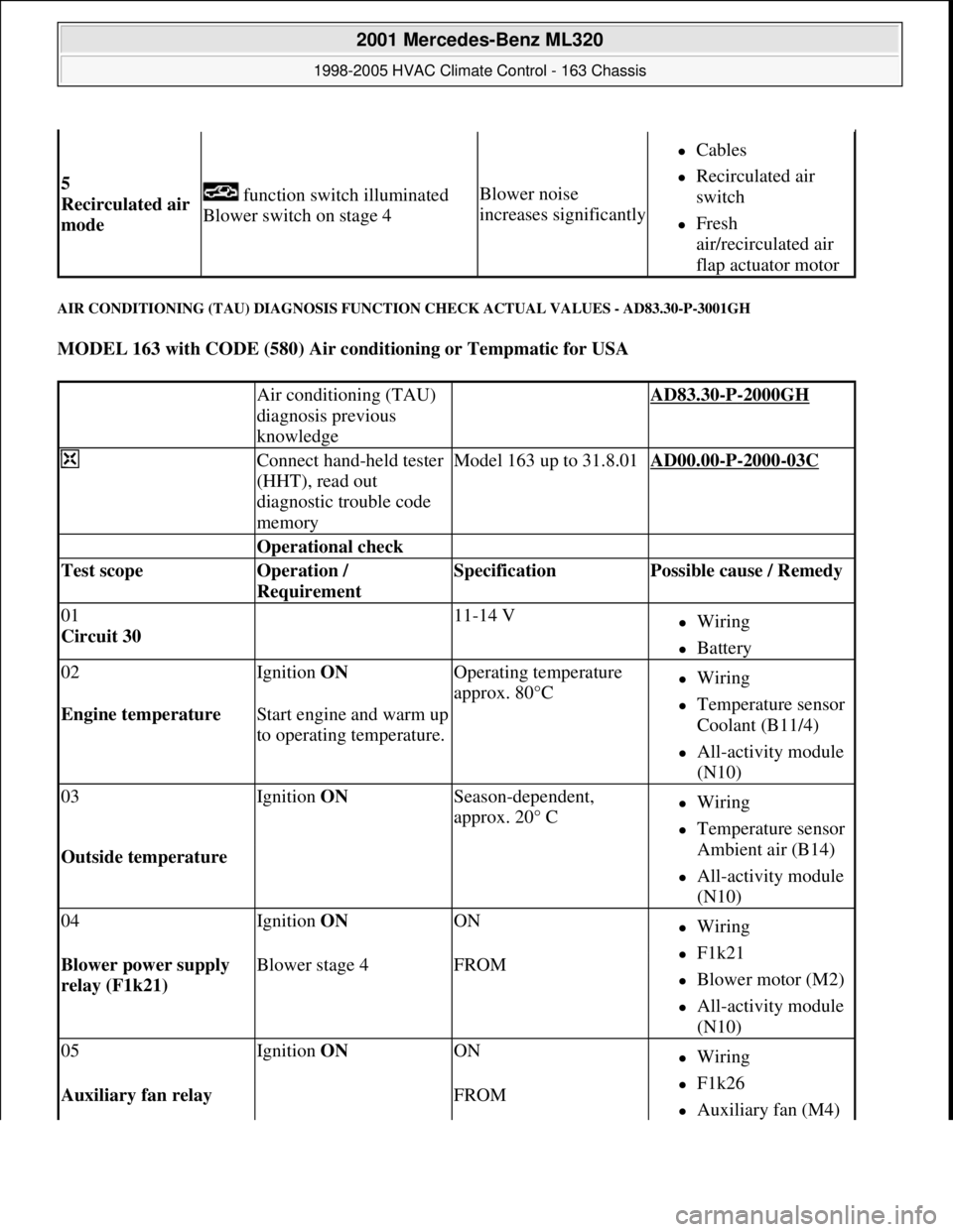
AIR CONDITIONING (TAU) DIAGNOSIS FUNCTION CHECK ACTUAL VALUES - AD83.30-P-3001GH
MODEL 163 with CODE (580) Air conditioning or Tempmatic for USA
5
Recirculated air
mode function switch illuminated
Blower switch on stage 4Blower noise
increases significantly
Cables
Recirculated air
switch
Fresh
air/recirculated air
flap actuator motor
Air conditioning (TAU)
diagnosis previous
knowledge AD83.30-P-2000GH
Connect hand-held tester
(HHT), read out
diagnostic trouble code
memoryModel 163 up to 31.8.01AD00.00-P-2000-03C
Operational check
Test scope Operation /
Requirement Specification Possible cause / Remedy
01
Circuit 30 11-14 VWiring
Battery
02Ignition ON Operating temperature
approx. 80°CWiring
Temperature sensor
Coolant (B11/4)
All-activity module
(N10)
Engine temperature Start engine and warm up
to operating temperature.
03Ignition ON Season-dependent,
approx. 20° CWiring
Temperature sensor
Ambient air (B14)
All-activity module
(N10)
Outside temperature
04Ignition ON ONWiring
F1k21
Blower motor (M2)
All-activity module
(N10)
Blower power supply
relay (F1k21) Blower stage 4FROM
05Ignition ON ONWiring
F1k26
Auxiliary fan (M4) Auxiliary fan relay FROM
2001 Mercedes-Benz ML320
1998-2005 HVAC Climate Control - 163 Chassis
me
Saturday, October 02, 2010 3:23:17 PMPage 169 © 2006 Mitchell Repair Information Company, LLC.