check engine MERCEDES-BENZ ML500 1997 Complete Repair Manual
[x] Cancel search | Manufacturer: MERCEDES-BENZ, Model Year: 1997, Model line: ML500, Model: MERCEDES-BENZ ML500 1997Pages: 4133, PDF Size: 88.89 MB
Page 3835 of 4133

SI18.00-P-0010A
Service Information: oil sludge
26.3.01
ENGINE
111 in MODELS 124, 163, 170, 202, 203, 208, 210
ENGINE
112 in MODELS 129, 163, 170, 202, 203, 208, 210, 220
ENGINE
112, 113 in MODEL 463
ENGINE
113 in MODELS 129, 163, 202, 208, 210, 215, 220
ENGINE
137 in MODEL 215, 220
ENGINE
166 in MODEL 168
Oil sludging in gasoline engines with ASSYST maintenance
system
Recently we have determined that time and time again oil
sludging occurs in gasoline engines with an ASSYST maintenance
system.
Oil sludging can lead to the following complaints:
D
engine oil consumption
D
engine smoke (white/blue)
D
influencing of oil level indicator
D
clogged oil filter, engine oil thickened like jelly
D
Check engine lamp illuminated
D
oil sludge visible during assembly job, e.g. in oil filter, in cylinder
head covers, condensation sludging
(engine 166) etc.
-----------------------------------------------------------------------------------------
The following list of causes may lead individually or as a combination
to engine oil sludging:
D
Crankcase ventilation inoperable, function orifices, bores,
passages in cylinder head cover, cylinder head, crankcase etc.
are mechanically sealed. A nonfunctioning crankcase
ventilation boosts loads on the engine oil through organic
nitrates. The risk of oil sludging increases.
The mechanical condition of the engine is always to be
checked, i.e. all engine oil drain orifices on the cylinder head
and crankcase and all crankcase ventilation ducts must be free
of obstacles. Crankcase breather lines may not be kinked.
Check the ventilation bores in the cylinder head covers.
-----------------------------------------------------------------------------------------
D
The engine oil used does not comply with the specifications in
Sheet 229.1 or 229.3 of the Specifications for Service Products.
The additive process, e.g. dirt-carrying capability, neutralization
capability and oxidation resistance as well as the quality of the
base stock influence sludging time.
Use of engine oils with best possible resistance to formation of
sludge, i.e. use only tested and approved engine oils (from
Sheet 229.1 or 229.3). The best protection is afforded by the
engine oils on Sheet 229.3, which fulfill more stringent
specifications with regard to preventing sludge and deposits
(see Sheet 221.0, page 11). These oils have a distinctly better
anti-sludge characteristic than other engine oils.
D
Sludging after adding a fuel or engine oil special additive.
Do not use fuel or engine oil special additives. More information
hereto is available on Sheet 219.0 of the Specifications for
Service products. Reference to customer not to use special
additives.
D
Engine oil change not performed according to ASSYST
specifications. At driven distances
exceeding > approx. 3000 km, engine oil sludging may occur.
-----------------------------------------------------------------------------------------
Comply with engine oil and filter change as under ASSYST
specifications. Observe remaining distance.
D
Fuel grade lies outside standard (regionally contingent). If
contaminated, deficient fuel is used, then engine oil sludging
may occur even where approved engine oil is used.
Operation with fuel, e.g. as under DIN EN 228. Clarify refueling
behavior of customer. If engine operation regional, is
temporarily possible with deficient oil only, then the startup
distance has to be individually reduced, i.e. the oil change
temporarily performed at an interval of, e.g. 10,000 km.
D
Radiator antifreeze penetration into engine oil, e.g. through an
internal engine leak (cylinder head gasket, casting porosity).
The engine oil sludges within a short period. The crankcase
ventilation clogs up and stops functioning. Condensation
sludging clogs up the oil separator cells
(engine 166).
Rectify coolant leakage. Clean all sludged engine parts, in
particular the crankcase ventilation parts. If the occurrence
repeats, and casting porosity is suspected, e.g. replace
crankcase.
-----------------------------------------------------------------------------------------
Copyright DaimlerChrysler AG 20.05.2006 CD-Ausgabe G/10/04 . This WIS print-out will not be recorde
d by Modification services.
Page 1
Page 3843 of 4133
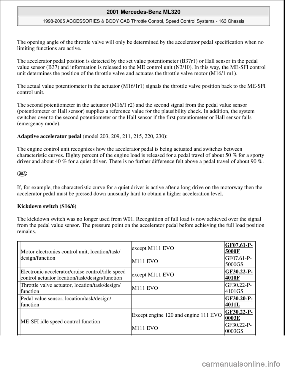
The opening angle of the throttle valve will only be determined by the accelerator pedal specification when no
limiting functions are active.
The accelerator pedal position is detected by the set value potentiometer (B37r1) or Hall sensor in the pedal
value sensor (B37) and information is released to the ME control unit (N3/10). In this way, the ME-SFI control
unit determines the position of the throttle valve and actuates the throttle valve motor (M16/1 m1).
The actual value potentiometer in the actuator (M16/1r1) signals the throttle valve position back to the ME-SFI
control unit.
The second potentiometer in the actuator (M16/1 r2) and the second signal from the pedal value sensor
(potentiometer or Hall sensor) supplies a reference value for the plausibility check. In addition, the system
switches over to the second potentiometer or the Hall sensor if the first potentiometer or Hall sensor fails
(emergency mode).
Adaptive accelerator pedal (model 203, 209, 211, 215, 220, 230):
The engine control unit recognizes how the accelerator pedal is being actuated and switches between
characteristic curves. Eighty percent of the engine load is released for a pedal travel of about 50 % for a sporty
driver and about 40 % for a quiet driver. There is no further difference felt above a pedal travel of about 90 %.
If, for example, the characteristic curve for a quiet driver is active after a long drive on the motorway then the
accelerator pedal must be pressed down unusually hard to obtain a higher acceleration level.
Kickdown switch (S16/6)
The kickdown switch was no longer used from 9/01. Recognition of full load is now achieved over the signal
from the pedal value sensor. The pressure point on the accelerator pedal before achieving the full load position
remains.
Motor electronics control unit, location/task/
design/functionexcept M111 EVOGF07.61-P-
5000F
M111 EVOGF07.61-P-
5000GS
Electronic accelerator/cruise control/idle speed
control actuator location/task/design/functionexcept M111 EVOGF30.22-P-
4010F
Throttle valve actuator, location/task/design/
functionM111 EVOGF30.22-P-
4101GS
Pedal value sensor, location/task/design/
function GF30.20-P-
4011L
ME-SFI idle speed control function
Except engine 120 and engine 111 EVOGF30.22-P-
0003E
M111 EVOGF30.22-P-
0003GS
2001 Mercedes-Benz ML320
1998-2005 ACCESSORIES & BODY CAB Throttle Control, Speed Control Systems - 163 Chassis
me
Saturday, October 02, 2010 3:36:27 PMPage 3 © 2006 Mitchell Repair Information Company, LLC.
Page 3854 of 4133
ENGINE 113.940 /941 /942 /943 /948 /960 /961 /963 /965 /966 /967 /968 /969
ENGINE 119.980 /981 /982 /985
ENGINE 137.970
Task
To allow safe further driving depending on the fault which has arisen in the electronic accelerator pedal system.
Pedal value sensor emergency mode
If the sensor in the pedal value sensor (B37) fails, the system will switch over to the second sensor. The throttle
valve opening is limited to approx. 60%. There is also dynamic limitation of the throttle valve's opening speed
where the throttle valve opening is delayed (the indicator lamp EPC does not light up).
If the plausibility check delivers a negative result or both sensors are defect only the idling speed will be
regulated (the indicator lamp EPC lights up).
Actuator for the throttle valve - emergency running, electrical
If a potentiometer in the actuator for the throttle valve breaks down the system switches-over to the second
intact potentiometer. The air flow mass serves as a second parameter for comparative purposes. Following a
plausibility check, the throttle valve opening is limited to approx. 60% in line with engine speed and load (EPC
indicator lamp does not come on).
If the plausibility check is negative or if both potentiometers are faulty, the throttle valve adopts a mechanical
emergency running position which is fixed by the spring capsule in the actuator (EPC indicator lamp comes on).
Actuator for the throttle valve - emergency running, mechanical emergency running stop
If the actuator motor is defect or there are other faults present the power supply to the actuator will be shut off.
The throttle valve then lies on the mechanical stop (spring box) so the throttle valve opening remains at a
constant 10-12°. At no engine load (idling) engine speed is regulated to about 900 rpm by shutting off or
activating the cylinders at the fuel side.
When driving, engine speed is controlled, in line with the engine load, by switching the cylinders off and on at
the fuel side. The maximum engine speed is about 1800 rpm. which is limited by the mechanical stop (the
indicator lamp EPC lights up).
Safety fuel shutoff
If a mechanical fault exists in the actuator, the safety fuel shutoff is activated.
Here the fuel injection valves are shut off for engine speeds < 1400 rpm and actuated again at speeds < 1200
rpm (the indicator lamp EPC li
ghts up).
2001 Mercedes-Benz ML320
1998-2005 ACCESSORIES & BODY CAB Throttle Control, Speed Control Systems - 163 Chassis
me
Saturday, October 02, 2010 3:36:27 PMPage 14 © 2006 Mitchell Repair Information Company, LLC.
Page 3861 of 4133
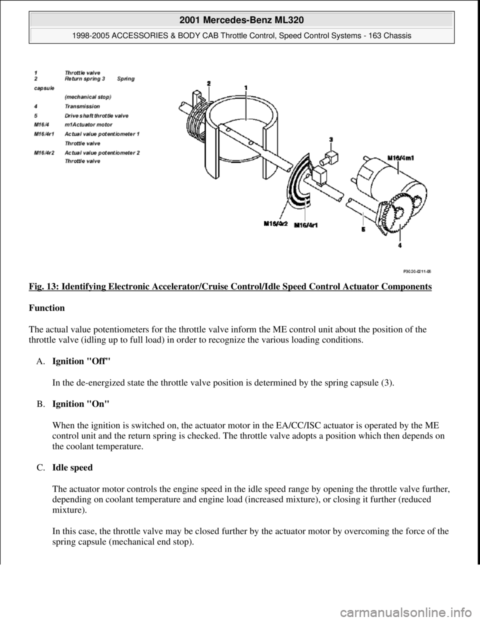
Fig. 13: Identifying Electronic Accelerator/Cruise Control/Idle Speed Control Actuator Components
Function
The actual value potentiometers for the throttle valve inform the ME control unit about the position of the
throttle valve (idling up to full load) in order to recognize the various loading conditions.
A.Ignition "Off"
In the de-energized state the throttle valve position is determined by the spring capsule (3).
B.Ignition "On"
When the ignition is switched on, the actuator motor in the EA/CC/ISC actuator is operated by the ME
control unit and the return spring is checked. The throttle valve adopts a position which then depends on
the coolant temperature.
C.Idle speed
The actuator motor controls the engine speed in the idle speed range by opening the throttle valve further,
depending on coolant temperature and engine load (increased mixture), or closing it further (reduced
mixture).
In this case, the throttle valve may be closed further by the actuator motor by overcoming the force of the
sprin
g capsule (mechanical end stop).
2001 Mercedes-Benz ML320
1998-2005 ACCESSORIES & BODY CAB Throttle Control, Speed Control Systems - 163 Chassis
me
Saturday, October 02, 2010 3:36:27 PMPage 21 © 2006 Mitchell Repair Information Company, LLC.
Page 3872 of 4133
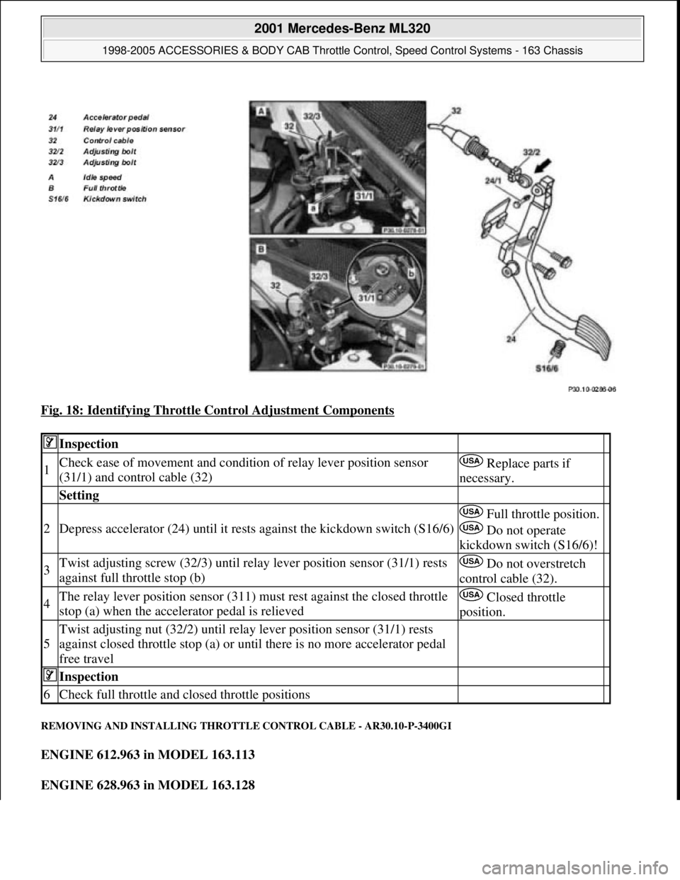
Fig. 18: Identifying Throttle Control Adjustment Components
REMOVING AND INSTALLING THROTTLE CONTROL CABLE - AR30.10-P-3400GI
ENGINE 612.963 in MODEL 163.113
ENGINE 628.963 in MODEL 163.128
Inspection
1Check ease of movement and condition of relay lever position sensor
(31/1) and control cable (32) Replace parts if
necessary.
Setting
2Depress accelerator (24) until it rests against the kickdown switch (S16/6)
Full throttle position.
Do not operate
kickdown switch (S16/6)!
3Twist adjusting screw (32/3) until relay lever position sensor (31/1) rests
against full throttle stop (b) Do not overstretch
control cable (32).
4The relay lever position sensor (311) must rest against the closed throttle
stop (a) when the accelerator pedal is relieved Closed throttle
position.
5
Twist adjusting nut (32/2) until relay lever position sensor (31/1) rests
against closed throttle stop (a) or until there is no more accelerator pedal
free travel
Inspection
6Check full throttle and closed throttle positions
2001 Mercedes-Benz ML320
1998-2005 ACCESSORIES & BODY CAB Throttle Control, Speed Control Systems - 163 Chassis
me
Saturday, October 02, 2010 3:36:28 PMPage 32 © 2006 Mitchell Repair Information Company, LLC.
Page 3874 of 4133
REMOVING AND INSTALLING ACCELERATOR PEDAL - AR30.12-P-1321GH
ENGINE 111.977 in MODEL 163.136
ENGINE 112.942 in MODEL 163.154
ENGINE 112.970 in MODEL 163.157
ENGINE 113.981 in MODEL 163.174
6Push control cable (32) from vehicle interior
towards the outside Do not push rubber grommet out
of splash wall.
7Remove entire control cable (32) from engine
compartment
8Install in the reverse order
9Check throttle control, adjust
Engine 112.942/970,
113.942/965/981 ?
Automatic transmissionAR30.10-P-
1010GJ
Engine 612.963: ?
Manual/automatic transmissionAR30.10-P-
1010GH
Engine 628.963: ?
Automatic transmissionAR30.10-P-
1010GH
2001 Mercedes-Benz ML320
1998-2005 ACCESSORIES & BODY CAB Throttle Control, Speed Control Systems - 163 Chassis
me
Saturday, October 02, 2010 3:36:28 PMPage 34 © 2006 Mitchell Repair Information Company, LLC.
Page 3876 of 4133
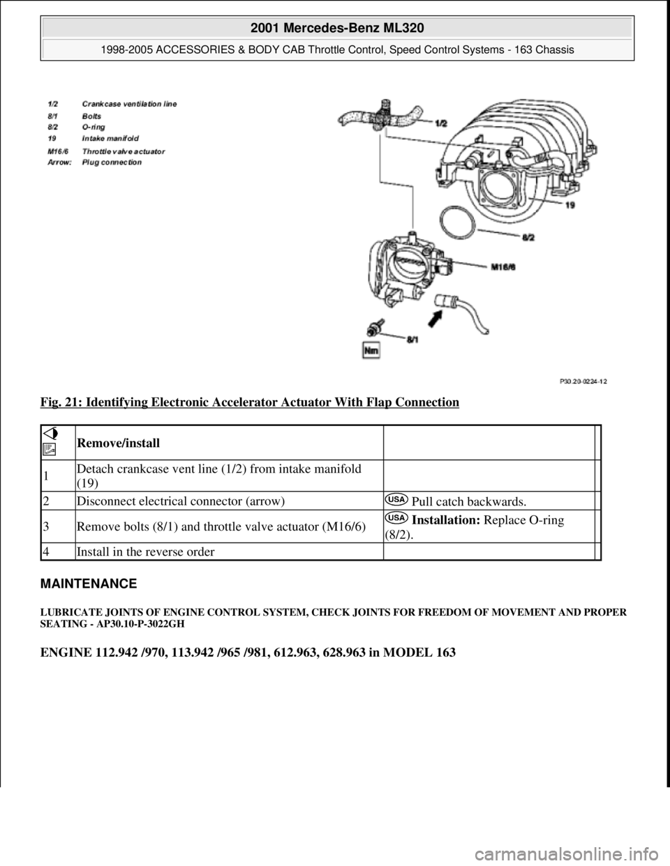
Fig. 21: Identifying Electronic Accelerator Actuator With Flap Connection
MAINTENANCE
LUBRICATE JOINTS OF ENGINE CONTROL SYSTEM, CHECK JOINTS FOR FREEDOM OF MOVEMENT AND PROPER
SEATING - AP30.10-P-3022GH
ENGINE 112.942 /970, 113.942 /965 /981, 612.963, 628.963 in MODEL 163
Remove/install
1Detach crankcase vent line (1/2) from intake manifold
(19)
2Disconnect electrical connector (arrow) Pull catch backwards.
3Remove bolts (8/1) and throttle valve actuator (M16/6) Installation: Replace O-ring
(8/2).
4Install in the reverse order
2001 Mercedes-Benz ML320
1998-2005 ACCESSORIES & BODY CAB Throttle Control, Speed Control Systems - 163 Chassis
me
Saturday, October 02, 2010 3:36:28 PMPage 36 © 2006 Mitchell Repair Information Company, LLC.
Page 3877 of 4133
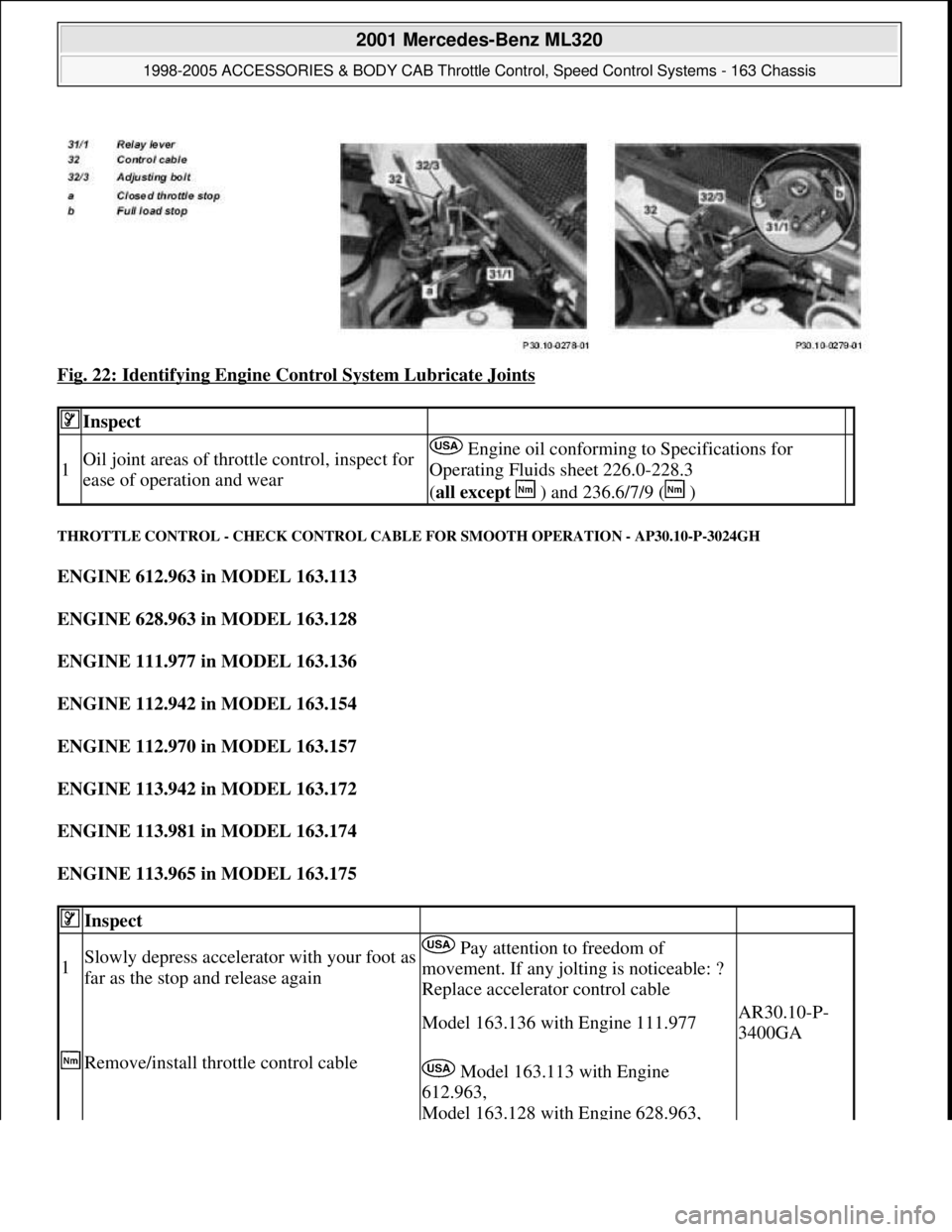
Fig. 22: Identifying Engine Control System Lubricate Joints
THROTTLE CONTROL - CHECK CONTROL CABLE FOR SMOOTH OPERATION - AP30.10-P-3024GH
ENGINE 612.963 in MODEL 163.113
ENGINE 628.963 in MODEL 163.128
ENGINE 111.977 in MODEL 163.136
ENGINE 112.942 in MODEL 163.154
ENGINE 112.970 in MODEL 163.157
ENGINE 113.942 in MODEL 163.172
ENGINE 113.981 in MODEL 163.174
ENGINE 113.965 in MODEL 163.175
Inspect
1Oil joint areas of throttle control, inspect for
ease of operation and wear Engine oil conforming to Specifications for
Operating Fluids sheet 226.0-228.3
(all except ) and 236.6/7/9 ( )
Inspect
1Slowly depress accelerator with your foot as
far as the stop and release again Pay attention to freedom of
movement. If any jolting is noticeable: ?
Replace accelerator control cable
Remove/install throttle control cable
Model 163.136 with Engine 111.977AR30.10-P-
3400GA
Model 163.113 with Engine
612.963,
Model 163.128 with Engine 628.963,
2001 Mercedes-Benz ML320
1998-2005 ACCESSORIES & BODY CAB Throttle Control, Speed Control Systems - 163 Chassis
me
Saturday, October 02, 2010 3:36:28 PMPage 37 © 2006 Mitchell Repair Information Company, LLC.
Page 3883 of 4133
2001-04 STARTING & CHARGING SYSTEMS Starters - 163 Chassis
MODEL IDENTIFICATION
MODEL IDENTIFICATION
DESCRIPTION
Starter is a brush-type, series-wound el ectric motor with an overrunning clutch. Field frame contains field coils
and is enclosed by commutator/drive bushing end frame, which carries pole shoes. A splined armature shaft
carries drive assembly.
TROUBLE SHOOTING
BASIC TROUBLESHOOTING
If starter is noisy, the cause could be bent or damaged gear tooth chamfers on ring gear. This cannot be seen
with starter installed in ve hicle. Activate starter without switching ignition on. Me tallic noise should not be
heard. If noise is he ard, replace ring gear.
PRELIMINARY INSPECTION
Verify customer complaint by operating system. Visually inspect for obvious signs of mechanical and electrical
damage. Check generator belt tension and condition. Ensure that battery voltage is within specifications. Inspect
for blown fuses and damaged relays. For fuse and/or relay identification, see WIRING DIAGRAMS
.
WARNING:
Vehicles are equipped with air bag supplemental restraint system. Before
attempting any repairs involving steer ing column, instrument panel or
related components, see SERVICE PRECAUTIONS (or AIR BAG SAFETY
PRECAUTIONS) and DISABLING & ACTIVATING AIR BAG SYSTEM in
appropriate AIR BAG REST RAINT SYSTEMS article.
NOTE: When the battery is di sconnected, vehicle computer and memory system may
lose data. Driveability problems may exist until computer systems have
completed a relearn cycle. Radio will not operate until coded. Obtain code card
from customer.
NOTE: The following table identifies mo dels applicable to this article.
ModelChassisEngine Number
ML430 (2001)163.172113.942
ML320 (2001-03)163.154112.942
ML55 AMG (2001-03)163.174113.981
ML500 (2002-04)163.175113.965
ML350 (2003-04)163.157112.970
2001 Mercedes-Benz ML320
2001-04 STARTING & CHARGING SYSTEMS Starters - 163 Chassis
2001 Mercedes-Benz ML320
2001-04 STARTING & CHARGING SYSTEMS Starters - 163 Chassis
me
Saturday, October 02, 2010 3:19:47 PMPage 1 © 2006 Mitchell Repair Information Company, LLC.
me
Saturday, October 02, 2010 3:19:50 PMPage 1 © 2006 Mitchell Repair Information Company, LLC.
Page 3884 of 4133
Verify ground connection integrity between engine, body, battery and generator. Check for damaged wiring
harnesses and/or switches. Check fo r a broken or partially broken wire inside insulation, which could cause
system malfunction but prove good in a continuity/vol tage check with system disconnected. Ensure any
aftermarket electronic e quipment is properly installed. If fault is found, repair as necessary. If no fault is found,
check for conditions that might cause an intermittent situation.
SERVICE PRECAUTIONS
BATTERY DISCONNECT/CONNECT
Disconnect/Connect Procedures
1. Turn ignition off. Open engine hood. After opening ve hicle wait at least 4 minutes before disconnecting
battery or alarm wi ll be triggered.
2. Disconnect negative battery cable (1) and insulate cable lug to prevent unwanted contact with ground
point (W16/4). See Fig. 1
.
3. To connect, reverse disconnect procedur e. Tighten nut (5) to specification. See TORQUE
SPECIFICATIONS .
4. Perform basic programming, read Diagnostic Tr ouble Code (DTC) memory and erase DTCs from
memory. See BASIC PROGRAMMING
and RETRIEVING & ERASING DIAGNOSTIC
TROUBLE CODES .
NOTE: Numbers and letters in text refe
r to numbers and letters in figures.
2001 Mercedes-Benz ML320
2001-04 STARTING & CHARGING SYSTEMS Starters - 163 Chassis
me
Saturday, October 02, 2010 3:19:47 PMPage 2 © 2006 Mitchell Repair Information Company, LLC.