check engine MERCEDES-BENZ ML500 1997 Complete Repair Manual
[x] Cancel search | Manufacturer: MERCEDES-BENZ, Model Year: 1997, Model line: ML500, Model: MERCEDES-BENZ ML500 1997Pages: 4133, PDF Size: 88.89 MB
Page 3429 of 4133
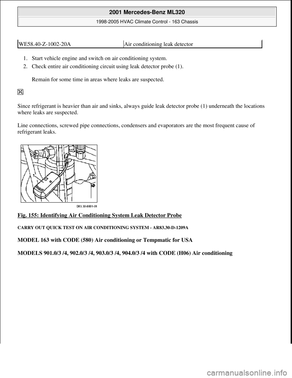
1. Start vehicle engine and switch on air conditioning system.
2. Check entire air conditioning circuit using leak detector probe (1).
Remain for some time in areas where leaks are suspected.
Since refrigerant is heavier than air and sinks, always guide leak detector probe (1) underneath the locations
where leaks are suspected.
Line connections, screwed pipe connections, condensers and evaporators are the most frequent cause of
refrigerant leaks.
Fig. 155: Identifying Air Conditioning System Leak Detector Probe
CARRY OUT QUICK TEST ON AIR CONDITIONING SYSTEM - AR83.30-D-1209A
MODEL 163 with CODE (580) Air conditioning or Tempmatic for USA
MODELS 901.0/3 /4, 902.0/3 /4, 903.0/3 /4, 904.0/3 /4 with CODE (H06) Air conditioning
WE58.40-Z-1002-20AAir conditioning leak detector
2001 Mercedes-Benz ML320
1998-2005 HVAC Climate Control - 163 Chassis
me
Saturday, October 02, 2010 3:23:18 PMPage 185 © 2006 Mitchell Repair Information Company, LLC.
Page 3430 of 4133
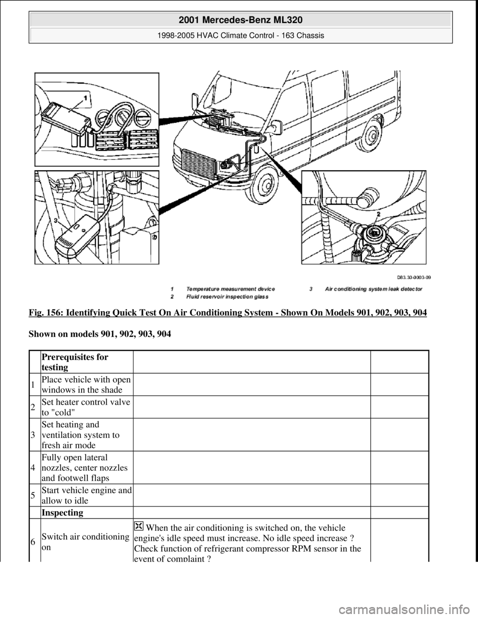
Fig. 156: Identifying Quick Test On Air Conditioning System - Shown On Models 901, 902, 903, 904
Shown on models 901, 902, 903, 904
Prerequisites for
testing
1Place vehicle with open
windows in the shade
2Set heater control valve
to "cold"
3
Set heating and
ventilation system to
fresh air mode
4
Fully open lateral
nozzles, center nozzles
and footwell flaps
5Start vehicle engine and
allow to idle
Inspecting
6Switch air conditioning
on
When the air conditioning is switched on, the vehicle
engine's idle speed must increase. No idle speed increase ?
Check function of refrigerant compressor RPM sensor in the
event of complaint ?
2001 Mercedes-Benz ML320
1998-2005 HVAC Climate Control - 163 Chassis
me
Saturday, October 02, 2010 3:23:18 PMPage 186 © 2006 Mitchell Repair Information Company, LLC.
Page 3431 of 4133
Commercially available tools
Workshop equipment
DRAINING, EVACUATING AND REFILLING AIR CONDITIONING, CHECKING FUNCTION AND CHECKING FOR
LEAKS - AR83.30-P-1760GH
MODELS 163.113 /128 /136 /154 /157 /172 /174 /175 with CODE (580) Air conditioning or Tempmatic for
USA
Replace refrigerant compressor RPM sensor
Models 901-904
Not in model 163AR83.55-D-
5320A
7
Set blower rotary
switch to maximum
blower setting
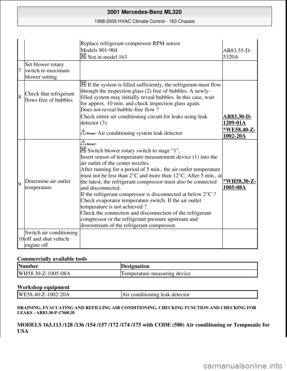
8Check that refrigerant
flows free of bubbles
If the system is filled sufficiently, the refrigerant must flow
through the inspection glass (2) free of bubbles. A newly-
filled system may initially reveal bubbles. In this case, wait
for approx. 10 min. and check inspection glass again.
Does not reveal bubble-free flow ?
Check entire air conditioning circuit for leaks using leak
detector (3).AR83.30-D-
1209-01A
Air conditioning system leak detector*WE58.40-Z-
1002-20A
9Determine air outlet
temperature
Switch blower rotary switch to stage "1".
Insert sensor of temperature measurement device (1) into the
air outlet of the center nozzles.
After running for a period of 5 min., the air outlet temperature
must not be less than 2°C and more than 12°C. After 5 min., at
the latest, the refrigerant compressor must also be connected
and disconnected.
If the refrigerant compressor is disconnected at below 2°C ?
Check evaporator temperature switch. If the air outlet
temperature is not achieved ?
Check the connection and disconnection of the refrigerant
compressor or the refrigerant pressure upstream and
downstream of the refrigerant compressor.
*WH58.30-Z-
1005-08A
10
Switch air conditioning
off and shut vehicle
engine off
NumberDesignation
WH58.30-Z-1005-08ATemperature measuring device
WE58.40-Z-1002-20AAir conditioning leak detector
2001 Mercedes-Benz ML320
1998-2005 HVAC Climate Control - 163 Chassis
me
Saturday, October 02, 2010 3:23:18 PMPage 187 © 2006 Mitchell Repair Information Company, LLC.
Page 3433 of 4133
Air conditioning system
Workshop equipment
REMOVE/INSTALL DEFROSTER VENT FLAP ACTUATOR MOTOR FOR WINDSHIELD - AR83.30-P-2006GH
MODEL 163.113 /154 /174 #A as of 289565, 163.113 #X as of 754620, 163.128/157/175
4evacuate
Filling
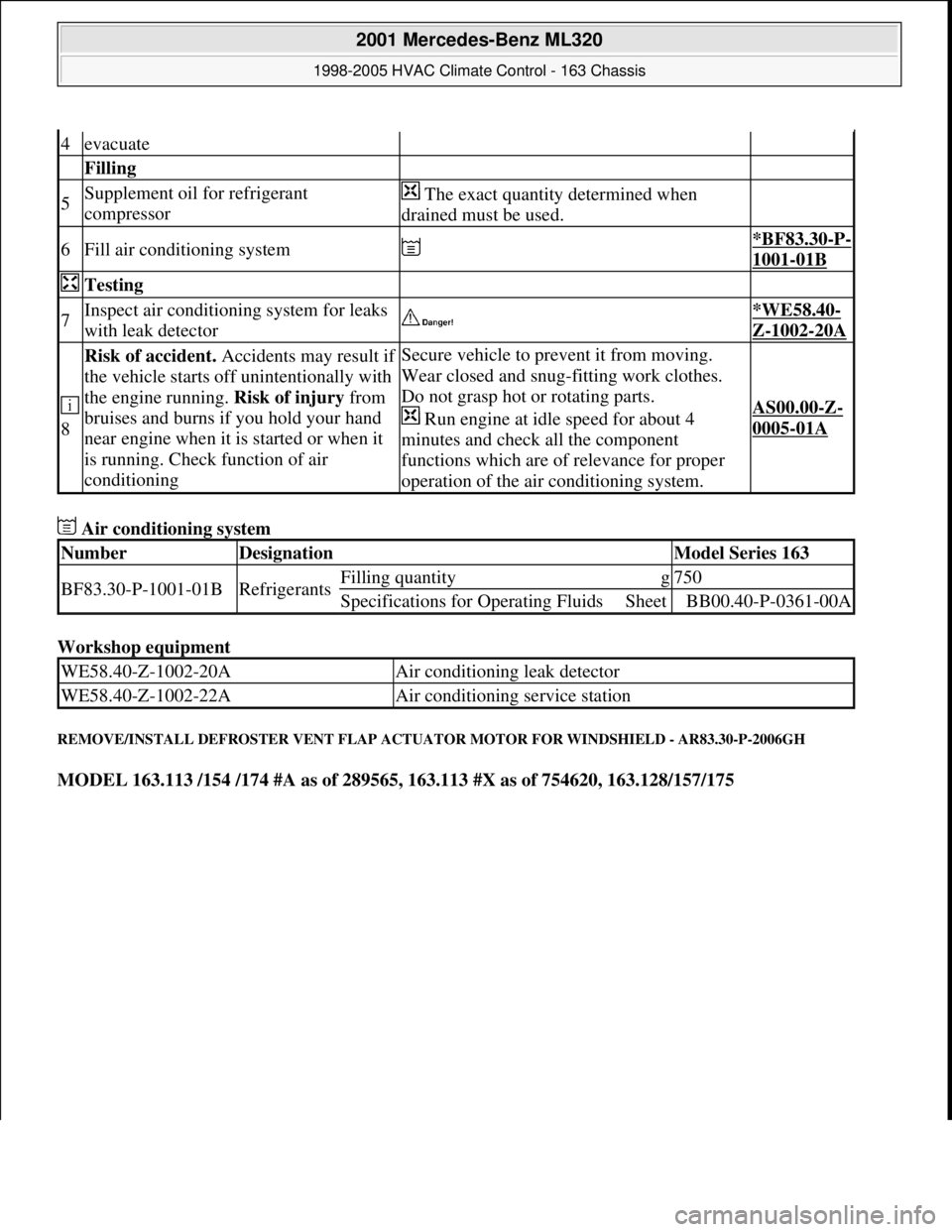
5Supplement oil for refrigerant
compressor The exact quantity determined when
drained must be used.
6Fill air conditioning system *BF83.30-P-
1001-01B
Testing
7Inspect air conditioning system for leaks
with leak detector *WE58.40-
Z-1002-20A
8
Risk of accident. Accidents may result if
the vehicle starts off unintentionally with
the engine running. Risk of injury from
bruises and burns if you hold your hand
near engine when it is started or when it
is running. Check function of air
conditioningSecure vehicle to prevent it from moving.
Wear closed and snug-fitting work clothes.
Do not grasp hot or rotating parts.
Run engine at idle speed for about 4
minutes and check all the component
functions which are of relevance for proper
operation of the air conditioning system.
AS00.00-Z-
0005-01A
NumberDesignationModel Series 163
BF83.30-P-1001-01BRefrigerantsFilling quantityg750
Specifications for Operating FluidsSheetBB00.40-P-0361-00A
WE58.40-Z-1002-20AAir conditioning leak detector
WE58.40-Z-1002-22AAir conditioning service station
2001 Mercedes-Benz ML320
1998-2005 HVAC Climate Control - 163 Chassis
me
Saturday, October 02, 2010 3:23:18 PMPage 189 © 2006 Mitchell Repair Information Company, LLC.
Page 3441 of 4133
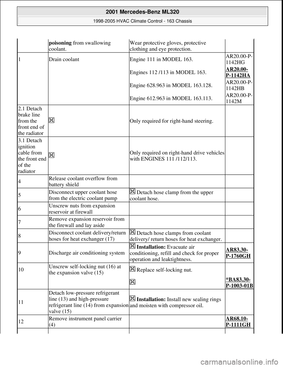
poisoning from swallowing
coolant.Wear protective gloves, protective
clothing and eye protection.
1Drain coolantEngine 111 in MODEL 163.AR20.00-P-
1142HG
Engines 112 /113 in MODEL 163.AR20.00-
P-1142HA
Engine 628.963 in MODEL 163.128.AR20.00-P-
1142HB
Engine 612.963 in MODEL 163.113.AR20.00-P-
1142M
2.1 Detach
brake line
from the
front end of
the radiator
Only required for right-hand steering.
3.1 Detach
ignition
cable from
the front end
of the
radiator
Only required on right-hand drive vehicles
with ENGINES 111 /112/113.
4Release coolant overflow from
battery shield
5Disconnect upper coolant hose
from the electric coolant pump Detach hose clamp from the upper
coolant hose.
6Unscrew nuts from expansion
reservoir at firewall
7Remove expansion reservoir from
the firewall and lay aside
8Disconnect coolant delivery/return
hoses for heat exchanger (17) Detach hose clamps from coolant
delivery/ return hoses for heat exchanger.
9Discharge air conditioning system
Installation: Evacuate air
conditioning, refill and check for proper
operation and leaktightness.AR83.30-
P-1760GH
10Unscrew self-locking nut (16) at
the expansion valve (15) Replace self-locking nut.
*BA83.30-
P-1003-01B
11
Detach low-pressure refrigerant
line (13) and high-pressure
refrigerant line (14) from expansion
valve (15)
Installation: Install new sealing rings
and moisten with compressor oil.
12Remove instrument panel carrier
(4) AR68.10-
P-1111GH
2001 Mercedes-Benz ML320
1998-2005 HVAC Climate Control - 163 Chassis
me
Saturday, October 02, 2010 3:23:18 PMPage 197 © 2006 Mitchell Repair Information Company, LLC.
Page 3446 of 4133
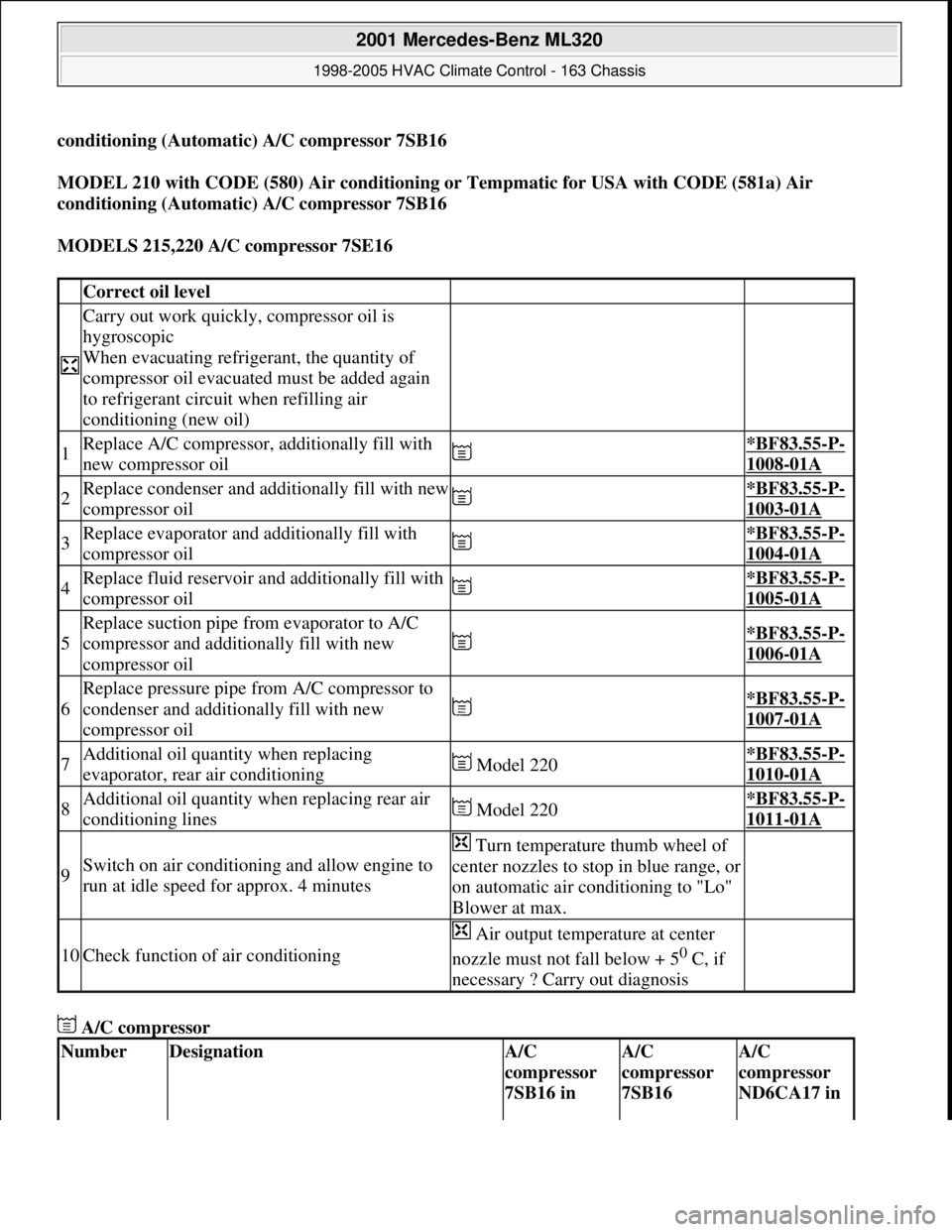
conditioning (Automatic) A/C compressor 7SB16
MODEL 210 with CODE (580) Air conditioning or Tempmatic for USA with CODE (581a) Air
conditioning (Automatic) A/C compressor 7SB16
MODELS 215,220 A/C compressor 7SE16
A/C compressor
Correct oil level
Carry out work quickly, compressor oil is
hygroscopic
When evacuating refrigerant, the quantity of
compressor oil evacuated must be added again
to refrigerant circuit when refilling air
conditioning (new oil)
1Replace A/C compressor, additionally fill with
new compressor oil *BF83.55-P-
1008-01A
2Replace condenser and additionally fill with new
compressor oil *BF83.55-P-
1003-01A
3Replace evaporator and additionally fill with
compressor oil *BF83.55-P-
1004-01A
4Replace fluid reservoir and additionally fill with
compressor oil *BF83.55-P-
1005-01A
5
Replace suction pipe from evaporator to A/C
compressor and additionally fill with new
compressor oil
*BF83.55-P-
1006-01A
6
Replace pressure pipe from A/C compressor to
condenser and additionally fill with new
compressor oil
*BF83.55-P-
1007-01A
7Additional oil quantity when replacing
evaporator, rear air conditioning Model 220*BF83.55-P-
1010-01A
8Additional oil quantity when replacing rear air
conditioning lines Model 220*BF83.55-P-
1011-01A
9Switch on air conditioning and allow engine to
run at idle speed for approx. 4 minutes
Turn temperature thumb wheel of
center nozzles to stop in blue range, or
on automatic air conditioning to "Lo"
Blower at max.
10Check function of air conditioning
Air output temperature at center
nozzle must not fall below + 5
0 C, if
necessary ? Carry out diagnosis
NumberDesignationA/C
compressor
7SB16 in A/C
compressor
7SB16 A/C
compressor
ND6CA17 in
2001 Mercedes-Benz ML320
1998-2005 HVAC Climate Control - 163 Chassis
me
Saturday, October 02, 2010 3:23:18 PMPage 202 © 2006 Mitchell Repair Information Company, LLC.
Page 3457 of 4133
Air conditioning system
Refrigerant compressor
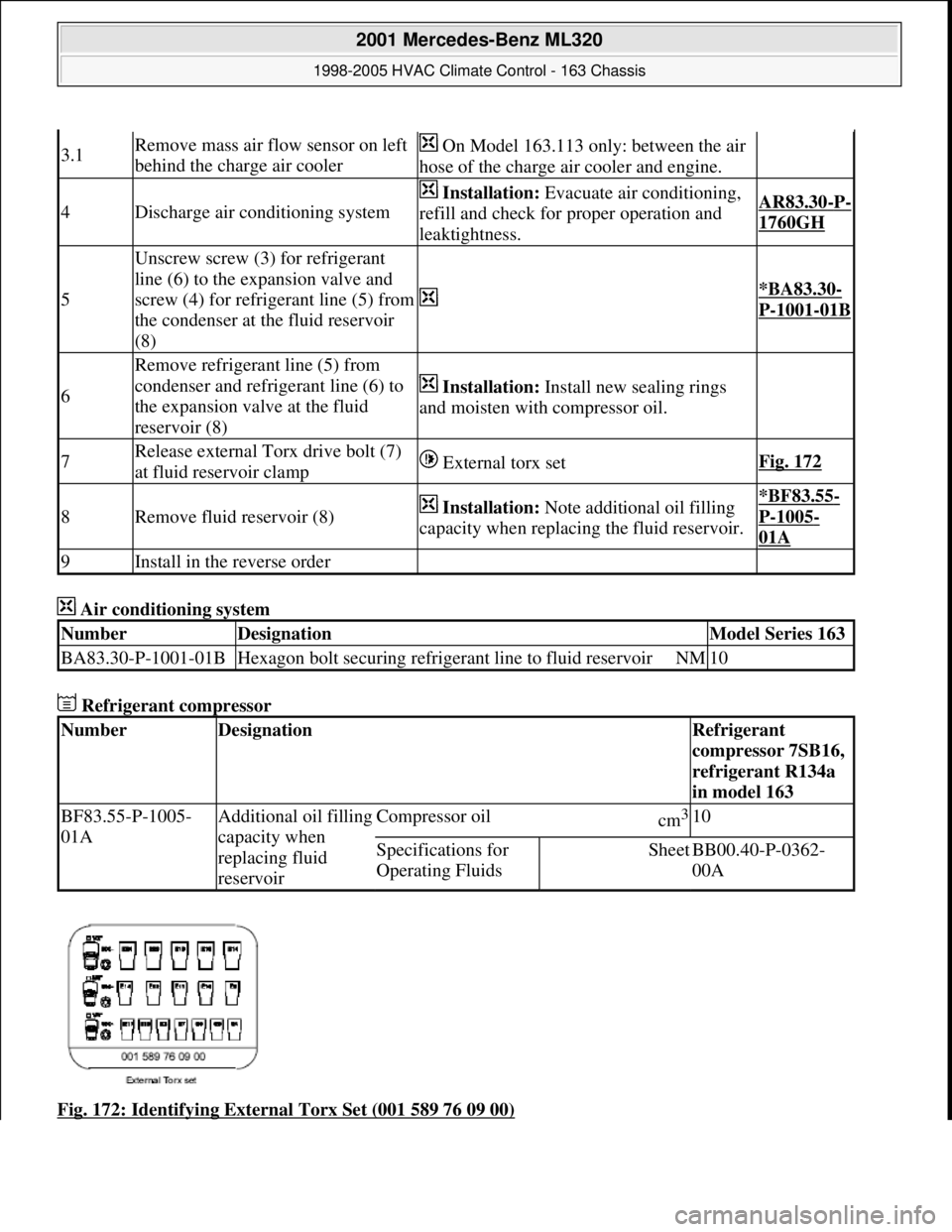
Fig. 172: Identifying External Torx Set (001 589 76 09 00)
3.1Remove mass air flow sensor on left
behind the charge air cooler On Model 163.113 only: between the air
hose of the charge air cooler and engine.
4Discharge air conditioning system
Installation: Evacuate air conditioning,
refill and check for proper operation and
leaktightness.AR83.30-P-
1760GH
5
Unscrew screw (3) for refrigerant
line (6) to the expansion valve and
screw (4) for refrigerant line (5) from
the condenser at the fluid reservoir
(8)
*BA83.30-
P-1001-01B
6
Remove refrigerant line (5) from
condenser and refrigerant line (6) to
the expansion valve at the fluid
reservoir (8)
Installation: Install new sealing rings
and moisten with compressor oil.
7Release external Torx drive bolt (7)
at fluid reservoir clamp External torx setFig. 172
8Remove fluid reservoir (8) Installation: Note additional oil filling
capacity when replacing the fluid reservoir.*BF83.55-
P-1005-
01A
9Install in the reverse order
NumberDesignationModel Series 163
BA83.30-P-1001-01BHexagon bolt securing refrigerant line to fluid reservoirNM10
NumberDesignationRefrigerant
compressor 7SB16,
refrigerant R134a
in model 163
BF83.55-P-1005-
01AAdditional oil filling
capacity when
replacing fluid
reservoirCompressor oilcm3 10
Specifications for
Operating FluidsSheetBB00.40-P-0362-
00A
2001 Mercedes-Benz ML320
1998-2005 HVAC Climate Control - 163 Chassis
me
Saturday, October 02, 2010 3:23:18 PMPage 213 © 2006 Mitchell Repair Information Company, LLC.
Page 3459 of 4133
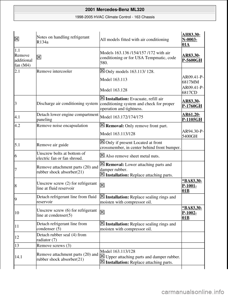
Notes on handling refrigerant
R134aAll models fitted with air conditioning
AH83.30-
N-0003-
01A
1.1
Remove
additional
fan (M4)
Models 163.136 /154/157 /172 with air
conditioning or for USA Tempmatic, code
580.AR83.30-
P-5600GH
2.1Remove intercooler Only models 163.113/ 128.
Model 163.113AR09.41-P-
6817MM
Model 163.128AR09.41-P-
6817CD
3Discharge air conditioning system
Installation: Evacuate, refill air
conditioning system and check for proper
operation and tightness.AR83.30-
P-1760GH
4.1Detach lower engine compartment
panelingModel 163.172/174/175AR61.20-
P-1105GH
4.2Remove noise encapsulation Removal: Only remove front part.
Model 163.113/128AR94.30-P-
5400GH
5.1Remove air guide Only if present Located at front
crossmember, in center behind front bumper.
6Unscrew bolts at bottom of
electric fan or fan shroud. Also remove sheet metal nuts.
7Remove attachment parts (20) and
rubber shock absorber(21) Removal: Lower attaching parts and
damper rubber.
Installation: Replace attaching parts.
8Unscrew screw (2) for refrigerant
line at fluid reservoir
*BA83.30-
P-1001-
01B
9Detach refrigerant line from fluid
reservoir Installation: Replace sealing rings and
moisten with compressor oil.
10Unscrew screw (6) for refrigerant
line at condenser(5)
*BA83.30-
P-1002-
01B
11Detach refrigerant line from
condenser (5) Installation: Replace sealing rings and
moisten with compressor oil.
12Detach rubber seal (4) from
radiator (7)
13Remove screws (3)
14.1Remove attachment parts (20) and
rubber shock absorber(21)Model 163.113/128
Upper attaching parts and damper rubber.
Installation: Replace attaching parts.
2001 Mercedes-Benz ML320
1998-2005 HVAC Climate Control - 163 Chassis
me
Saturday, October 02, 2010 3:23:18 PMPage 215 © 2006 Mitchell Repair Information Company, LLC.
Page 3464 of 4133
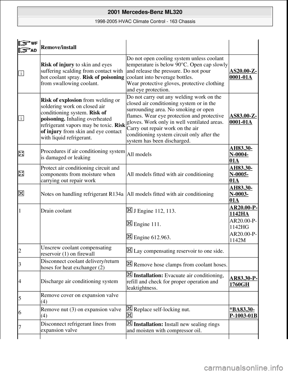
Remove/install
Risk of injury to skin and eyes
suffering scalding from contact with
hot coolant spray. Risk of poisoning
from swallowing coolant.
Do not open cooling system unless coolant
temperature is below 90°C. Open cap slowly
and release the pressure. Do not pour
coolant into beverage bottles.
Wear protective gloves, protective clothing
and eye protection.
AS20.00-Z-
0001-01A
Risk of explosion from welding or
soldering work on closed air
conditioning system. Risk of
poisoning. Inhaling overheated
refrigerant vapors may be toxic. Risk
of injury from skin and eye contact
with liquid refrigerant.Do not carry out any welding work on the
closed air conditioning system or in the
surrounding area. No smoking or open
flames. Wear eye protection and protective
gloves. Work only in well ventilated areas.
Carry out repair work on the air
conditioning system circuit only after the
system has been discharged.
AS83.00-Z-
0001-01A
Procedures if air conditioning system
is damaged or leakingAll models
AH83.30-
N-0004-
01A
Protect air conditioning circuit and
components from moisture when
carrying out repair work
All models fitted with air conditioning
AH83.30-
N-0005-
01A
Notes on handling refrigerant R134aAll models fitted with air conditioning
AH83.30-
N-0003-
01A
1Drain coolant J Engine 112, 113.AR20.00-P-
1142HA
Engine 111.AR20.00-P-
1142HG
Engine 612.963.AR20.00-P-
1142M
2Unscrew coolant compensating
reservoir (1) on firewall Lay compensating reservoir to one side.
3Disconnect coolant delivery/return
hoses for heat exchanger (2) Remove hose clamps from coolant hoses.
4Discharge air conditioning system
Installation: Evacuate air conditioning,
refill and check for proper operation and
leaktightness.AR83.30-P-
1760GH
5Remove cover on expansion valve
(4)
6Remove nut (3) on expansion valve
(4) Replace self-locking nut.
*BA83.30-
P-1003-01B
7Disconnect refrigerant lines from
expansion valve Installation: Install new sealing rings
and moisten with compressor oil.
2001 Mercedes-Benz ML320
1998-2005 HVAC Climate Control - 163 Chassis
me
Saturday, October 02, 2010 3:23:19 PMPage 220 © 2006 Mitchell Repair Information Company, LLC.
Page 3482 of 4133

GF54.30-P-3003A
Indicator/warning messages triggered via CAN data buses, function
24.10.96
MODEL
129, 140 as of 1.6.96,
163, 168, 170,
202 as of 1.8.96,
208 up to 31.7.99,
210 as of 1.6.96 up to 30.6.99
Indicator and warning displays triggered via CAN
Low brake fluid level/parking brake indicator lamp (A1e7)
The parking brake signal comes from the traction system
control module.
The brake fluid signal comes directly from the switch (S11)
(except model 163).
Brake pad wear indicator lamp (A1e6)
The parking brake signal comes from the traction system
control module (N47)
Low engine oil level indicator lamp (A1e12)
The oil level signal comes from the injection system control
module (N3).
For vehicles with ASSYST, also refer to document: ASSYST
engine oil monitoring.
Preglow indicator lamp (A1e16)
The signal comes directly from the injection system control
module (N3).
Coolant level and temperature warning lamp (A1e11) model 168
only as of 9.99
The coolant temperature signal comes from the injection
system control module (N3)
-----------------------------------------------------------------------------------------
ABS MIL (A1e17)
The parking brake signal comes from the traction system
control module (N47).
"CHECK ENGINE" MIL (A1e26),
I
only
The signal comes from the injection system control module (N3)
ETS (A1e35) or ASR (A1e22) or ESP (A1e42) MIL
Lamp illuminated if there is a fault in the respective system.
The signal comes from the traction system control module
(N47).
ETS (A1e36) or ASR (A1e21) or ESP (A1e41) warning lamp
The lamp indicates that the respective system is active.
The signal comes from the traction system control module
(N47).
-----------------------------------------------------------------------------------------
Severe leak warning (
I
as of 97 only)
The fuel reserve indicator lamp (A1e4) flashes. The signal
comes from the injection system control module (N3).
The warning takes place at the earliest 30 minutes after cold
start with the engine idling and the vehicle stationary.
Also refer to document: Purge system with leak test, function
Fog lamps indicator lamp (A1e57), model 163 only except
I
)
The signal comes from the All-activity module (AAM, N10)
"LOW RANGE" indicator lamp (A1e53), model 163 only
The signal comes from the transfer case control module (N78)
Active service system (ASSYST)
Engines 112, 113, 611 (engines with oil
sensor)
GF00.20-P-2009A
Engine oil monitoring, function
Model 210 as of 01.03.97 with engine M111,
OM602, OM604, OM605 and OM606
As of 06.97 models 129, 140, 170, 202 except
engines 112, 113, 611
(Valid for engines with low oil level switch).
GF00.20-P-2009B
Displaying coolant temperature, function
Model 168 as of 9.99
GF54.30-P-3020GC
Purge system with leak test, function
GF47.30-P-3016L
Bus systems, overall function
GF54.00-P-0004A
Copyright DaimlerChrysler AG 04.06.2006 CD-Ausgabe G/10/04 . This WIS print-out will not be recorde
d by Modification services.
Page 1