MERCEDES-BENZ R-CLASS FAMILY TOURER 2012 Owners Manual
Manufacturer: MERCEDES-BENZ, Model Year: 2012, Model line: R-CLASS FAMILY TOURER, Model: MERCEDES-BENZ R-CLASS FAMILY TOURER 2012Pages: 368, PDF Size: 29.05 MB
Page 301 of 368
Flat tire
Preparing the vehicle
Your vehicle may be equipped with a
collapsible spare wheel or MOExtended tires
(tires with run-flat properties) ( Y page 309).
i Vehicle preparation is not necessary on
vehicles with MOExtended tires.
i Vehicles equipped with MOExtended tires
are not equipped with a TIREFIT kit at the
factory. It is therefore recommended that
you additionally equip your vehicle with a
TIREFIT kit if you mount tires that do not
feature run-flat properties, e.g. winter tires.
A TIREFIT kit can be obtained from an
authorized Mercedes-Benz Center.
XVehicles with the AIRMATIC package: make
sure that highway level is selected
( Y page 180).XStop the vehicle as far away as possible
from traffic on solid, non-slippery and level
ground.XSwitch on the hazard warning lamps.XFirmly depress the parking brake.XBring the front wheels into the straight-
ahead position.XMove the DIRECT SELECT lever to P.XSwitch off the engine.XVehicles without KEYLESS-GO: remove
the SmartKey from the ignition lock.XVehicles with KEYLESS-GO: open the
driver's door.
The on-board electronics have status 0,
which is the same as the SmartKey having
been removed.XVehicles with KEYLESS-GO: remove the
Start/Stop button from the ignition lock
( Y page 145).XAll occupants must get out of the vehicle.
Make sure that they are not endangered as
they do so.XMake sure that no one is near the danger
area while a wheel is being changed.Anyone who is not directly assisting in the
wheel change should, for example, stand
behind the barrier.XGet out of the vehicle. Pay attention to
traffic conditions when doing so.XClose the driver's door.
i Only operate the tire inflation compressor
using the socket in the footwell of the
second row of seats ( Y page 268), even if
the ignition is turned off.
An emergency cut-off ensures that the on-
board electrical system voltage does not
drop too low. If the on-board electrical
system voltage is too low, power to the
sockets is automatically cut off. This
ensures that there is sufficient power to
start the engine.
TIREFIT kit
Using the TIREFIT kit
You can use the TIREFIT kit to seal small
punctures, particularly those in the tire tread.
You can use TIREFIT at outside temperatures
down to -4 ‡ (-20 †).
GWARNING
TIREFIT is a limited repair device. TIREFIT
cannot be used for cuts or punctures larger
than approximately 0.16 in (4 mm) and tire
damage caused by driving with extremely low
tire inflation pressure, or on a flat tire, or a
damaged wheel.
Do not drive the vehicle under such
circumstances.
Contact the nearest authorized Mercedes-
Benz Center for assistance or call Roadside
Assistance.
XDo not remove any foreign objects which
have penetrated the tire, e.g. screws or
nails.XRemove the tire sealant bottle, the
accompanying "max. 80 km/h" sticker and
the tire inflation compressor from theFlat tire299Breakdown assistanceZ
Page 302 of 368
stowage well underneath the trunk floor
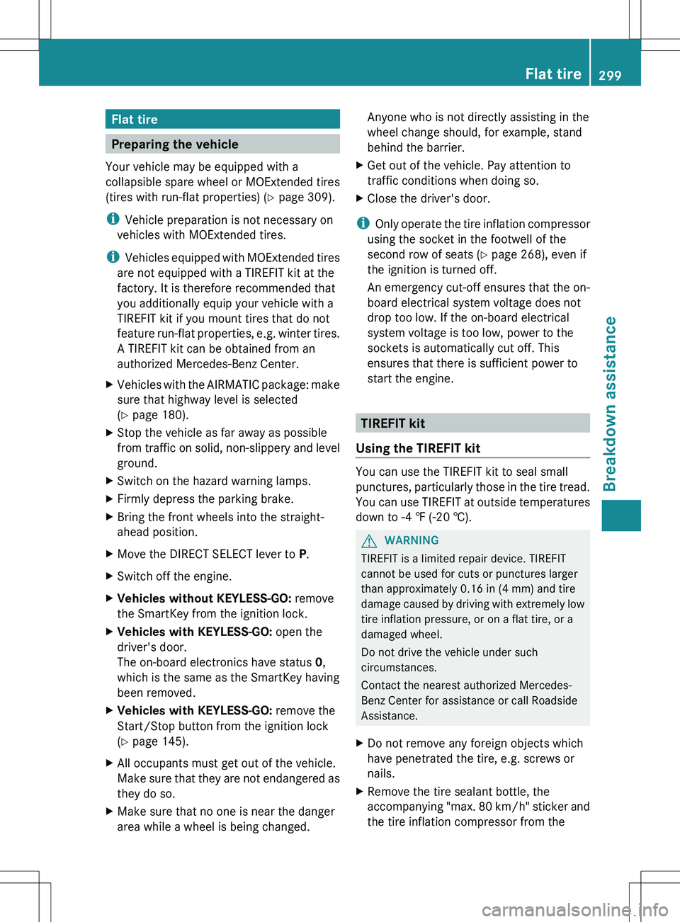
( Y page 296).XAffix part : of the sticker within the
driver's field of vision.XAffix part ; of the sticker near the valve
on the wheel with the defective tire.GWARNING
Take care not to allow the contents of TIREFIT
to come in contact with hair, eyes or clothing.
TIREFIT is harmful if inhaled, swallowed or
absorbed through the skin - causes skin, eye
and respiratory irritation.
Any contact with eyes or skin should be
flushed immediately with plenty of water.
If clothing comes in contact with TIREFIT,
change clothing as soon as possible.
In case of allergic reaction or rash, consult a
physician immediately.
GWARNING
Keep TIREFIT away from children. If
swallowed, rinse mouth immediately with
plenty of water and drink plenty of water.
Do not induce vomiting.
Consult a doctor immediately.
Keep away from open flame or heat source.
i If TIREFIT leaks out, allow it to dry. It can
then be removed like a layer of film.
If you get TIREFIT on your clothing, have it
cleaned as soon as possible with
perchloroethylene.
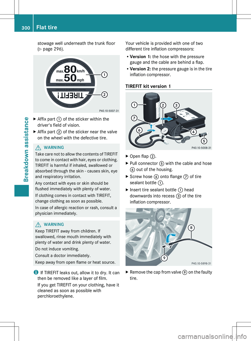
Your vehicle is provided with one of two
different tire inflation compressors:
R Version 1: the hose with the pressure
gauge and the cable are behind a flap.
R Version 2: the pressure gauge is in the tire
inflation compressor.
TIREFIT kit version 1XOpen flap ;.XPull connector A with the cable and hose
B out of the housing.XScrew hose B onto flange C of tire
sealant bottle :.XInsert tire sealant bottle : head
downwards into recess = of the tire
inflation compressor.XRemove the cap from valve E on the faulty
tire.300Flat tireBreakdown assistance
Page 303 of 368
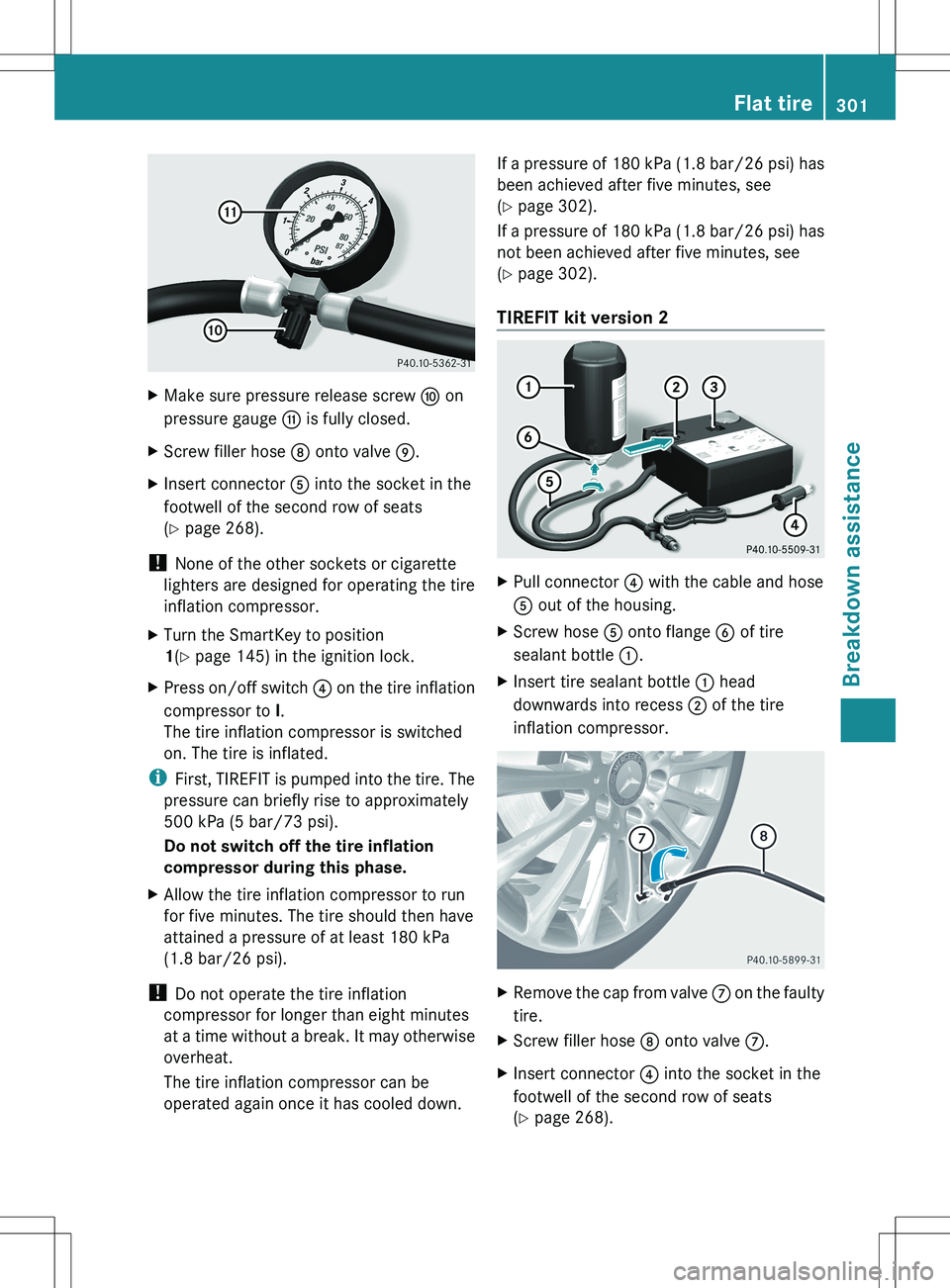
XMake sure pressure release screw F on
pressure gauge G is fully closed.XScrew filler hose D onto valve E.XInsert connector A into the socket in the
footwell of the second row of seats
( Y page 268).
!
None of the other sockets or cigarette
lighters are designed for operating the tire
inflation compressor.
XTurn the SmartKey to position
1 (Y page 145) in the ignition lock.XPress on/off switch ? on the tire inflation
compressor to I.
The tire inflation compressor is switched
on. The tire is inflated.
i First, TIREFIT is pumped into the tire. The
pressure can briefly rise to approximately
500 kPa (5 bar/73 psi).
Do not switch off the tire inflation
compressor during this phase.
XAllow the tire inflation compressor to run
for five minutes. The tire should then have
attained a pressure of at least 180 kPa
(1.8 bar/26 psi).
! Do not operate the tire inflation
compressor for longer than eight minutes
at a time without a break. It may otherwise
overheat.
The tire inflation compressor can be
operated again once it has cooled down.
If a pressure of 180 kPa (1.8 bar/26 psi) has
been achieved after five minutes, see
( Y page 302).
If a pressure of 180 kPa (1.8 bar/26 psi) has
not been achieved after five minutes, see
( Y page 302).
TIREFIT kit version 2XPull connector ? with the cable and hose
A out of the housing.XScrew hose A onto flange B of tire
sealant bottle :.XInsert tire sealant bottle : head
downwards into recess ; of the tire
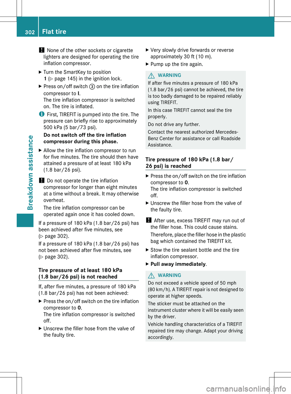
inflation compressor.XRemove the cap from valve C on the faulty
tire.XScrew filler hose D onto valve C.XInsert connector ? into the socket in the
footwell of the second row of seats
( Y page 268).Flat tire301Breakdown assistanceZ
Page 304 of 368
! None of the other sockets or cigarette
lighters are designed for operating the tire
inflation compressor.XTurn the SmartKey to position
1 (Y page 145) in the ignition lock.XPress on/off switch = on the tire inflation
compressor to I.
The tire inflation compressor is switched
on. The tire is inflated.
i First, TIREFIT is pumped into the tire. The
pressure can briefly rise to approximately
500 kPa (5 bar/73 psi).
Do not switch off the tire inflation
compressor during this phase.
XAllow the tire inflation compressor to run
for five minutes. The tire should then have
attained a pressure of at least 180 kPa
(1.8 bar/26 psi).
! Do not operate the tire inflation
compressor for longer than eight minutes
at a time without a break. It may otherwise
overheat.
The tire inflation compressor can be
operated again once it has cooled down.
If a pressure of 180 kPa (1.8 bar/26 psi) has
been achieved after five minutes, see
( Y page 302).
If a pressure of 180 kPa (1.8 bar/26 psi) has
not been achieved after five minutes, see
( Y page 302).
Tire pressure of at least 180 kPa
(1.8 bar/26 psi) is not reached
If, after five minutes, a pressure of 180 kPa
(1.8 bar/26 psi) has not been achieved:
XPress the on/off switch on the tire inflation
compressor to 0.
The tire inflation compressor is switched
off.XUnscrew the filler hose from the valve of
the faulty tire.XVery slowly drive forwards or reverse
approximately 30 ft (10 m).XPump up the tire again.GWARNING
If after five minutes a pressure of 180 kPa
(1.8 bar/26 psi) cannot be achieved, the tire
is too badly damaged to be repaired reliably
using TIREFIT.
In this case TIREFIT cannot seal the tire
properly.
Do not drive any further.
Contact the nearest authorized Mercedes-
Benz Center for assistance or call Roadside
Assistance.
Tire pressure of 180 kPa (1.8 bar/
26 psi) is reached
XPress the on/off switch on the tire inflation
compressor to 0.
The tire inflation compressor is switched
off.XUnscrew the filler hose from the valve of
the faulty tire.
! After use, excess TIREFIT may run out of
the filler hose. This could cause stains.
Therefore, place the filler hose in the plastic
bag which contained the TIREFIT kit.
XStow the tire sealant bottle and the tire
inflation compressor.XPull away immediately .GWARNING
Do not exceed a vehicle speed of 50 mph
(80 km/h ). A TIREFIT repair is not designed to
operate at higher speeds.
The sticker must be attached on the
instrument cluster where it will be easily seen
by the driver.
Vehicle handling characteristics of a TIREFIT
repaired tire may change. Adapt your driving
accordingly.
302Flat tireBreakdown assistance
Page 305 of 368
XStop after driving for approximately ten
minutes and check the tire pressure with
the tire inflation compressor.GWARNING
If tire inflation pressure has fallen below
130 kPa (1.3 bar/26 psi) do not continue to
drive the vehicle.
Park your vehicle safely away from the
roadway and contact the nearest authorized
Mercedes-Benz Center or Roadside
Assistance.
Have the damaged tire replaced.
XCorrect the tire pressure if it is at least
130 kPa (1.3 bar/20 psi) (for the required
values, see the Tire and Loading
Information placard on the driver's side
B-pillar or the tire pressure table inside the
fuel filler flap).XTo increase the tire pressure: switch on
the tire inflation compressor.
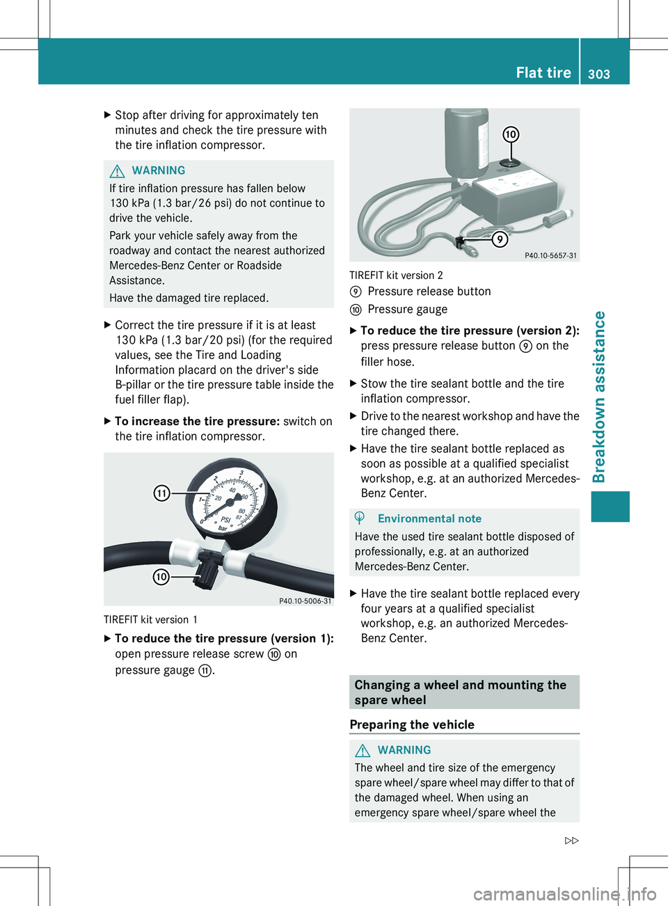
TIREFIT kit version 1
XTo reduce the tire pressure (version 1):
open pressure release screw F on
pressure gauge G.
TIREFIT kit version 2
EPressure release buttonFPressure gaugeXTo reduce the tire pressure (version 2):
press pressure release button E on the
filler hose.XStow the tire sealant bottle and the tire
inflation compressor.XDrive to the nearest workshop and have the
tire changed there.XHave the tire sealant bottle replaced as
soon as possible at a qualified specialist
workshop, e.g. at an authorized Mercedes-
Benz Center.HEnvironmental note
Have the used tire sealant bottle disposed of
professionally, e.g. at an authorized
Mercedes-Benz Center.
XHave the tire sealant bottle replaced every
four years at a qualified specialist
workshop, e.g. an authorized Mercedes-
Benz Center.
Changing a wheel and mounting the
spare wheel
Preparing the vehicle
GWARNING
The wheel and tire size of the emergency
spare wheel/spare wheel may differ to that of
the damaged wheel. When using an
emergency spare wheel/spare wheel the
Flat tire303Breakdown assistanceZ
Page 306 of 368
handling characteristics of the vehicle may
change.
Adapt your style of driving accordingly.
Never operate the vehicle with more than one
emergency spare wheel/spare wheel that
differs in size.
Only use an emergency spare wheel/spare
wheel of a differing size briefly and do not
switch off ESP ®
.
When using an emergency spare wheel, you
must not exceed the maximum speed of
50 mph (80 km/h).GWARNING
Have the emergency spare wheel/spare
wheel replaced with a new wheel as soon as
possible at a qualified specialist workshop
which has the necessary specialist knowledge
and tools to carry out the work required.
Mercedes-Benz recommends that you use an
authorized Mercedes-Benz Center for this
purpose. In particular, work relevant to safety
or on safety-related systems must be carried
out at a qualified specialist workshop.
i Vehicles without a spare wheel/
emergency spare wheel are not equipped
with a tire-change tool kit at the factory. For
more information on which tools are
required to perform a wheel change on your
vehicle, e.g. wheel chock, lug wrench or
alignment bolt, consult an authorized
Mercedes-Benz Center.
XPrepare the vehicle as described
( Y page 299).XIf a trailer is coupled to the vehicle,
uncouple it.XRemove the following items (depending on
the vehicle's equipment) from the stowage
well under the trunk floor:
R the emergency spare wheel 35
R the wheel bolts for the emergency spare
wheel 35
R the jackRthe ratchet wrench
R the lug wrench
R the folding wheel chock
R the alignment bolt
R the tire inflation compressor 35XSecure the vehicle to prevent it from rolling
away.
Securing the vehicle to prevent it from
rolling away
GWARNING
Only jack up the vehicle on level ground or on
slight inclines/declines. The vehicle could
otherwise fall off the jack and injure you or
others.
If your vehicle is equipped with a wheel chock,
it can be found in the vehicle tool kit
( Y page 296).
The folding wheel chock is an additional
securing measure to prevent the vehicle from
rolling away, for example when changing a
wheel.
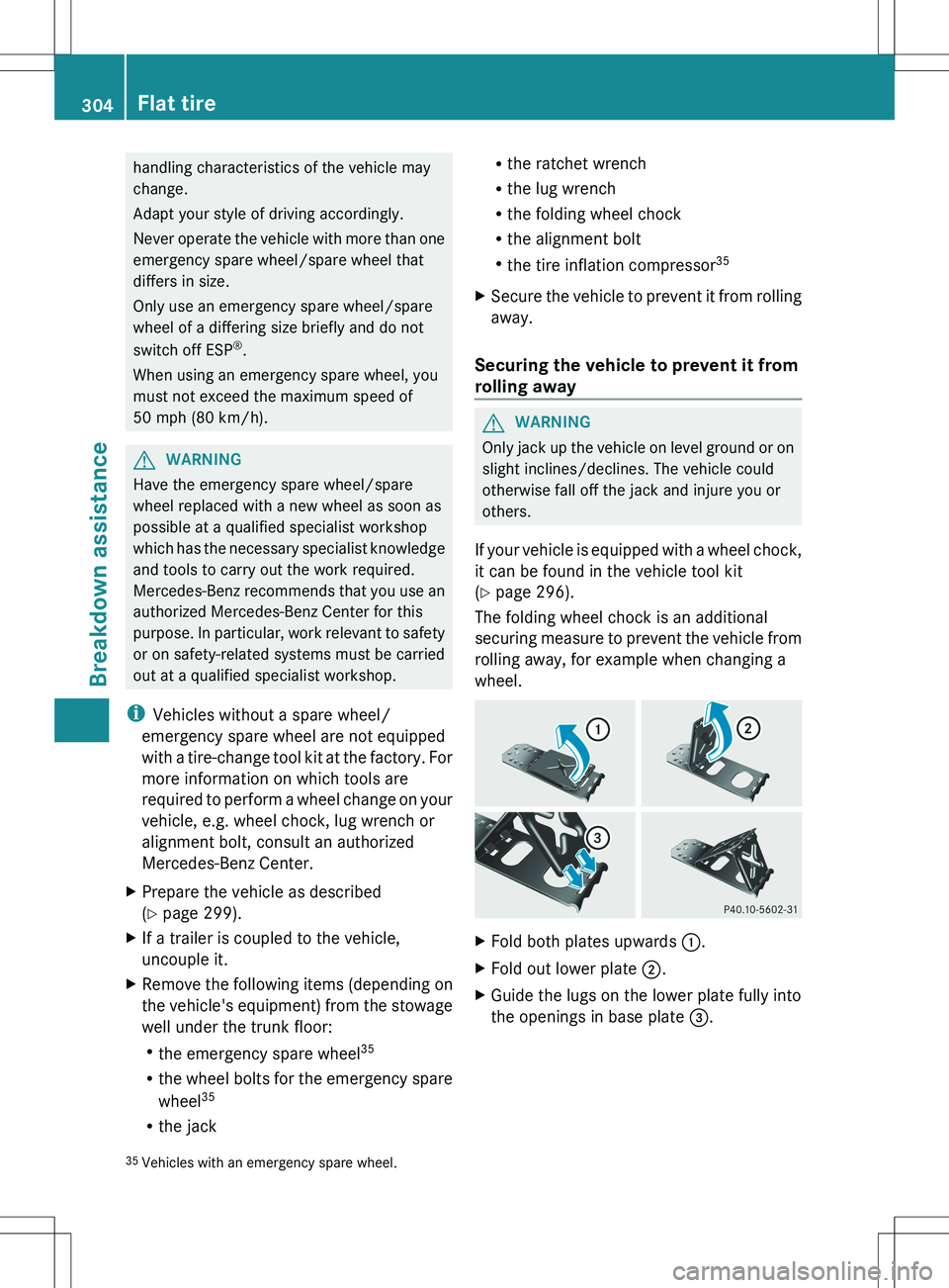
XFold both plates upwards :.XFold out lower plate ;.XGuide the lugs on the lower plate fully into
the openings in base plate =.35
Vehicles with an emergency spare wheel.304Flat tireBreakdown assistance
Page 307 of 368
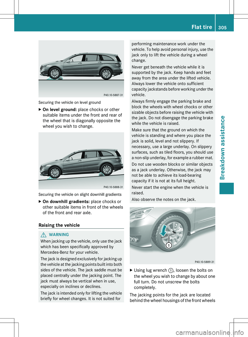
Securing the vehicle on level ground
XOn level ground: place chocks or other
suitable items under the front and rear of
the wheel that is diagonally opposite the
wheel you wish to change.
Securing the vehicle on slight downhill gradients
XOn downhill gradients: place chocks or
other suitable items in front of the wheels
of the front and rear axle.
Raising the vehicle
GWARNING
When jacking up the vehicle, only use the jack
which has been specifically approved by
Mercedes-Benz for your vehicle.
The jack is designed exclusively for jacking up
the vehicle at the jacking points built into both
sides of the vehicle. The jack saddle must be
placed centrally under the jacking point. The
jack must always be vertical when in use,
especially on inclines or declines.
The jack is intended only for lifting the vehicle
briefly for wheel changes. It is not suited for
performing maintenance work under the
vehicle. To help avoid personal injury, use the
jack only to lift the vehicle during a wheel
change.
Never get beneath the vehicle while it is
supported by the jack. Keep hands and feet
away from the area under the lifted vehicle.
Always lower the vehicle onto sufficient
capacity jackstands before working under the
vehicle.
Always firmly engage the parking brake and
block the wheels with wheel chocks or other
sizable objects before raising the vehicle with
the jack. Do not disengage the parking brake
while the vehicle is raised.
Make sure that the ground on which the
vehicle is standing and where you place the
jack is solid, level and not slippery. If
necessary, use a large underlay. On slippery
surfaces, such as tiled floors, you should use
a non-slip underlay, for example a rubber mat.
Do not use wooden blocks or similar objects
as a jack underlay. Otherwise, the jack may
not be able to achieve its load-bearing
capacity if it is not at its full height.
Never start the engine when the vehicle is
raised.
Also observe the notes on the jack.XUsing lug wrench :, loosen the bolts on
the wheel you wish to change by about one
full turn. Do not unscrew the bolts
completely.
The jacking points for the jack are located
behind the wheel housings of the front wheels
Flat tire305Breakdown assistanceZ
Page 308 of 368
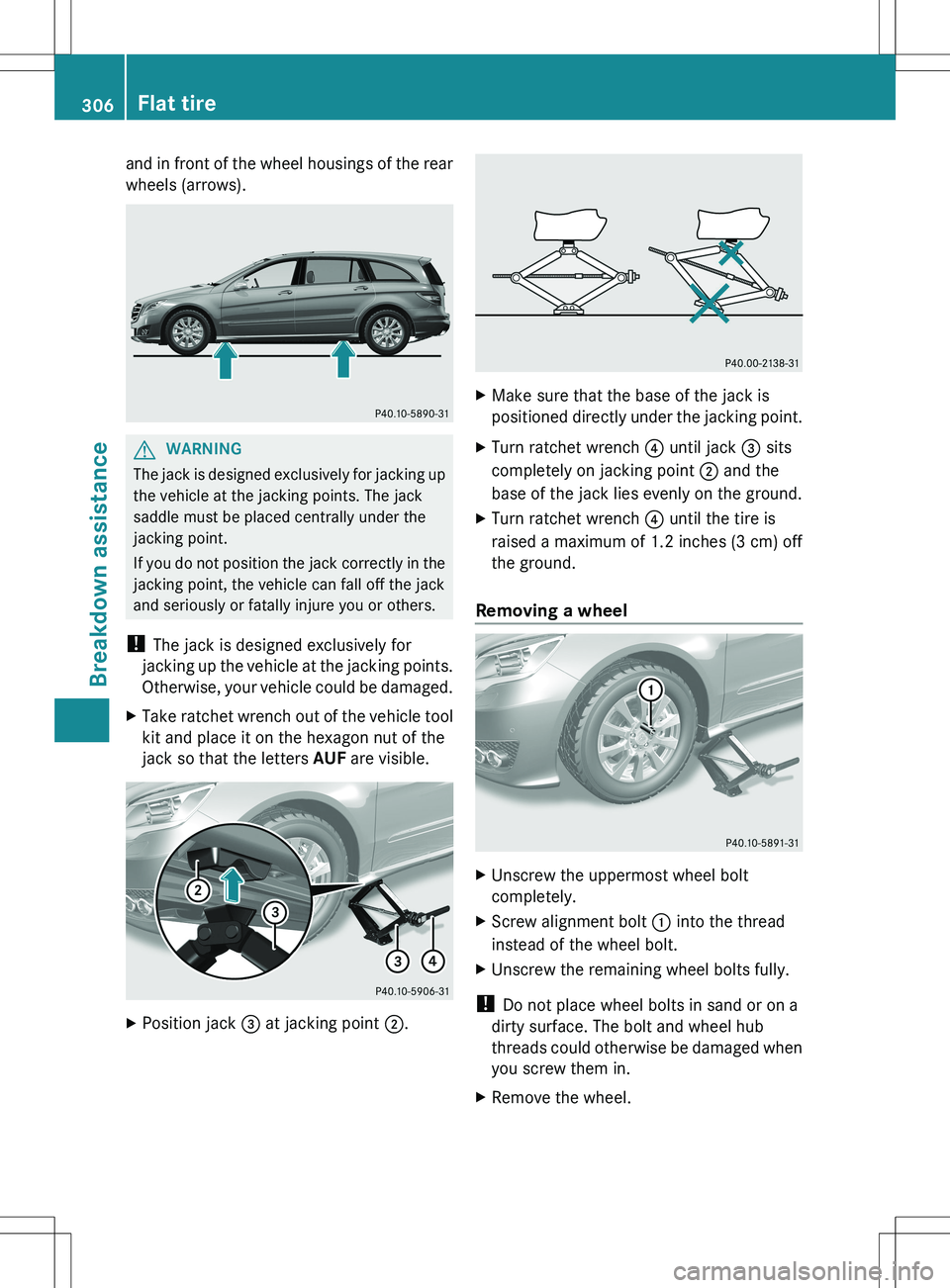
and in front of the wheel housings of the rear
wheels (arrows).GWARNING
The jack is designed exclusively for jacking up
the vehicle at the jacking points. The jack
saddle must be placed centrally under the
jacking point.
If you do not position the jack correctly in the
jacking point, the vehicle can fall off the jack
and seriously or fatally injure you or others.
! The jack is designed exclusively for
jacking up the vehicle at the jacking points.
Otherwise, your vehicle could be damaged.
XTake ratchet wrench out of the vehicle tool
kit and place it on the hexagon nut of the
jack so that the letters AUF are visible.XPosition jack = at jacking point ;.XMake sure that the base of the jack is
positioned directly under the jacking point.XTurn ratchet wrench ? until jack = sits
completely on jacking point ; and the
base of the jack lies evenly on the ground.XTurn ratchet wrench ? until the tire is
raised a maximum of 1.2 inches (3 cm) off
the ground.
Removing a wheel
XUnscrew the uppermost wheel bolt
completely.XScrew alignment bolt : into the thread
instead of the wheel bolt.XUnscrew the remaining wheel bolts fully.
! Do not place wheel bolts in sand or on a
dirty surface. The bolt and wheel hub
threads could otherwise be damaged when
you screw them in.
XRemove the wheel.306Flat tireBreakdown assistance
Page 309 of 368
Mounting a new wheelGWARNING
Always replace wheel bolts that are damaged
or rusted.
Never apply oil or grease to wheel bolts.
Damaged wheel hub threads should be
repaired immediately. Do not continue to
drive under these circumstances! Contact an
authorized Mercedes-Benz Center or call
Roadside Assistance.
Incorrect wheel bolts or improperly tightened
wheel bolts can cause the wheel to come off.
This could cause an accident. Make sure to
use the correct wheel bolts.
GWARNING
Only use genuine Mercedes-Benz wheel bolts.
Other wheel bolts may come loose.
Do not tighten the wheel bolts when the
vehicle is raised. Otherwise, the vehicle could
fall off the jack.
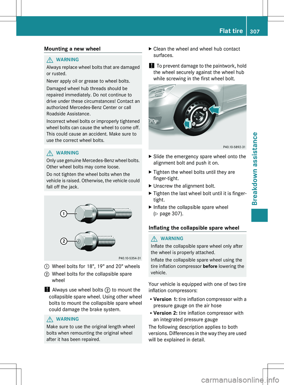
:Wheel bolts for 18", 19" and 20" wheels2Wheel bolts for the collapsible spare
wheel
! Always use wheel bolts ; to mount the
collapsible spare wheel. Using other wheel
bolts to mount the collapsible spare wheel
could damage the brake system.
GWARNING
Make sure to use the original length wheel
bolts when remounting the original wheel
after it has been repaired.
XClean the wheel and wheel hub contact
surfaces.
! To prevent damage to the paintwork, hold
the wheel securely against the wheel hub
while screwing in the first wheel bolt.
XSlide the emergency spare wheel onto the
alignment bolt and push it on.XTighten the wheel bolts until they are
finger-tight.XUnscrew the alignment bolt.XTighten the last wheel bolt until it is finger-
tight.XInflate the collapsible spare wheel
( Y page 307).
Inflating the collapsible spare wheel
GWARNING
Inflate the collapsible spare wheel only after
the wheel is properly attached.
Inflate the collapsible spare wheel using the
tire inflation compressor before lowering the
vehicle.
Your vehicle is equipped with one of two tire
inflation compressors:
R Version 1: tire inflation compressor with a
pressure gauge on the air hose
R Version 2: tire inflation compressor with
an integrated pressure gauge
The following description applies to both
versions. Differences in the way they are used
will be explained in detail.
Flat tire307Breakdown assistanceZ
Page 310 of 368
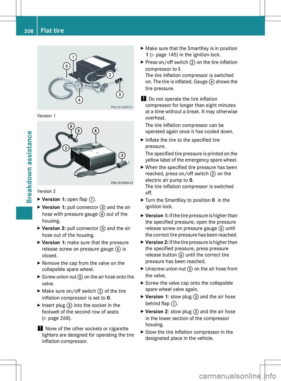
Version 1
Version 2
XVersion 1: open flap :.XVersion 1: pull connector = and the air
hose with pressure gauge ? out of the
housing.XVersion 2: pull connector = and the air
hose out of the housing.XVersion 1: make sure that the pressure
release screw on pressure gauge ? is
closed.XRemove the cap from the valve on the
collapsible spare wheel.XScrew union nut A on the air hose onto the
valve.XMake sure on/off switch ; of the tire
inflation compressor is set to 0.XInsert plug 3 into the socket in the
footwell of the second row of seats
( Y page 268).
!
None of the other sockets or cigarette
lighters are designed for operating the tire
inflation compressor.
XMake sure that the SmartKey is in position
1 (Y page 145) in the ignition lock.XPress on/off switch ; on the tire inflation
compressor to I.
The tire inflation compressor is switched
on. The tire is inflated. Gauge ? shows the
tire pressure.
! Do not operate the tire inflation
compressor for longer than eight minutes
at a time without a break. It may otherwise
overheat.
The tire inflation compressor can be
operated again once it has cooled down.
XInflate the tire to the specified tire
pressure.
The specified tire pressure is printed on the
yellow label of the emergency spare wheel.XWhen the specified tire pressure has been
reached, press on/off switch 2 on the
electric air pump to 0.
The tire inflation compressor is switched
off.XTurn the SmartKey to position 0 in the
ignition lock.XVersion 1: if the tire pressure is higher than
the specified pressure, open the pressure
release screw on pressure gauge 4 until
the correct tire pressure has been reached.XVersion 2: if the tire pressure is higher than
the specified pressure, press pressure
release button 6 until the correct tire
pressure has been reached.XUnscrew union nut A on the air hose from
the valve.XScrew the valve cap onto the collapsible
spare wheel valve again.XVersion 1 : stow plug = and the air hose
behind flap :.XVersion 2 : stow plug = and the air hose
in the lower section of the compressor
housing.XStow the tire inflation compressor in the
designated place in the vehicle.308Flat tireBreakdown assistance