MERCEDES-BENZ S-CLASS CABRIOLET 2018 Owner's Manual
Manufacturer: MERCEDES-BENZ, Model Year: 2018, Model line: S-CLASS CABRIOLET, Model: MERCEDES-BENZ S-CLASS CABRIOLET 2018Pages: 502, PDF Size: 6.27 MB
Page 381 of 502
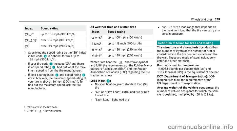
IndexS peedrating
ZR...Y
1up to186mp h(3 00 km/h)
ZR...(..Y)
1ove r18 6mp h(3 00 km/h)
ZR
1ove r14 9mp h (240 km/h)
RSpecifying the speed rating as the "ZR" index
in tire code 4is optional for tires up to
18 6mp h(3 00 km/h).
RIfyo ur tire co de4 includes "ZR"andthere
is no speed rating 7,find out what the max‐
imum speed is from the tire manufacturer.
RIf load-bearing index 6and speed rating 7
are in brac kets, the maximum speed rating of
yo ur tire isabo ve186mp h (300 km/h). To
fi nd out the maximum speed, ask the tire
manufacturer. All-weather tires and winter tires
Inde
xS peedrating
Q M+S
2up to100mp h (160 km/h)
T M+S
2up to118mp h(190 km/h)
H M+S
2up to130mp h (2 10km/h)
V M+S
2up to149mp h (240 km/h)
Winter tires bear thei snowflake symbol
and fulfill therequ irements of theRu bber Manu‐
fa cturers Association (RMA) and theRu bber
Association of Canada (RAC) rega rding the tire
traction on sno w.
Load index 8
:RNo specification given: standard load (SL)
tire
R"XL" or "Extra Load": extra load tire or rein‐
fo rc ed tire
R"Light Load": light load tire
R"C", "D", "E": a load range that depends on
th e maximum load that the tire can car ryat a
cer tain pressure
Definition of termsfo r tires and loading
Ti re stru ctureand characteristics: describes
th e number of la yers or the number of rubber-
coated belts in the tire conta ct surface and the
tire wall. These are made of steel, nylon, poly‐
es ter and other materials.
Bar: metric unit for tire pressure .
14 .5038 pounds per square inch (psi) and
10 0 kilopascal (kPa) is the equivalent of one bar.
DOT (Department of Transport ation):DOT-
mar ked tires fulfill therequ irements of the
US Department of Transpor tatio n.
Av erage weight of theve hicle occupants: the
number of vehicle occupants for which th eve hi‐
cle is designed, multiplied by150 lb (68 kg).
1"ZR" stated in the tire code.2Or "M+S i"for winter tires
Wheels and tires 37
9
Page 382 of 502
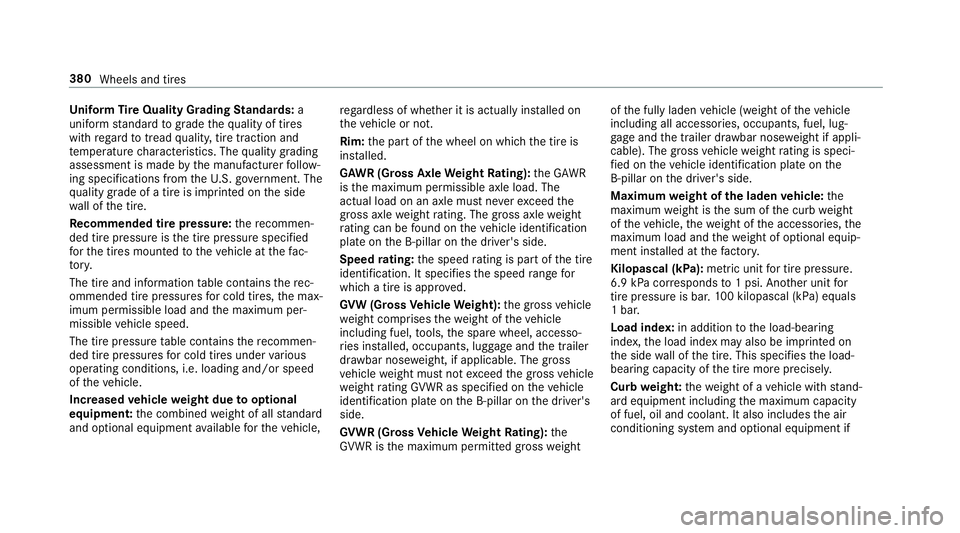
Uniform Tire Quality Grading Standards: a
uniform standard tograde thequ ality of tires
with rega rd totread quality, tire traction and
te mp erature characteristics. The quality grading
assessment is made bythe manufacturer follow‐
ing specifications from theU. S. go vernment. The
qu ality grade of a tire is imprinted on the side
wa ll of the tire.
Re commended tire pressure :th ere commen‐
ded tire pressure is the tire pressure specified
fo rth e tires mounted totheve hicle at thefa c‐
to ry.
The tire and information table conta insthere c‐
ommended tire pressures for cold tires, the max‐
imum permissible load and the maximum per‐
missible vehicle speed.
The tire pressure table conta insthere commen‐
ded tire pressures for cold tires under various
operating conditions, i.e. loading and/or speed
of theve hicle.
Increased vehicle weight due tooptional
equipment: the combined weight of all standard
and optional equipment available forth eve hicle, re
ga rdless of whe ther it is actually ins talled on
th eve hicle or not.
Rim: the part of the wheel on which the tire is
ins talled.
GA WR (Gross Axle Weight Rating): the GAWR
is the maximum permissible axle load. The
actual load on an axle must ne verexc eed the
gros s axle weight rating. The gross axle
weight
ra ti
ng can be found on theve hicle identification
plate on the B‑pillar on the driver's side.
Speed rating: the speed rating is pa rtof the tire
identification. It specifies the speed range for
which a tire is appr oved.
GV W (Gross Vehicle Weight): the gross vehicle
we ight comprises thewe ight of theve hicle
including fuel, tools, the spare wheel, accesso‐
ri es ins talled, occupants, luggage and the trailer
dr aw bar nose weight, if applicable. The gross
ve hicle weight must not exceed the gross vehicle
we ight rating GVWR as specified on theve hicle
identification plate on the B‑pillar on the driver's
side.
GV WR (Gross Vehicle Weight Rating): the
GV WR is the maximum permitted gross weight of
the fully laden vehicle (weight of theve hicle
including all accessories, occupants, fuel, lug‐
ga ge and the trailer dr awbar nose weight if appli‐
cable). The grossve hicle weight rating is speci‐
fi ed on theve hicle identification plate on the
B‑pillar on the driver's side.
Maximum weight of the laden vehicle: the
maximum weight is the sum of the curb weight
of theve hicle, thewe ight of the accessories, the
maximum load and thewe ight of optional equip‐
ment ins talled at thefa ctor y.
Kilopascal (kPa): metricunit for tire pressure .
6.9 kPa cor responds to1 psi. Ano ther unit for
tire pressure is bar.10
0 ki
lopascal (kPa) equals
1 bar.
Load index: in additiontothe load-bearing
index, the load index may also be imprinted on
th e side wall of the tire. This specifies the load-
bearing capacity of the tire more precisel y.
Curb weight: thewe ight of a vehicle with stand‐
ard equipment including the maximum capacity
of fuel, oil and coolant. It also includes the air
conditioning sy stem and optional equipment if
380
Wheels and tires
Page 383 of 502
these are ins talled on theve hicle, but does not
include passengers or luggage.
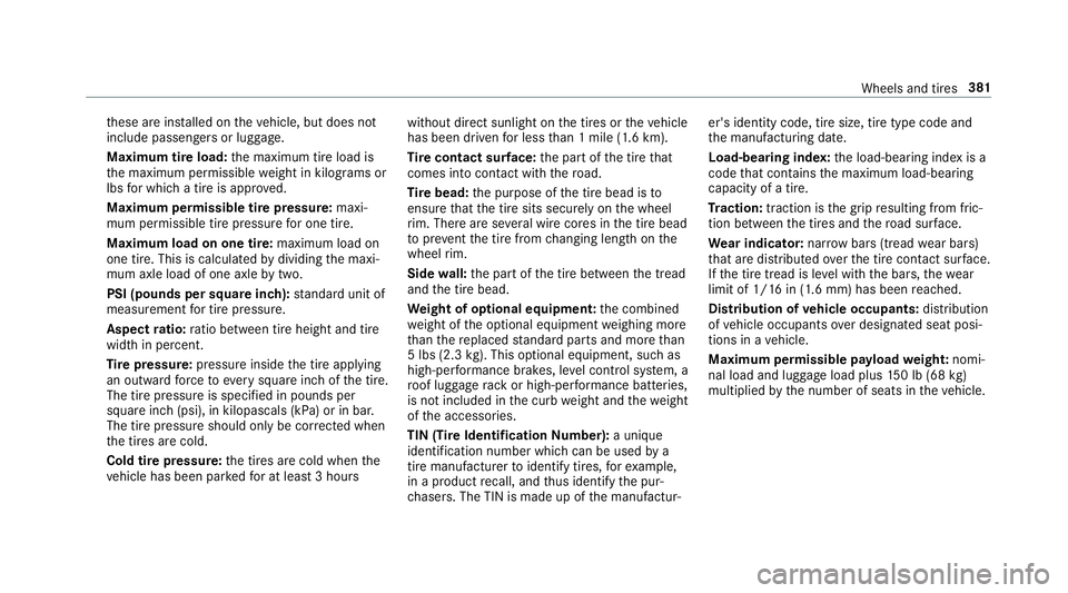
Maximum tire load: the maximum tire load is
th e maximum permissible weight in kilog rams or
lbs for which a tire is appr oved.
Maximum permissible tire pressure: maxi‐
mum permissible tire pressure for one tire.
Maximum load on one tire: maximum load on
one tire. This is calculated bydividing the maxi‐
mum axle load of one axle bytwo.
PSI (pounds per square in ch):standard unit of
measurement for tire pressure .
Aspect ratio: ratio between tire height and tire
width in pe rcent.
Ti re pressure: pressure inside the tire applying
an outward forc eto eve rysquare inch of the tire.
The tire pressure is specified in pounds per
square inch (psi), in kilopascals (kPa) or in bar.
The tire pressure should only be cor rected when
th e tires are cold.
Cold tire pressure: the tires are cold when the
ve hicle has been par kedfo r at least 3 hours without direct sunlight on
the tires or theve hicle
has been driven for less than 1 mile (1.6 km).
Ti re contact sur face: the part of the tire that
comes into con tact wi th thero ad.
Ti re bead: the purpose of the tire bead is to
ensure that the tire sits securely on the wheel
ri m. There are se veral wire cores in the tire bead
to pr
eve ntthe t
ire fromchanging length on the
wheel rim.
Side wall:the part of the tire between the tread
and the tire bead.
We ight of optional equipment: the combined
we ight of the optional equipment weighing more
th an there placed standard parts and more than
5 lbs (2.3 kg).This optional equipment, such as
high-per form ance brakes, le vel control sy stem, a
ro of luggage rack or high-per form ance batte ries,
is not included in the curb weight and thewe ight
of the accessories.
TIN (Tire Identification Number): a unique
identification number which can be used bya
tire manufactu rerto identify tires, forex ample,
in a product recall, and thus identify the pur‐
ch asers. The TIN is made up of the manufactur‐ er's identity code, tire size, tire type code and
th
e manufacturing date.
Load-bearing index: the load-bearing index is a
code that con tains the maximum load-bearing
capacity of a tire.
Tr action: traction is the grip resulting from fric‐
tion between the tires and thero ad sur face.
We ar indicator: narrow bars (tread wear bars)
th at are distributed overth e tire conta ct surface.
If th e tire tread is le vel with the bars, thewe ar
limit of 1/ 16in (1.6 mm) has been reached.
Distribution of vehicle occupants: distribution
of vehicle occupants ov
er design
ated seat posi‐
tions in a vehicle.
Maximum permissible pa yload weight: nomi‐
nal load and luggage load plus 150 lb (68 kg)
multiplied bythe number of seats in theve hicle.
Wheels and tires 381
Page 384 of 502
Changing a wheel
Notes on selecting, installing and replacing
tires
Mercedes -AMG vehicles: observeth e no tes in
th e Supplement. Otherwise, you may not recog‐
nize dangers.
Yo u can ask for information rega rding permitte d
wheel/tire combinations at an authorized
Mercedes-Benz Center.
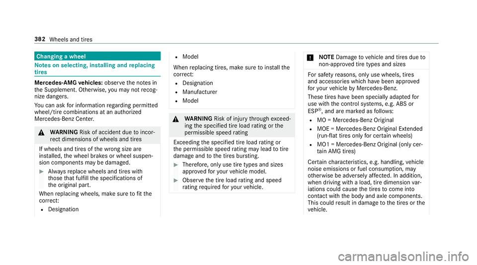
& WARNING Risk of accident due toincor‐
re ct dimensions of wheels and tires
If wheels and tires of the wrong size are
ins talled, the wheel brakes or wheel suspen‐
sion components may be damaged.
#Alw aysre place wheels and tires with
th ose that fulfill the specifications of
th e original part.
When replacing wheels, make sure tofit th e
cor rect:
RDesignation
RModel
When replacing tires, make sure toins tallth e
cor rect:
RDesignation
RManufactu rer
RModel
&
WARNING Risk of injury thro ugh exceed‐
ing the specified tire load rating or the
permissible speed rating
Exceeding the specified tire load rating or
th e permissible speed rating may lead totire
damage andtothe tires bur sting.
#Therefore, only use tire types and sizes
appr ovedfo ryo ur vehicle model.
#Obser vethe tire load rating and speed
ra ting requ ired foryo ur vehicle.
* NO
TEDama getovehicle and tires due to
non-app rove d tire types and sizes
Fo r saf etyre asons, only use wheels, tires
and accessories which havebeen appr oved
fo ryo ur vehicle byMercedes-Benz.
These tires ha vebeen specially adap tedfo r
use with the control sy stems, e.g. ABS or
ESP
®, and are mar ked as follo ws :
RMO = Mercedes-Benz Original
RMOE = Mercedes-Benz Original Extended
(run-flat tires only for cer tain wheels)
RMO1 = Mercedes-Benz Original (only cer‐
tain AMG tires)
Cer tain characteristics, e.g. handling, vehicle
noise emissions or fuel consum ption, may
ot herwise be adversely af fected. In addition,
when driving wi tha load, tire dimension var‐
iations could cause the tires tocome into
contact wi th the body and axle components.
This could result in damage tothe tires or the
ve hicle.
382
Wheels and tires
Page 385 of 502
Only use tires, wheels or accessoriestested
and appr ovedby Mercedes-Benz.
* NO
TERisk todriving saf etyfrom retrea‐
ded tires
Re treaded tires are nei ther tested nor recom‐
mended byMercedes-Benz, since pr evious
damage cannot alw ays be de tected on
re treaded tires.
Fo rth is reason driving saf etycanno tbe guar ‐
anteed.
#Do no tuse used ti res if you ha veno
information about their pr evious usage.
* NO
TEPossible damage towheels or tires
when driving over obs tacles
Large wheels ha vea lo wer tire section wid th.
The lo werth e tire section width, the greater
is therisk of damage towheels or tires when
driving over obs tacles.
#Av oid obs tacles or drive part icularly
carefully.
* NO
TEDama getoelectronic component
parts from the use of tire-mounting tools
Ve hicles with a tire pressure monitoring
sy stem: Electronic component parts are
located in the wheel. Tire -mounting tools
should not be used in the area of theva lve.
This could otherwise damage the electronic
component parts.
#Ha ve the tires changed at a qualified
specialist workshop onl y.
*NO
TEDama getosummer tires at low
ambient temp eratures
Using summer tires at very low ambient tem‐
peratures can cause crac kstoform ,th ereby
damaging the tires permanentl y.
#Attemp eratures below 45 °F (7 °C) use
M+S tires.
Ac cessory part sth at are not appr ovedfo ryo ur
ve hicle byMercedes-Benz or are not being used
cor rectly can impair the operating saf ety. Before purc
hasing and using non-appr oved
accessori es, visit a qualified specialist workshop
and enquire about:
RSuitability
RLegal stipulations
RFa ctory recommendations
&
WARNING Risk of accident wi thhigh
per form ance tires
The special tire tread in combination with the
optimized tire compound means that therisk
of skidding or hydroplaning on wetro ads is
inc reased.
In addition, the tire grip is greatly reduced at
a low outside temp erature and tire running
te mp erature.
#Switch on the ESP®and adapt your
dr ivin gst yle accordingly.
#Use M+S tire at outside temp eratures
of less than 10 °C (50 °F).
Wheels and tires 383
Page 386 of 502
Observethefo llowing when selecting, ins talling
and replacing tires:
ROnly use tires and wheels of the same type
(summer tires, winter tires, MOEx tended
tires) and the same make.
ROnly ins tall wheels of the same size on one
axle (left and right).
It is only permissible toins tall a dif fere nt
wheel size in theeve nt of a flat tire in order
to drive tothe specialist workshop.
ROnly ins tall tires of the cor rect size onto the
wheels.
RVe hicles with a tire pressure monitoring
sy stem: all mounte d wheels must be equip‐
ped with functioning sensors forth e tire
pressure monitoring sy stem.
RAt temp eratures below 45 °F (7 °C), use win‐
te r tires or all-season tires mar ked M+S for
all wheels.
Wi nter tires bearing thei snowflake sym‐
bol in addition tothe M+S marking pr ovide
th e best possible grip in wintry road condi‐
tions.
RFo r M+S tires, only use tires with the same
tread.
RObser vethe maximum permissible speed for
th e M+S tires ins talled.
If th is is below theve hicle's maximum speed,
th is must be indicated in an appropriate label
in the driver's field of vision.
RRu n in new tires at moderate speeds forth e
fi rs t 60 miles (100 km).
RRe place the tires af ter six years at the latest,
re ga rdless of wear.
RWhen replacing with tires that do not fea‐
ture run-flat characteristics: vehicles with
MOExtended tires are not equipped with a
TIREFIT kit at thefa ctor y.Equip theve hicle
with a TIREFIT kit af terre placing with tires
th at do not feature run-flat characteristics,
e.g. winter tires.
Fo r more information on wheels and tires, con‐
ta ct a qualified specialist workshop.
Be sure toalso observ eth efo llowing fur ther
re lated subjects:
RNo tes on tire pressure (→page 364)
RTire and Loading Info rmation placard
(→page 370)
RTire size designation, load-beari ng capacity,
speed rating and load ind ex(→page 377)
RTire pressure table (→page 365)
Note s onrotating wheels
&
WARNING Risk of injury thro ugh dif fer‐
ent wheel sizes
Inter changing the front and rear wheels if the
wheels or tires ha vediffere nt dimensions
may se verely impair the driving characteris‐
tics.
The wheel brakes or wheel suspension com‐
ponents may also be damaged.
#Ro tate front and rear wheels only ifth e
wheels and tires are of the same dimen‐
sions.
384 Wheels and tires
Page 387 of 502
Thewear patte rns on the front and rear wheels
dif fer:
RFr ont wheels wear more on the shoulder of
th e tire
RRe ar wheels wear more in the center of the
tire
On vehicles that ha vethe same size front and
re ar wheels, rotat eth e wheels according tothe
inter vals in the tire manufacturer's warranty
book in your vehicle documents. If this is not
av ailable, rotate the tires every
3,000 to6,000 miles (5,000to10,000 km),
depending on thewe ar. Ensure that the direction
of rotation is maintained.
It is impe rative toobser vethe instructions and
saf etyno tes on "Wheel change" when doing so.
Note s onstoring wheels
RAf terre moving wheels, store them in a cool,
dry and preferably dark place.
RPr otect the tires from conta ct withoil, grease
or fuel.
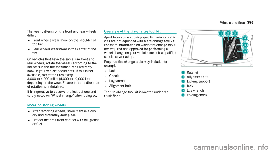
Overview of the tire-chan getool kit
Apart from some countr y-specific variants, vehi‐
cles are not equipped with a tire-change tool kit.
Fo r more information on which tire-changetools
are requ ired and appr ovedfo r per form ing a
wheel change on your vehicle, consult a qualified
specialist workshop.
Re quired tire-change tools may include, for
ex ample:
RJack
RChock
RLu g wrench
RAlignment bolt
The tire-change tool kit is located under the
trunk floor.
1Ra tchet
2Alignment bolt
3Jack ing support
4Jack
5Lu g wrench
6Fo lding chock
Wheels and tires 385
Page 388 of 502
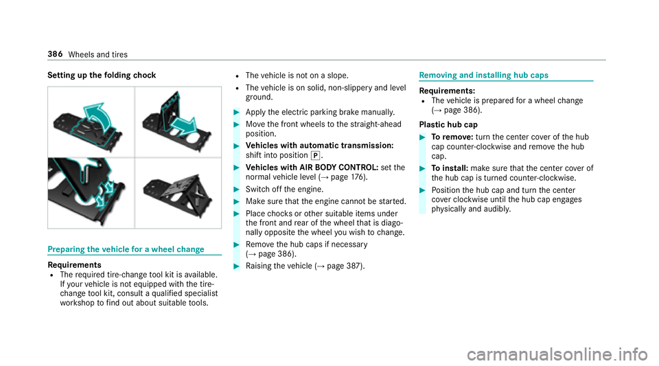
Setting upthefo lding chock
Prepa ring theve hicle for a wheel change
Re quirementsRThe requ ired tire-change tool kit is available.
If yo ur vehicle is not equipped with the tire-
ch ange tool kit, consult a qualified specialist
wo rkshop tofind out about suitable tools.
RThe vehicle is not on a slope.
RThe vehicle is on solid, non-slippery and le vel
ground .
#Applythe electric parking brake manually.
#Mo vethe front wheels tothest ra ight-ahead
position.
#Ve hicles with automatic transmission:
shift into position j.
#Vehicles with AIR BODY CONT ROL:set the
normal vehicle le vel (→page 176).
#Switch off the engine.
#Make sure that the engine cannot bestar ted.
#Place choc ks orother suitable items under
th e front and rear of the wheel that is diago‐
nally opposite the wheel youwish tochange.
#Re mo vethe hub caps if necessary
(→page 386).
#Ra ising theve hicle (→page 387).
Re moving and in stalling hub caps
Re quirements:RThe vehicle is prepared for a wheel change
(→page 386).
Plast ic hub cap
#Toremo ve:turn the center co ver of the hub
cap counter-clockwise and remo vethe hub
cap.
#To install: make sure that the center co ver of
th e hub cap is turned counter-clockwise.
#Po sition the hub cap and turn the center
co ver clockwise until the hub cap engages
ph ysically and audibly.
386
Wheels and tires
Page 389 of 502
Aluminum hub cap
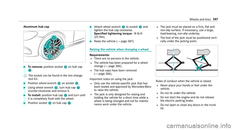
#Toremo ve:position soc ket2 on hub cap
1.
% The soc ket can be found inthe tire-change
to ol kit.
#Po sition wheel wrench 3on soc ket2.
#Using wheel wrench 3, turn hub cap1
counter-clo ckwise and remo veit.
#To install: position hub cap 1and turn until
it is comple tely flush withth e wheel.
#Po sition soc ket2 on hub cap 1.
#Attach wheel wrench 3tosoc ket2 and
tighten the hub cap clockwise.
Specified tightening torq ue: 18lb-ft
(25 Nm).
#Ra ise theve hicle (→page 387).
Ra ising theve hicle when changing a wheel
Re quirements:RThere are no persons in theve hicle.
RThe vehicle has been prepared for a wheel
ch ange (→page 386).
RThe hub caps ha vebeen remo ved
(→page 386).
Impor tant no tes on using the jack:
ROnly use theve hicle-specific jack that has
been tested and appr ovedby Mercedes-Benz
to raise theve hicle.
RThe jack is only designed forra ising and
holding theve hicle for a short time while a
wheel is being changed and not for mainte‐
nance workunder theve hicle.
RThe jack must be placed on a firm ,fl at and
non-slip sur face. If necessar y,use a lar ge,
load-bearing, non-slip underla y.
RThefoot ofthe jack must be positioned verti‐
cally under the jacking point.
Ru les of conduct when theve hicle is raised:
RNe ver place your hands or feet under the
ve hicle.
RDo not lie under theve hicle.
RDo not start the engine and do not release
th e electric parking brake.
RDo not open or close any doors or the trunk
lid.
Wheels and tires 387
Page 390 of 502
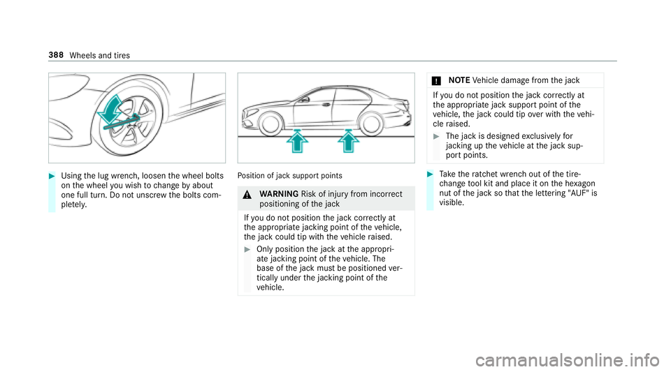
#Usingthe lug wrench, loosen the wheel bolts
on the wheel youwish tochange byabout
one full turn. Do not unscr ewthe bolts com‐
ple tely.Po sition of jack support points
&
WARNING Risk of injury from incorrect
positioning of the jack
If yo u do not position the jack cor rectly at
th e appropriate jacking point of theve hicle,
th e jack could tip with theve hicle raised.
#Only position the jack at the appropri‐
ate jacking point of theve hicle. The
base of the jack must be positioned ver‐
tically under the jacking point of the
ve hicle.
* NO
TEVehicle damage from the jack
Ifyo udo not position the jack cor rectly at
th e appropriate jack support point of the
ve hicle, the jack could tip over with theve hi‐
cle raised.
#The jack is designed exclusively for
jacking up theve hicle at the jack sup‐
port points.
#Ta ke thera tchet wrench out of the tire-
ch ange tool kit and place it on the he xagon
nut of the jack so that the lettering "AUF" is
visible.
388 Wheels and tires