MERCEDES-BENZ SLK ROADSTER 2008 Repair Manual
Manufacturer: MERCEDES-BENZ, Model Year: 2008, Model line: SLK ROADSTER, Model: MERCEDES-BENZ SLK ROADSTER 2008Pages: 273, PDF Size: 4.42 MB
Page 61 of 273
Opening and closing
581
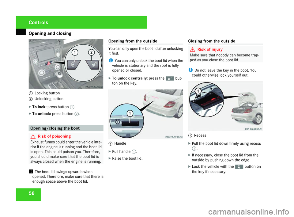
Locking button
2 Unlocking button
X To lock :press button 1.
X To unlock :press button 2. Opening/closing the boot
G
Risk of poisoning
Exhaust fumes could enter the vehicle inte -
rior if the engine is running and the boot lid
is open. This could poison you. Therefore,
you should make sure that the boot lid is
always closed when the engine is running.
! The boot lid swings upwards whe n
opened. Therefore, make sure that there is
enough space above the boot lid. Opening from the outside You can only open the boot lid after unlocking
it first.
i
You can only unlock the boot lid when the
vehicle is stationary and the roof is fully
opened or closed.
X To unlock centrally: press thekbut-
ton on the key. 1
Handle
X Pull handle 1.
X Raise the boot lid. Closing from the outside G
Risk of injury
Make sure that nobody can become trap-
ped as you close the boot lid.
i Do not leave the key in the boot. Yo u
could otherwise lock yourself out. 1
Reces s
X Pull the boot lid down firmly using recess
1 .
X If necessary, close the boot lid from the
outside by pushing down the edge.
X Lock the vehicle with the ‹button on
the key if necessary. Controls
171_AKB; 3; 4, en-GB
vpfaff7,
2007-11-13T10:50:25+01:00 - Seite 58
Page 62 of 273
Seats
59
Locking the boot separately You can lock the boot separately
7
. If you then
unlock the vehicle centrally, the boot remains
locked and cannot be opened.
X Close the boot lid.
X Remove the emergency key element from
the key (Y page 210). $
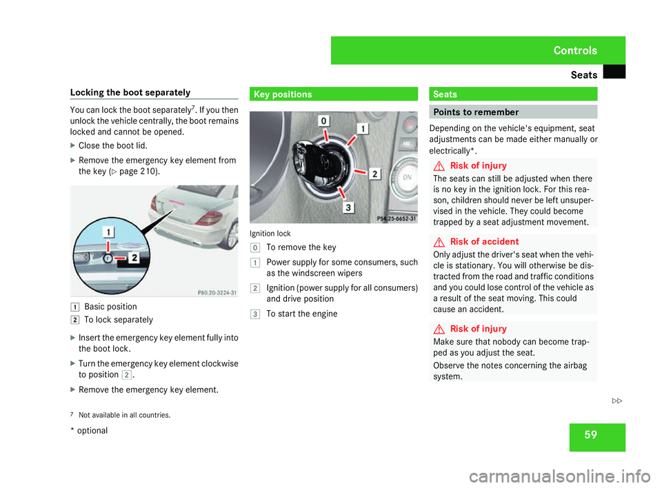
Basic position
% To lock separately
X Insert the emergency key element fully into
the boot lock.
X Turn the emergency key element clockwise
to position %.
X Remove the emergency key element. Key positions
Ignition loc
k
} To remove the key
$ Power supply for some consumers, such
as the windscreen wipers
% Ignition (power supply for all consumers)
and drive positio n
& To start the engine Seats
Points to remember
Depending on the vehicle's equipment, seat
adjustments can be made either manually or
electrically*. G
Risk of injury
The seats can still be adjusted when there
is no key in the ignition lock. For this rea -
son, children should never be left unsuper-
vised in the vehicle. They could become
trapped by a seat adjustment movement. G
Risk of accident
Only adjust the driver's seat when the vehi-
cle is stationary. You will otherwise be dis-
tracted from the road and traffic conditions
and you could lose control of the vehicle as
a result of the seat moving. This could
cause an accident. G
Risk of injury
Make sure that nobody can become trap -
ped as you adjust the seat.
Observe the notes concerning the airbag
system.
7 Not available in all countries. Controls
* optional
171_AKB; 3; 4, en-GB
vpfaff7,
2007-11-13T10:50:25+01:00 - Seite 59 Z
Page 63 of 273
Seats
60 Secure children as recommended; see the
"Children in the vehicle" section.
! When you move the seats, make sure that
there are no objects in the footwell or
behind the seats. Otherwise, you could
damage the seats and the objects.
i The head restraints cannot be removed. Adjusting the seat manually
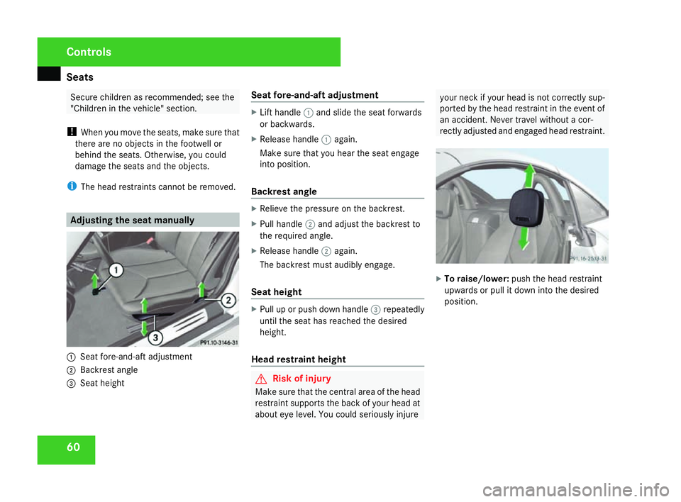
1
Seat fore-and-aft adjustment
2 Backrest angle
3 Seat height Seat fore-and-aft adjustmen
t X
Lift handle 1and slide the seat forwards
or backwards.
X Release handle 1again.
Make sure that you hear the seat engag e
into position .
Backrest angle X
Relieve the pressure on the backrest.
X Pull handle 2and adjust the backrest to
the required angle.
X Release handle 2again.
The backrest must audibly engage.
Seat height X
Pull up or push down handle 3repeatedly
until the seat has reached the desired
height.
Head restraint height G
Risk of injury
Make sure that the central area of the head
restraint supports the back of your head at
about eye level. You could seriously injure your neck if your head is not correctly sup-
ported by the head restraint in the event of
an accident. Never travel without a cor-
rectly adjusted and engaged head restraint. X
To raise/lower: push the head restraint
upwards or pull it down into the desire d
position. Controls
171_AKB; 3; 4, en-GB
vpfaff7,
2007-11-13T10:50:25+01:00 - Seite 60
Page 64 of 273
Seats
61Adjusting the seat electrically*
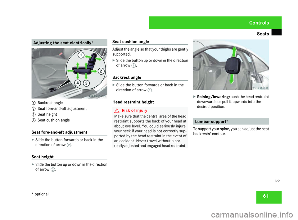
1
Backrest angle
2 Seat fore-and-aft adjustment
3 Seat height
4 Seat cushion angle
Seat fore-and-aft adjustmen tX
Slide the button forwards or back in the
direction of arrow 2.
Seat height X
Slide the button up or down in the directio n
of arrow 3. Seat cushion angle Adjust the angle so that your thighs are gently
supported.
X
Slide the button up or down in the directio n
of arrow 4.
Backrest angle X
Slide the button forwards or back in the
direction of arrow 1.
Head restraint height G
Risk of injury
Make sure that the central area of the head
restraint supports the back of your head at
about eye level. You could seriously injure
your neck if your head is not correctly sup-
ported by the head restraint in the event of
an accident. Never travel without a cor-
rectly adjusted and engaged head restraint. X
Raising/lowering :push the head restraint
downwards or pull it upwards into the
desired position. Lumbar support*
To support your spine, you can adjust the seat
backrests' contour. Controls
* optional
171_AKB; 3; 4, en-GB
vpfaff7,
2007-11-13T10:50:25+01:00 - Seite 61 Z
Page 65 of 273

Seats
621
Upper backrest contour
2 Lower backrest contour
X Make sure that the key is in position 2in
the ignition lock .
X Turn thumbwheels 1and 2until th e
desired backrest contour has been set. AIRSCARF neck-level heating*
The AIRSCARF neck-level heating function
blows warm air around the heads of car occu-
pants. The warm air flows out of the holes in
the head restraints. G
Risk of injury
When AIRSCARF is in operation, very hot ai r
can flow from the vents in the head
restraints. This could cause burns to bare
skin in the immediate vicinity of the vents .
Make sure that you reduce the heater out-
put in time.
The three red indicator lamps in the button
indicate the heating level you have selected. 1
AIRSCARF neck-level heating X
Make sure the key is in position 2in the
ignition lock .
X To activate :press button 1.
Three red indicator lamps in the button light
up. The blower starts up after a preheating
phase of seven seconds.
X Press button 1repeatedly until the
desired heating level is set.
X To switch off: press button1repeatedly
until all the indicator lamps go out.
i The blower continues running for seven
seconds to cool down the heating ele-
ments.
i If the battery voltage is too low, the AIR-
SCARF neck level heating may switch off. Controls
* optional
171_AKB; 3; 4, en-GB
vpfaff7,
2007-11-13T10:50:25+01:00 - Seite 62
Page 66 of 273
Steering wheel
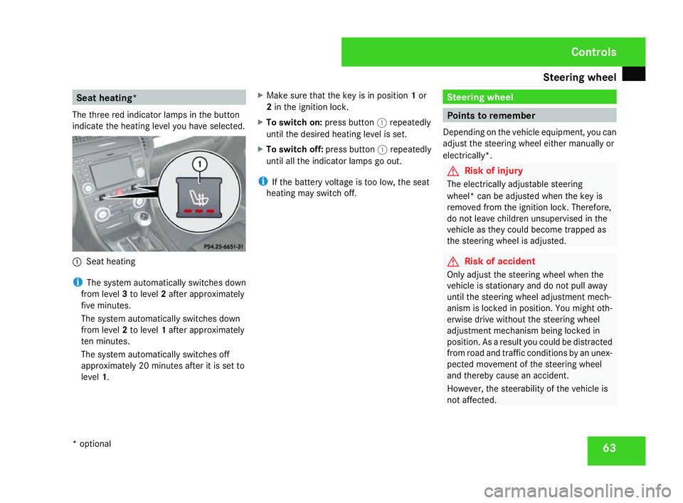
63Seat heating*
The three red indicator lamps in the button
indicate the heating level you have selected. 1
Seat heating
i The system automatically switches down
from level 3to level 2after approximately
five minutes.
The system automatically switches down
from level 2to level 1after approximately
ten minutes.
The system automatically switches off
approximately 20 minutes after it is set to
level 1. X
Make sure that the key is in position 1or
2 in the ignition lock .
X To switch on: press button1repeatedly
until the desired heating level is set.
X To switch off: press button1repeatedly
until all the indicator lamps go out.
i If the battery voltage is too low, the sea t
heating may switch off. Steering wheel
Points to remember
Depending on the vehicle equipment, you can
adjust the steering wheel either manually or
electrically*. G
Risk of injury
The electrically adjustable steering
wheel* can be adjusted when the key is
removed from the ignition lock. Therefore,
do not leave children unsupervised in the
vehicle as they could become trapped as
the steering wheel is adjusted . G
Risk of acciden
t
Only adjust the steering wheel when the
vehicle is stationary and do not pull away
until the steering wheel adjustment mech-
anism is locked in position. You might oth-
erwise drive without the steering whee l
adjustment mechanism being locked in
position. As a result you could be distracted
from road and traffic conditions by an unex -
pected movement of the steering wheel
and thereby cause an accident.
However, the steerability of the vehicle is
not affected. Controls
* optional
171_AKB; 3; 4, en-GB
vpfaff7,
2007-11-13T10:50:25+01:00 - Seite 63
Page 67 of 273

Steering wheel
64
When you adjust the steering wheel, make
sure that:
R
the steering wheel can be reached with
your arms slightly bent
R you can move your legs freely
R you can see all the displays in the instru-
ment cluster clearly Adjusting the steering wheel man-
ually
1
Release handle
2 Steering column height
3 Steering column fore-and-aft adjustment X
Pull handle 1out completely.
The steering column is unlocked.
X Set the desired steering wheel position.
X Push handle 1in completely until it
engages fully.
The steering wheel is locked in position . Adjusting the steering wheel electri-
cally*
1
Steering column height
2 Steering column fore-and-aft adjustment
X Press the lever in the direction of arrow
1 or2 until the steering wheel has
moved into the desired position.
You can find more information under :R
Easy-entry/exit feature (Y page 65)
R Storing settings (Y page 68) Steering wheel heating*
1
To switch on the steering-wheel heating
2 To switch off the steering-wheel heating
3 Indicator lamp
X To switch on or off: make sure that the
key is in position 2in the ignition lock .
X Turn the lever in the direction of arrow 1
or 2 .
Indicator lamp 3comes on or goes out.
i The steering-wheel heating does not
switch off automatically. Controls
* optional
171_AKB; 3; 4, en-GB
vpfaff7,
2007-11-13T10:50:25+01:00 - Seite 64
Page 68 of 273
Mirrors
65Easy-entry/exit feature*
The easy-entry/exit feature makes getting in
and out of your vehicle easier.
The steering wheel swings upwards whe n
you:
R remove the key from the ignition lock
R open the driver's door when the key is in
the ignition lock or in position 1.
The steering wheel is moved automatically to
the position previously set when the key is
inserted into the ignition lock with the driver's
door closed. G
Risk of injury
Make sure that nobody can become trap -
ped when you activate the easy-entry/exit
feature.
If there is a risk of becoming trapped, stop
the adjustment procedure. To halt the pro-
cedure:
R press the steering-column adjustment
switc h
R press one of the memory function posi-
tion buttons
The steering column stops moving immedi-
ately. Never leave children unsupervised in the
vehicle. They could open the driver's door
and thereby unintentionally activate the
easy-entry feature and become trapped.
The most recent position of the steering
wheel is stored when you switch off the igni-
tion or when you store a memory position
( Y page 68).
You can activate and deactivate the easy-
entry/exit feature via the on-board computer
( Y page 106). Mirrors
Rear-view mirror
X Adjust the rear-view mirror by hand so yo u
have a good overview of the traffic condi-
tions.
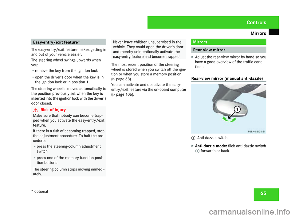
Rear-view mirror (manual anti-dazzle) 1
Anti-dazzle switch
X Anti-dazzle mode: flick anti-dazzle switch
1 forwards or back. Controls
* optional
171_AKB; 3; 4, en-GB
vpfaff7,
2007-11-13T10:50:25+01:00 - Seite 65
Page 69 of 273
Mirrors
66 Exterior mirrors
G
Risk of accident
The exterior mirrors reduce the size of the
image. Objects are actually closer than
they appear. You could misjudge the dis-
tance from vehicles driving behind and
cause an accident, e.g. when changing
lane. For this reason, make sure of the
actual distance from the vehicle driving
behind by glancing over your shoulder .
The convex exterior mirrors give a larger field
of vision.
At low outside temperatures, the exterior mir-
rors are heated automatically.
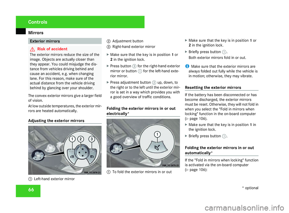
Adjusting the exterior mirrors 1
Left-hand exterior mirror 2
Adjustment button
3 Right-hand exterior mirror
X Make sure that the key is in position 1or
2 in the ignition lock .
X Press button 3for the right-hand exterior
mirror or button 1for the left-hand exte-
rior mirror.
X Press adjustment button 2up, down, to
the right or to the left until the exterior mir -
ror is set in a way which provides you with
a good overview of traffic conditions.
Folding the exterior mirrors in or out
electrically* 1
To fold the exterior mirrors in or out X
Make sure that the key is in position 1or
2 in the ignition lock .
X Briefly press button 1.
Both exterior mirrors fold in or out.
i Make sure that the exterior mirrors are
always folded out fully while the vehicle is
in motion; otherwise, they may vibrate.
Resetting the exterior mirrors If the battery has been disconnected or has
become discharged, the exterior mirrors
must be reset. Otherwise, they will not fold in
when you select the "Fold in mirrors when
locking" function in the on-board computer
( Y page 106).
X Make sure that the key is in position 1in
the ignition lock .
X Briefly press button 1.
Folding the exterior mirrors in or out
automatically* If the "Fold in mirrors when locking" function
is activated via the on-board computer
(
Y page 106): Controls
* optional
171_AKB; 3; 4, en-GB
vpfaff7,
2007-11-13T10:50:25+01:00 - Seite 66
Page 70 of 273
Mirrors
67
R
The exterior mirrors fold in automatically as
soon as you lock the vehicle from the out-
side.
R The exterior mirrors fold out again auto-
matically as soon as you unlock the vehicle
and then open the driver's or front-
passenger door.
i If you have activated this function and fold
in the exterior mirrors using button 1, they
will not be folded out automatically. You
can then only fold out the exterior mirrors
using button 1. Automatic anti-dazzle mirrors
*
The rear-view mirror and the exterior mirror
on the driver's side automatically go into anti-
dazzle mode if the ignition is switched on and
incident light from headlamps strikes the sen-
sor in the rear-view mirror.
The mirrors do not go into anti-dazzle mode if
reverse gear is engaged and the interior light-
ing is switched on. G
Risk of accident
If incident light from the headlamps of othe r
vehicles is prevented from striking the sen-
sor in the rear-view mirror, for instance if the draught stop is fitted, the mirrors' auto-
matic anti-dazzle function will not operate.
Incident light could then dazzle you. This
may prevent you from observing the traffic
conditions, thereby causing an accident. In
this case, adjust the rear-view mirror man-
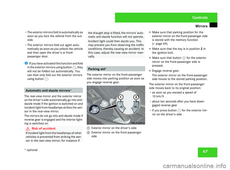
ually. Parking aid*
The exterior mirror on the front-passenger
side moves into parking position as soon as
you engage reverse gear. 1
Exterior mirror on the driver's side
2 Exterior mirror on the front-passenge r
side X
Make sure that parking position for the
exterior mirror on the front-passenger side
is stored with the memory function
(Y page 69).
X Make sure that the key is in position 2in
the ignition lock .
X Make sure that button 2for the exterior
mirror on the front-passenger side is
pressed.
X Engage reverse gear .
The exterior mirror on the front-passenger
side moves to the stored parking position.
The exterior mirror on the front-passenger
side moves back to its original position:
R as soon as you exceed a speed of
10 km/h
R about ten seconds after you have disen -
gaged reverse gear
R if you press button 1for the exterior mir-
ror on the driver's sid e Controls
* optional
171_AKB; 3; 4, en-GB
vpfaff7,
2007-11-13T10:50:25+01:00 - Seite 67