open bonnet MERCEDES-BENZ SLK ROADSTER 2014 Owners Manual
[x] Cancel search | Manufacturer: MERCEDES-BENZ, Model Year: 2014, Model line: SLK ROADSTER, Model: MERCEDES-BENZ SLK ROADSTER 2014Pages: 357, PDF Size: 10.22 MB
Page 8 of 357
ATTENTION ASSIST
Activating/deactivating ................ .212
Display message ............................ 237
Function/notes ............................ .191
ATTENTION ASSIST
see ATTENTION ASSIST
Audio menu (on-board computer) .... 207
Authorised workshop
see Qualified specialist workshop
AUTO lights
Display message ............................ 233
see Lights
Automatic engine start (ECO start/
stop function) ................................... .147
Automatic engine switch-off (ECO
start/stop function) .......................... 146
Automatic headlamp mode .............. 111
Automatic transmission
Accelerator pedal position ............. 153
Automatic drive program .............. .155
Changing gear ............................... 153
Display message ............................ 245
Driving tips ................................... .153
Emergency running mode .............. 158
Kickdown ....................................... 153
Manual drive program .................... 155
Manual drive program (vehicles
with Sports package AMG) ............ 156
Overview ........................................ 152
Problem (fault) ............................... 158
Program selector button ................ 154
Pulling away ................................... 144
Releasing the parking lock man-
ually ............................................... 158
Selector lever ................................ 152
Starting the engine ........................ 144
Steering wheel gearshift paddle s... 154
Transmission position display ........ 152
Transmission positions .................. 153
Automatic transmission emer-
gency running mode ......................... 158B
BAS (Brake Assist System) ................. 61
BAS PLUS (Brake Assist System
PLUS) .................................................... 61 Battery (key)
Checking .......................................... 75
Important safety notes .................... 75
Replacing ......................................... 75
Battery (vehicle)
Charging ........................................ 303
Display message ............................ 235
Important safety notes .................. 300
Jump starting ................................. 304
Overview ........................................ 300
Belt
see Seat belts
Belt tensioner
Activation ......................................... 47
Blind Spot Assist
Activating/deactivating ................. 212
Display message ............................ 239
Notes/function .............................. 194
Bonnet
Active bonnet (pedestrian protec-tion) ............................................... 280
Closing ........................................... 281
Display message ............................ 247
Important safety notes .................. 280
Opening ......................................... 281
Boot
Emergency release .......................... 83
Important safety notes .................... 81
Opening (automatically from out-
side) ................................................. 82
Opening/closing (manually from
outside) ............................................ 82
Overview .......................................... 81
Boot lid
Display message ............................ 247
Opening dimensions ...................... 349
Opening/closing .............................. 81
Boot load (maximum) ........................ 349
Boot separator
Display message ............................ 248
General notes .................................. 89
Opening/closing .............................. 90
Bottle holders .................................... 267
Brake
EBD .................................................. 66
Brake Assist
see BAS (Brake Assist System) Index
5
Page 31 of 357
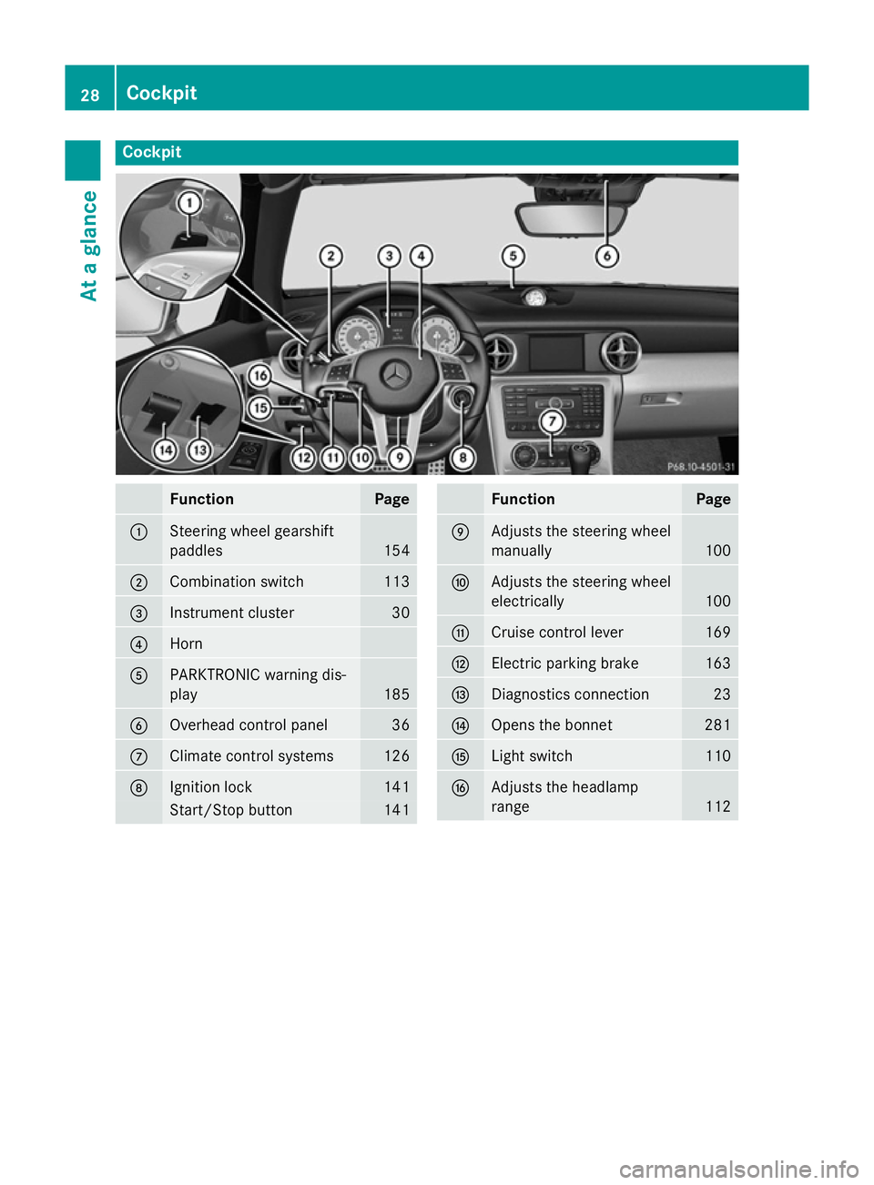
Cockpit
Function Page
:
Steering wheel gearshift
paddles
154
;
Combination switch 113
=
Instrument cluster 30
?
Horn
A
PARKTRONIC warning dis-
play
185
B
Overhead control panel 36
C
Climate control systems 126
D
Ignition lock 141
Start/Stop button 141 Function Page
E
Adjusts the steering wheel
manually
100
F
Adjusts the steering wheel
electrically
100
G
Cruise control lever 169
H
Electric parking brake 163
I
Diagnostics connection 23
J
Opens the bonnet 281
K
Light switch 110
L
Adjusts the headlamp
range
11228
CockpitAt a glance
Page 32 of 357
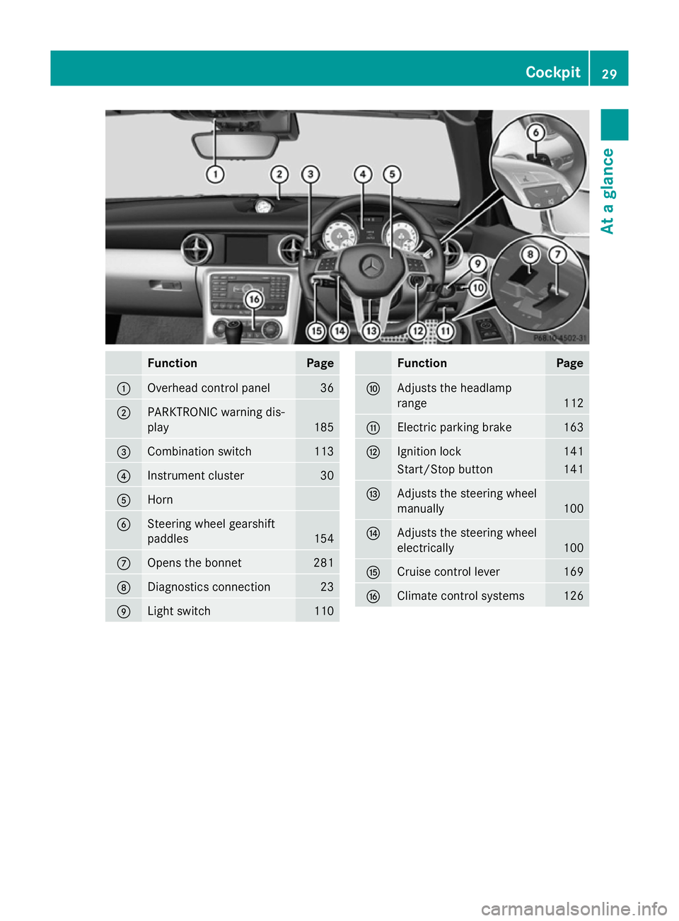
Function Page
:
Overhead control panel 36
;
PARKTRONIC warning dis-
play 185
=
Combination switch 113
?
Instrument cluster 30
A
Horn
B
Steering wheel gearshift
paddles
154
C
Opens the bonnet 281
D
Diagnostics connection 23
E
Light switch 110 Function Page
F
Adjusts the headlamp
range
112
G
Electric parking brake 163
H
Ignition lock 141
Start/Stop button 141
I
Adjusts the steering wheel
manually
100
J
Adjusts the steering wheel
electrically
100
K
Cruise control lever 169
L
Climate control systems 126Cockpit
29At a glance
Page 71 of 357
i
If there is an increased risk of collision,
preventive passenger protection measures
(PRE-SAFE ®
) are activated.
If the risk of collision with the vehicle in front
remains and you do not brake, take evasive
action or accelerate significantly, the vehicle
may perform automatic emergency braking,
up to the point of full brake application. Auto- matic emergency braking is not performed
until immediately prior to an imminent acci-
dent.
You can prevent the intervention of PRE-
SAFE ®
Brake at any time by:
R depressing the accelerator pedal further
R activating kickdown
R releasing the brake pedal
The braking action of PRE-SAFE ®
Brake is
ended automatically if:
R you manoeuvre to avoid the obstacle
R there is no longer any danger of a collision
R there is no longer an obstacle detected in
front of your vehicle Protection against theft
Immobiliser
X To activate with the key: remove the key
from the ignition lock.
X To activate with KEYLESS-GO: switch the
ignition off and open the driver's door.
X To deactivate: switch on the ignition.
The immobiliser prevents your vehicle from
being started without the correct key.
When leaving the vehicle, always take the key with you and lock the vehicle. The engine can
be started by anyone with a valid key that is
left inside the vehicle.
i The immobiliser is always deactivated
when you start the engine. ATA (Anti-Theft Alarm system)
X
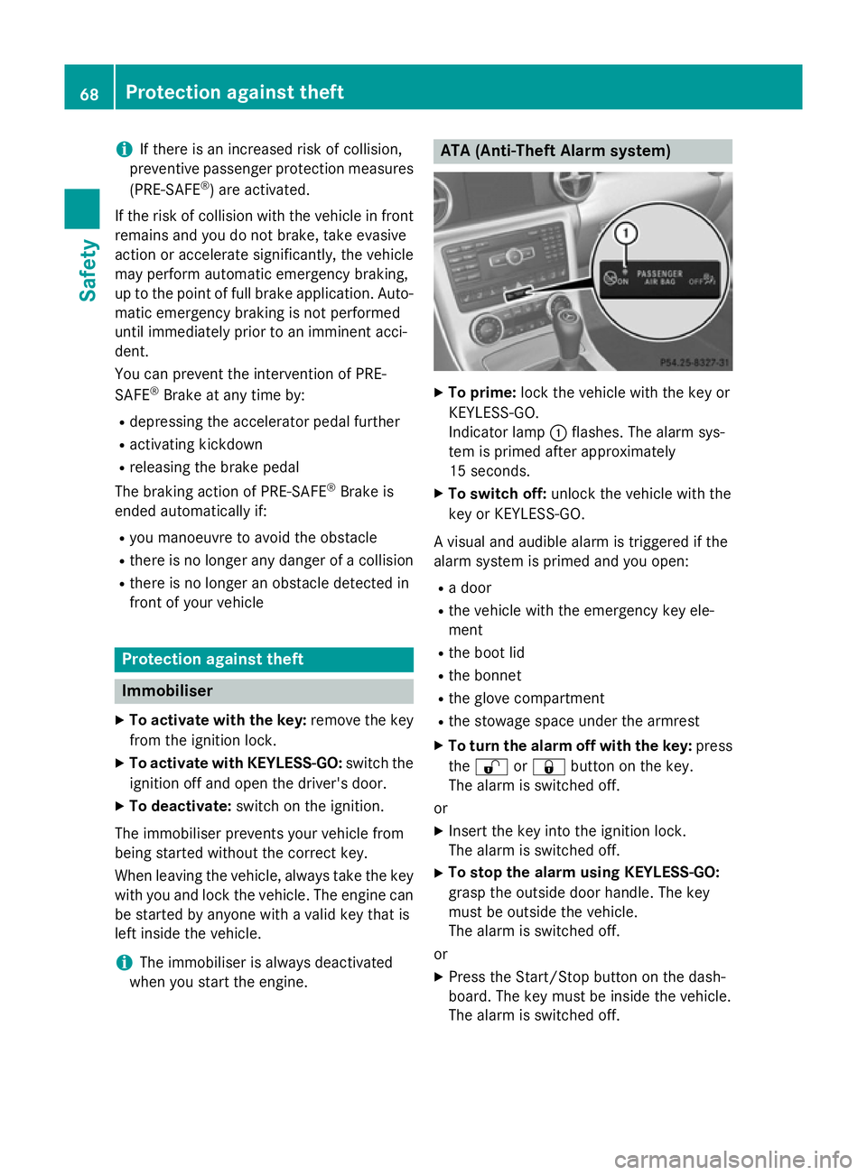
To prime: lock the vehicle with the key or
KEYLESS-GO.
Indicator lamp :flashes. The alarm sys-
tem is primed after approximately
15 seconds.
X To switch off: unlock the vehicle with the
key or KEYLESS-GO.
A visual and audible alarm is triggered if the
alarm system is primed and you open: R a door
R the vehicle with the emergency key ele-
ment
R the boot lid
R the bonnet
R the glove compartment
R the stowage space under the armrest
X To turn the alarm off with the key: press
the % or& button on the key.
The alarm is switched off.
or
X Insert the key into the ignition lock.
The alarm is switched off.
X To stop the alarm using KEYLESS-GO:
grasp the outside door handle. The key
must be outside the vehicle.
The alarm is switched off.
or
X Press the Start/Stop button on the dash-
board. The key must be inside the vehicle.
The alarm is switched off. 68
Protection against theftSafety
Page 122 of 357
X
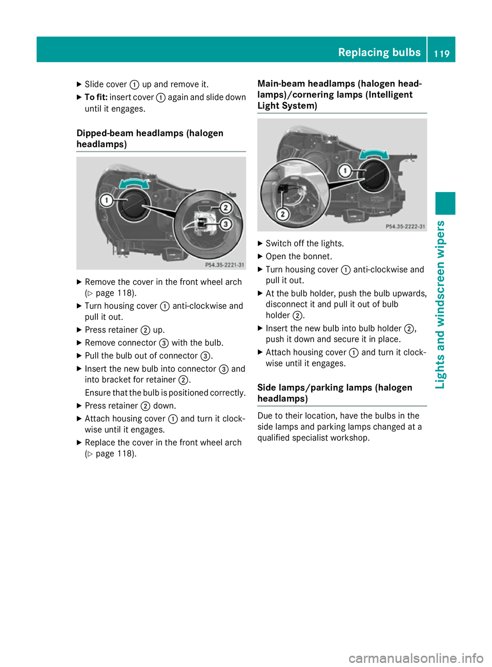
Slide cover :up and remove it.
X To fit: insert cover :again and slide down
until it engages.
Dipped-beam headlamps (halogen
headlamps) X
Remove the cover in the front wheel arch
(Y page 118).
X Turn housing cover :anti-clockwise and
pull it out.
X Press retainer ;up.
X Remove connector =with the bulb.
X Pull the bulb out of connector =.
X Insert the new bulb into connector =and
into bracket for retainer ;.
Ensure that the bulb is positioned correctly.
X Press retainer ;down.
X Attach housing cover :and turn it clock-
wise until it engages.
X Replace the cover in the front wheel arch
(Y page 118). Main-beam headlamps (halogen head-
lamps)/cornering lamps (Intelligent
Light System) X
Switch off the lights.
X Open the bonnet.
X Turn housing cover :anti-clockwise and
pull it out.
X At the bulb holder, push the bulb upwards,
disconnect it and pull it out of bulb
holder ;.
X Insert the new bulb into bulb holder ;,
push it down and secure it in place.
X Attach housing cover :and turn it clock-
wise until it engages.
Side lamps/parking lamps (halogen
headlamps) Due to their location, have the bulbs in the
side lamps and parking lamps changed at a
qualified specialist workshop. Replacing bulbs
119Lights and windscreen wipers Z
Page 123 of 357
Turn signal lamp (halogen headlamps)
X
Switch off the lights.
X Open the bonnet.
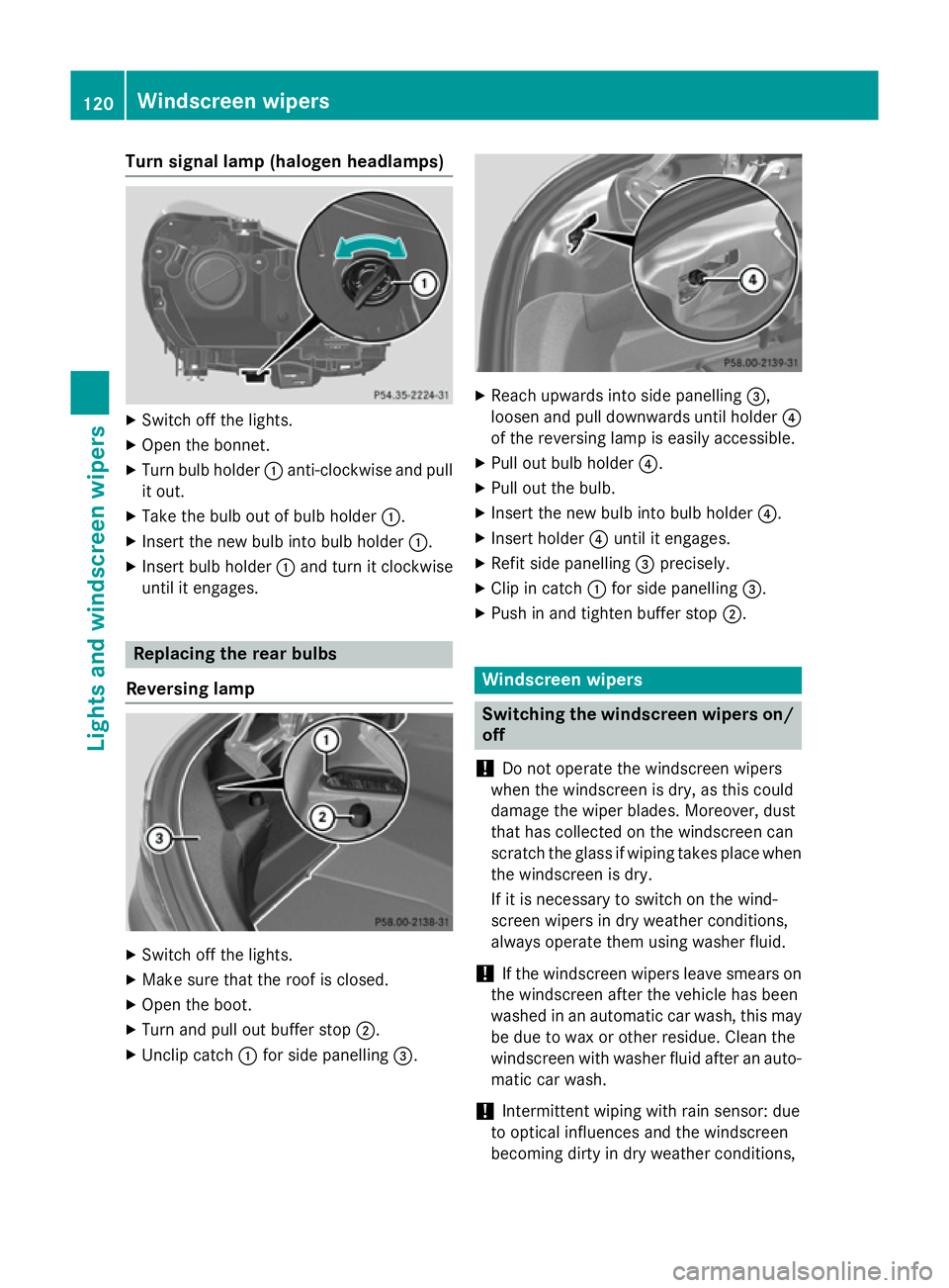
X Turn bulb holder :anti-clockwise and pull
it out.
X Take the bulb out of bulb holder :.
X Insert the new bulb into bulb holder :.
X Insert bulb holder :and turn it clockwise
until it engages. Replacing the rear bulbs
Reversing lamp X
Switch off the lights.
X Make sure that the roof is closed.
X Open the boot.
X Turn and pull out buffer stop ;.
X Unclip catch :for side panelling =. X
Reach upwards into side panelling =,
loosen and pull downwards until holder ?
of the reversing lamp is easily accessible.
X Pull out bulb holder ?.
X Pull out the bulb.
X Insert the new bulb into bulb holder ?.
X Insert holder ?until it engages.
X Refit side panelling =precisely.
X Clip in catch :for side panelling =.
X Push in and tighten buffer stop ;. Windscreen wipers
Switching the windscreen wipers on/
off
! Do not operate the windscreen wipers
when the windscreen is dry, as this could
damage the wiper blades. Moreover, dust
that has collected on the windscreen can
scratch the glass if wiping takes place when the windscreen is dry.
If it is necessary to switch on the wind-
screen wipers in dry weather conditions,
always operate them using washer fluid.
! If the windscreen wipers leave smears on
the windscreen after the vehicle has been
washed in an automatic car wash, this may
be due to wax or other residue. Clean the
windscreen with washer fluid after an auto- matic car wash.
! Intermittent wiping with rain sensor: due
to optical influences and the windscreen
becoming dirty in dry weather conditions, 120
Windscreen
wipersLights and windscreen wipers
Page 124 of 357
the windscreen wipers may be activated
inadvertently. This could damage the wind- screen wiper blades or scratch the wind-
screen.
For this reason, you should always switch
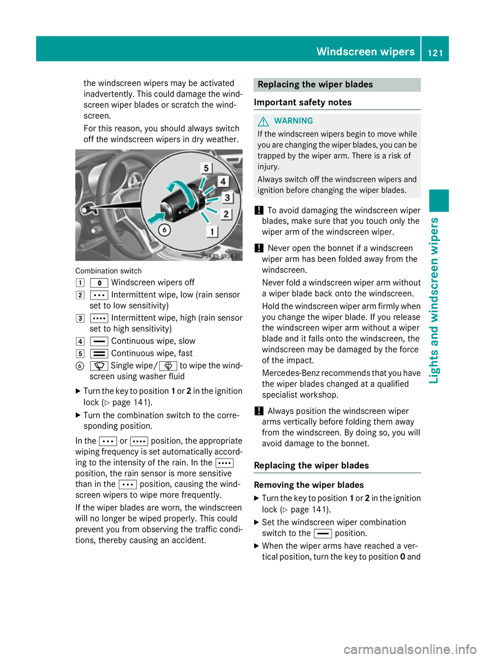
off the windscreen wipers in dry weather. Combination switch
1
$ Windscreen wipers off
2 Ä Intermittent wipe, low (rain sensor
set to low sensitivity)
3 Å Intermittent wipe, high (rain sensor
set to high sensitivity)
4 ° Continuous wipe, slow
5 ¯ Continuous wipe, fast
B í Single wipe/ îto wipe the wind-
screen using washer fluid
X Turn the key to position 1or 2in the ignition
lock (Y page 141).
X Turn the combination switch to the corre-
sponding position.
In the ÄorÅ position, the appropriate
wiping frequency is set automatically accord- ing to the intensity of the rain. In the Å
position, the rain sensor is more sensitive
than in the Äposition, causing the wind-
screen wipers to wipe more frequently.
If the wiper blades are worn, the windscreen
will no longer be wiped properly. This could
prevent you from observing the traffic condi-
tions, thereby causing an accident. Replacing the wiper blades
Important safety notes G
WARNING
If the windscreen wipers begin to move while
you are changing the wiper blades, you can be trapped by the wiper arm. There is a risk of
injury.
Always switch off the windscreen wipers and
ignition before changing the wiper blades.
! To avoid damaging the windscreen wiper
blades, make sure that you touch only the
wiper arm of the windscreen wiper.
! Never open the bonnet if a windscreen
wiper arm has been folded away from the
windscreen.
Never fold a windscreen wiper arm without
a wiper blade back onto the windscreen.
Hold the windscreen wiper arm firmly when you change the wiper blade. If you release
the windscreen wiper arm without a wiper
blade and it falls onto the windscreen, the
windscreen may be damaged by the force
of the impact.
Mercedes-Benz recommends that you havethe wiper blades changed at a qualified
specialist workshop.
! Always position the windscreen wiper
arms vertically before folding them away
from the windscreen. By doing so, you will
avoid damage to the bonnet.
Replacing the wiper blades Removing the wiper blades
X Turn the key to position 1or 2in the ignition
lock (Y page 141).
X Set the windscreen wiper combination
switch to the °position.
X When the wiper arms have reached a ver-
tical position, turn the key to position 0and Windscreen
wipers
121Lights and windscreen wipers Z
Page 139 of 357
This could result in burns in the immediate
vicinity of the air vents. There is a risk of injury.
Reduce the heater output before it becomes
too hot.
In order to ensure the direct flow of fresh air
through the air vents into the vehicle interior, please observe the following notes:
R keep the air inlet grille on the bonnet and in
the engine compartment on the front-
passenger side free of blockages, such as
ice, snow or leaves.
R never cover the vents or ventilation grilles
in the vehicle interior.
i You can move the adjusters for the air
vents vertically or horizontally to set the
direction of the airflow.
i Optimal climate control function is ach-
ieved by opening the air vents fully and set- ting the adjusters to the middle position. Setting the centre air vents
X
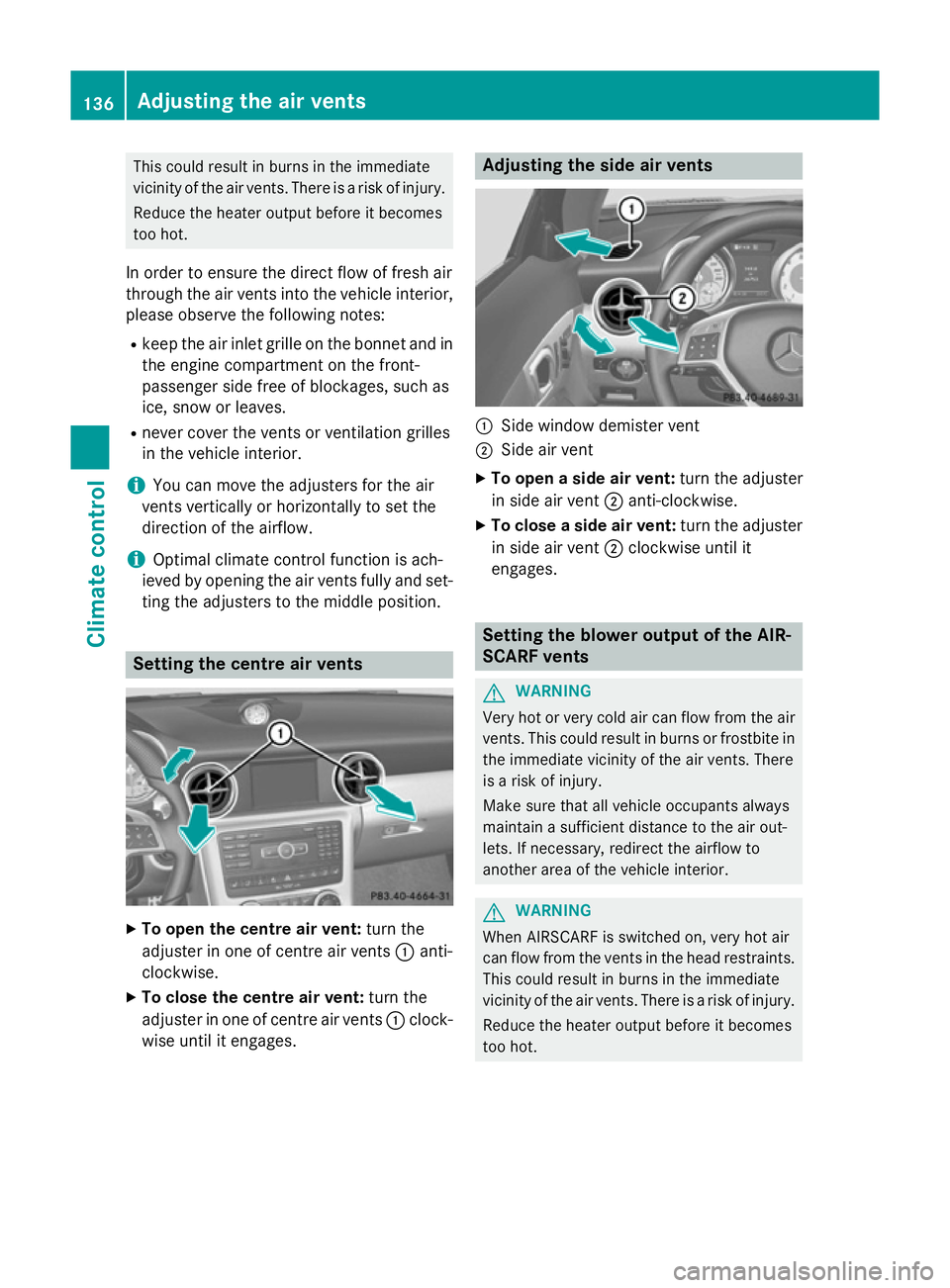
To open the centre air vent: turn the
adjuster in one of centre air vents :anti-
clockwise.
X To close the centre air vent: turn the
adjuster in one of centre air vents :clock-
wise until it engages. Adjusting the side air vents
:
Side window demister vent
; Side air vent
X To open a side air vent: turn the adjuster
in side air vent ;anti-clockwise.
X To close a side air vent: turn the adjuster
in side air vent ;clockwise until it
engages. Setting the blower output of the AIR-
SCARF vents
G
WARNING
Very hot or very cold air can flow from the air vents. This could result in burns or frostbite in the immediate vicinity of the air vents. There
is a risk of injury.
Make sure that all vehicle occupants always
maintain a sufficient distance to the air out-
lets. If necessary, redirect the airflow to
another area of the vehicle interior. G
WARNING
When AIRSCARF is switched on, very hot air
can flow from the vents in the head restraints. This could result in burns in the immediate
vicinity of the air vents. There is a risk of injury.
Reduce the heater output before it becomes
too hot. 136
Adjusting the air ventsClimate control
Page 178 of 357
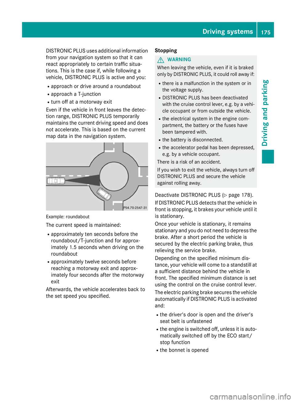
DISTRONIC PLUS uses additional information
from your navigation system so that it can
react appropriately to certain traffic situa-
tions. This is the case if, while following a
vehicle, DISTRONIC PLUS is active and you:
R approach or drive around a roundabout
R approach a T-junction
R turn off at a motorway exit
Even if the vehicle in front leaves the detec-
tion range, DISTRONIC PLUS temporarily
maintains the current driving speed and does not accelerate. This is based on the current
map data in the navigation system. Example: roundabout
The current speed is maintained:
R approximately ten seconds before the
roundabout/T-junction and for approx-
imately 1.5 second s when driving onthe
roundabout
R approximately twelve seconds before
reaching a motorway exit and approx-
imately four seconds after the motorway
exit
Afterwards, the vehicle accelerates back to
the set speed you specified. Stopping G
WARNING
When leaving the vehicle, even if it is braked
only by DISTRONIC PLUS, it could roll away if:
R there is a malfunction in the system or in
the voltage supply.
R DISTRONIC PLUS has been deactivated
with the cruise control lever, e.g. by a vehi- cle occupant or from outside the vehicle.
R the electrical system in the engine com-
partment, the battery or the fuses have
been tampered with.
R the battery is disconnected.
R the accelerator pedal has been depressed,
e.g. by a vehicle occupant.
There is a risk of an accident.
If you wish to exit the vehicle, always turn off
DISTRONIC PLUS and secure the vehicle
against rolling away.
Deactivate DISTRONIC PLUS (Y page 178).
If DISTRONIC PLUS detects that the vehicle in front is stopping, it brakes your vehicle until it
is stationary.
Once your vehicle is stationary, it remains
stationary and you do not need to depress the
brake. After a short period the vehicle is
secured by the electric parking brake, thus
relieving the service brake.
Depending on the specified minimum dis-
tance, your vehicle will come to a standstill at a sufficient distance behind the vehicle in
front. The specified minimum distance is set
using the control on the cruise control lever.
The electric parking brake secures the vehicle
automatically if DISTRONIC PLUS is activated
and:
R the driver's door is open and the driver's
seat belt is unfastened
R the engine is switched off, unless it is auto-
matically switched off by the ECO start/
stop function
R the bonnet is opened Driving systems
175Driving and parking Z
Page 179 of 357
R
a system fault occurs
R the power supply is not sufficient
If the vehicle electronics are malfunctioning,
the multifunction display may also show a
warning message.
Brake immediately Brake immediately
X Immediately depress the brake pedal firmly
until the warning message in the multifunc-
tion display goes out. DISTRONIC PLUS is
deactivated.
Select Park (P)
Select Park (P)
X Shift the transmission to position Pto pre-
vent the vehicle from rolling away.
DISTRONIC PLUS is deactivated. The warn-
ing message in the multifunction display
disappears.
The horn will also sound at regular intervals if DISTRONIC PLUS is activated and you:
R switch the engine off, open the driver's
door and take off your seat belt
R open the bonnet
The sounding of the horn alerts you to the fact
that the vehicle has been parked while DIS-
TRONIC PLUS is still activated. The sound
becomes louder if you attempt to lock the
vehicle. The vehicle is not locked until DIS-
TRONIC PLUS is deactivated.
i If the engine has been switched off, it
cannot be started again until DISTRONIC
PLUS has been deactivated.
Storing the current speed and calling up
the last stored speed G
WARNING
If you call up a stored speed and this is dif-
ferent from the current speed, the vehicle
accelerates or brakes. If you do not know
what the stored speed is, the vehicle may
accelerate or brake unexpectedly. There is a
risk of an accident.
Take the traffic conditions into account
before calling up the stored speed. If you do
not know what the stored speed is, store the
desired speed again. X
Briefly pull the cruise control lever towards
you ?.
X Remove your foot from the accelerator
pedal.
DISTRONIC PLUS is activated. The first
time it is activated, the current speed is
stored. Otherwise, it sets the vehicle cruise
speed to the previously stored value.
Setting a speed Bear in mind that it may take a brief moment
until the vehicle has accelerated or braked to the set speed.
X Press the cruise control lever up :for a
higher speed or down Afor a lower speed.
X Keep the cruise control lever pressed until
the desired speed is reached.
X Release the cruise control lever.
The new speed is stored. DISTRONIC PLUS
is activated and adjusts the vehicle's speed to the new speed stored.
X To adjust the set speed in 1 km/h incre-
ments: briefly press the cruise control
lever up :to the pressure point for a
higher speed, or down Afor a lower speed.
The last speed stored is increased or
reduced.
X To adjust the set speed in 10 km/h
increments: briefly press the cruise con-
trol lever up :past the pressure point for
a higher speed, or down Afor a lower
speed.
The last speed stored is increased or
reduced.
Setting the specified minimum distance You can set the specified minimum distance
for DISTRONIC PLUS by varying the time span between one and two seconds. With this func-
tion, you can set the minimum distance that
DISTRONIC PLUS maintains to the vehicle in
front, dependent on vehicle speed. You can
see this distance in the multifunction display
(Y page 177). 176
Driving systemsDriving and parking