Transmission MERCEDES-BENZ SPRINTER 2005 Service Owner's Manual
[x] Cancel search | Manufacturer: MERCEDES-BENZ, Model Year: 2005, Model line: SPRINTER, Model: MERCEDES-BENZ SPRINTER 2005Pages: 1232, PDF Size: 39.23 MB
Page 113 of 1232
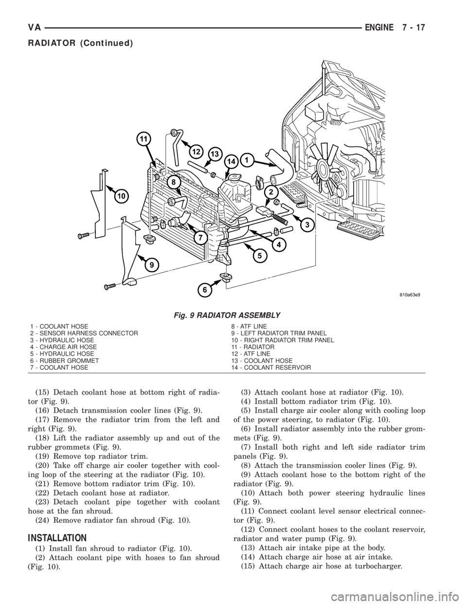
(15) Detach coolant hose at bottom right of radia-
tor (Fig. 9).
(16) Detach transmission cooler lines (Fig. 9).
(17) Remove the radiator trim from the left and
right (Fig. 9).
(18) Lift the radiator assembly up and out of the
rubber grommets (Fig. 9).
(19) Remove top radiator trim.
(20) Take off charge air cooler together with cool-
ing loop of the steering at the radiator (Fig. 10).
(21) Remove bottom radiator trim (Fig. 10).
(22) Detach coolant hose at radiator.
(23) Detach coolant pipe together with coolant
hose at the fan shroud.
(24) Remove radiator fan shroud (Fig. 10).
INSTALLATION
(1) Install fan shroud to radiator (Fig. 10).
(2) Attach coolant pipe with hoses to fan shroud
(Fig. 10).(3) Attach coolant hose at radiator (Fig. 10).
(4) Install bottom radiator trim (Fig. 10).
(5) Install charge air cooler along with cooling loop
of the power steering, to radiator (Fig. 10).
(6) Install radiator assembly into the rubber grom-
mets (Fig. 9).
(7) Install both right and left side radiator trim
panels (Fig. 9).
(8) Attach the transmission cooler lines (Fig. 9).
(9) Attach coolant hose to the bottom right of the
radiator (Fig. 9).
(10) Attach both power steering hydraulic lines
(Fig. 9).
(11) Connect coolant level sensor electrical connec-
tor (Fig. 9).
(12) Connect coolant hoses to the coolant reservoir,
radiator and water pump (Fig. 9).
(13) Attach air intake pipe at the body.
(14) Attach charge air hose at air intake.
(15) Attach charge air hose at turbocharger.
Fig. 9 RADIATOR ASSEMBLY
1 - COOLANT HOSE 8 - ATF LINE
2 - SENSOR HARNESS CONNECTOR 9 - LEFT RADIATOR TRIM PANEL
3 - HYDRAULIC HOSE 10 - RIGHT RADIATOR TRIM PANEL
4 - CHARGE AIR HOSE 11 - RADIATOR
5 - HYDRAULIC HOSE 12 - ATF LINE
6 - RUBBER GROMMET 13 - COOLANT HOSE
7 - COOLANT HOSE 14 - COOLANT RESERVOIR
VAENGINE 7 - 17
RADIATOR (Continued)
Page 114 of 1232
(16) Install A/C condenser.
(17) Install front bumper.
(18) Install front end cross member.
(19) Refill power steering to proper level.
(20) Refill transmission to proper level.
(21) Close radiator drain plug and refill the cooling
system to the correct level with the appropriate cool-
ant mixture.
(22) Recharge air conditioning.
(23) Run engine until warm and check for leaks.
RADIATOR PRESSURE CAP
DESCRIPTION
All vehicles are equipped with a pressure cap (Fig.
11). This cap releases pressure at some point within
a range of 124-to-145 kPa (18-to-21 psi). The pres-
sure relief point (in pounds) is engraved on top of the
capThe cooling system will operate at pressures
slightly above atmospheric pressure. This results in a
higher coolant boiling point allowing increased radi-
ator cooling capacity. The cap contains a spring-
loaded pressure relief valve. This valve opens when
system pressure reaches the release range of 124-to-
145 kPa (18-to-21 psi).
A rubber gasket seals the radiator filler neck. This
is done to maintain vacuum during coolant cool-down
and to prevent leakage when system is under pres-
sure.OPERATION
A vent valve in the center of the cap will remain
shut as long as the cooling system is pressurized. As
the coolant cools, it contracts and creates a vacuum
in cooling system. This causes the vacuum valve to
open and coolant in reserve/overflow tank to be
drawn through connecting hose into radiator. If the
vacuum valve is stuck shut, or overflow hose is
kinked, radiator hoses will collapse on cool-down.
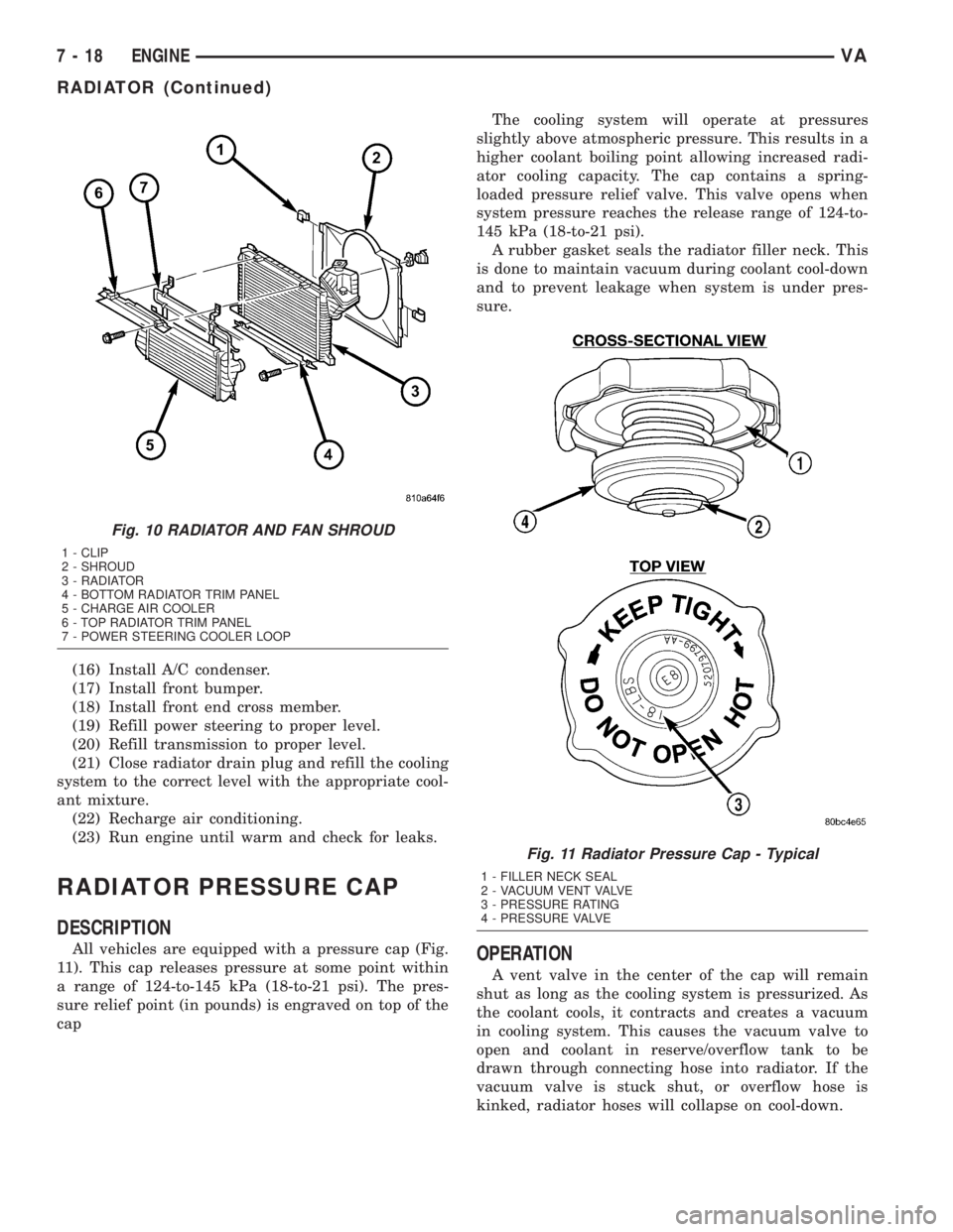
Fig. 10 RADIATOR AND FAN SHROUD
1 - CLIP
2 - SHROUD
3 - RADIATOR
4 - BOTTOM RADIATOR TRIM PANEL
5 - CHARGE AIR COOLER
6 - TOP RADIATOR TRIM PANEL
7 - POWER STEERING COOLER LOOP
Fig. 11 Radiator Pressure Cap - Typical
1 - FILLER NECK SEAL
2 - VACUUM VENT VALVE
3 - PRESSURE RATING
4 - PRESSURE VALVE
7 - 18 ENGINEVA
RADIATOR (Continued)
Page 121 of 1232
ELECTRONIC CONTROL MODULES
TABLE OF CONTENTS
page page
CENTRAL TIMER MODULE
DESCRIPTION..........................1
OPERATION............................2
DIAGNOSIS AND TESTING - CENTRAL TIMER
MODULE.............................2
REMOVAL.............................2
INSTALLATION..........................2
CONTROLLER ANTILOCK BRAKE
DESCRIPTION..........................3
REMOVAL.............................3INSTALLATION..........................3
ENGINE CONTROL MODULE
DESCRIPTION..........................3
REMOVAL.............................4
INSTALLATION..........................4
TRANSMISSION CONTROL MODULE
DESCRIPTION..........................5
OPERATION............................5
STANDARD PROCEDURE - TCM ADAPTATION . 8
CENTRAL TIMER MODULE
DESCRIPTION
The central timer module (CTM) is located beneath
the driver seat. The CTM uses information carried on
the programmable communications interface (PCI)
data bus network along with many hard wired inputs
to monitor many sensor and switch inputs. In
response to those inputs, the circuitry and program-
ming of the CTM allow it to supply the vehicle occu-
pants with audible and visual information, and to
control and integrate many functions and features of
the vehicle through both hard wired outputs and the
transmission of message outputs to other modules in
the vehicle over the PCI data bus.
The features that the CTM supports or controls
include the following:
²Central Locking- The CTM on vehicles
equipped with the optional Vehicle Theft Security
System (VTSS) includes a central locking/unlocking
feature.
²Enhanced Accident Response- The CTM pro-
vides an optional enhanced accident response fea-
ture. This is a programmable feature.
²Panic Mode- The CTM provides support for
the optional RKE system panic mode including horn,
headlamp, and park lamp flash features.
²Power Lock Control- The CTM provides the
optional power lock system features, including sup-
port for the automatic door lock and door lock inhibit
modes.²Programmable Features- The CTM provides
support for certain programmable features.
²Remote Keyless Entry- The CTM provides
the optional Remote Keyless Entry (RKE) system fea-
tures, including support for the RKE Lock (with
optional horn and park lamps flash), Unlock (with
park lamps flash, driver-door-only unlock, and
unlock-all-doors), Panic, and illuminated entry
modes, as well as the ability to be programmed to
recognize up to four RKE transmitters. The RKE
horn, driver-door-only unlock, and unlock-all-doors
features are programmable.
²Vehicle Theft Security System- The CTM
provides control of the optional Vehicle Theft Secu-
rity System (VTSS) features, including support for
the central locking/unlocking mode and control of the
Security indicator in the instrument cluster.
Hard wired circuitry connects the CTM to the elec-
trical system of the vehicle. Refer to the appropriate
wiring information.
Many of the features in the vehicle controlled or
supported by the CTM are programmable using the
DRBIIItscan tool. However, if any of the CTM hard-
ware components are damaged or faulty, the entire
CTM unit must be replaced. The hard wired inputs
or outputs of all CTM versions can be diagnosed
using conventional diagnostic tools and methods;
however, for diagnosis of the CTM or the PCI data
bus, the use of a DRBIIItscan tool is required. Refer
to the appropriate diagnostic information.
VAELECTRONIC CONTROL MODULES 8E - 1
Page 125 of 1232
TRANSMISSION CONTROL
MODULE
DESCRIPTION
The transmission control module (TCM) receives,
processes and sends various digital and analog sig-
nals related to the automatic transmission. In addi-
tion, it processes information received from other
vehicle systems, such as engine torque and speed,
accelerator pedal position, wheel speed, kick-down
switch, traction control information, etc.
The TCM is located under the driver's seat and is
connected to other control modules via a CAN bus. It
controls all shift functions to achieve smooth shift
comfort in all driving situations considering:
²Vehicle speed.
²Transmission status.
²Position of selector lever.
²Selected shift range.
²CAN signals.
²Engine Status.Engine speed limits may be reached in all gears
with full throttle or in kick-down operation. In for-
ward driving, the shift range of the forward gears
can be adjusted by the operator by tipping the selec-
tor lever to the left or right (AutoStick). However, the
TCM features a downshift inhibitor to prevent the
engine from overspeeding.
OPERATION
The transmission control module (TCM) deter-
mines the current operating conditions of the vehicle
and controls the shifting process for shift comfort and
driving situations. It receives this operating data
from sensors and broadcast messages from other
modules.
The TCM uses inputs from several sensors that are
directly hardwired to the controller and it uses sev-
eral indirect inputs that are used to control shifts.
This information is used to actuate the proper sole-
noids in the valve body to achieve the desired gear.
The shift lever assembly (SLA) has several items
that are monitored by the TCM to calculate shift
lever position. The reverse light switch, an integral
part of the SLA, controls the reverse light relay con-
trol circuit. The Brake/Transmission Shift Interlock
(BTSI) solenoid and the park lockout solenoid (also
part of the SLA) are controlled by the TCM.
The ECM and ABS broadcast messages over the
controller area network (CAN C) bus for use by the
TCM. The TCM uses this information, with other
inputs, to determine the transmission operating con-
ditions.
The TCM:
²determines the momentary operating conditions
of the vehicle.
²controls all shift processes.
²considers shift comfort and the driving situation.
The TCM controls the solenoid valves for modulat-
ing shift pressures and gear changes. Relative to the
torque being transmitted, the required pressures are
calculated from load conditions, engine rpm, vehicle
speed, and ATF temperature.
The following functions are contained in the TCM:
²Shift Program
²Downshift Safety
²Torque Converter Lock-Up Clutch.
²Adaptation.
This transmission does not have a TCM relay.
Power is supplied to the SLA and the TCM directly
from the ignition.
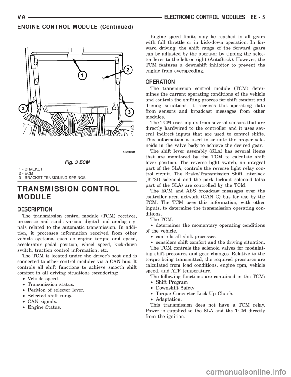
Fig. 3 ECM
1 - BRACKET
2 - ECM
3 - BRACKET TENSIONING SPRINGS
VAELECTRONIC CONTROL MODULES 8E - 5
ENGINE CONTROL MODULE (Continued)
Page 126 of 1232
The TCM continuously checks for electrical prob-
lems, mechanical problems, and some hydraulic prob-
lems. When a problem is sensed, the TCM stores a
diagnostic trouble code (DTC). Some of these codes
cause the transmission to go into9Limp-In9or
9default9mode. Some DTCs cause permanent
Limp-In and others cause temporary Limp-In. The
NAG1 defaults in the current gear position if a DTC
is detected, then after a key cycle the transmission
will go into Limp-in, which is mechanical 2nd gear.
Some DTCs may allow the transmission to resume
normal operation (recover) if the detected problem
goes away. A permanent Limp-In DTC will recover
when the key is cycled, but if the same DTC is
detected for three key cycles the system will not
recover and the DTC must be cleared from the TCM
with the DRBIIItscan tool.
TCM SIGNALS
The TCM registers one part of the input signals by
direct inputs, the other part by CAN C bus. In addi-
tion to the direct control of the actuators, the TCM
sends various output signals by CAN C bus to other
control modules.
Selector Lever Position
The TCM monitors the SLA for all shift lever posi-
tions via the CAN bus.
ATF Temperature Sensor
The ATF temperature sensor is a positive temper-
ature co-efficient (PTC) thermistor. It measures the
temperature of the transmission fluid and is a direct
input signal for the TCM. The temperature of the
ATF has an influence on the shifttime and resulting
shift quality. As the temperature rises, resistance
rises, and therefore, the probing voltage is decreas-
ing. Because of its registration, the shifting process
can be optimized in all temperature ranges.
The ATF temperature sensor is wired in series
with the park/neutral contact. The temperature sig-
nal is transmitted to the TCM only when the reed
contact of the park/neutral contact is closed because
the TCM only reads ATF temperature while in any
forward gear, or REVERSE. When the transmission
is in PARK or NEUTRAL, the TCM will substitute
the engine temperature for the ATF temperature.
Starter Interlock
The TCM monitors a contact switch wired in series
with the transmission temperature sensor to deter-
mine PARK and NEUTRAL positions. The contact
switch is open in PARK and NEUTRAL. The TCM
senses transmission temperature as high (switch
supply voltage), confirming switch status as open.
The TCM then broadcasts a message over CAN bus
to confirm switch status. The PCM receives thisinformation and allows operation of the starter cir-
cuit.
N2 and N3 Speed Sensors
The N2 and N3 Input Speed Sensors are two Hall-
effect speed sensors that are mounted internally in
the transmission and are used by the TCM to calcu-
late the transmission's input speed. Since the input
speed cannot be measured directly, two of the drive
elements are measured. Two input speed sensors
were required because both drive elements are not
active in all gears.
CAN C Bus Indirect Input Signals
A 2.5-volt bias (operating voltage) is present on the
CAN C bus any time the ignition switch is in the
RUN position. Both the TCM and the ABS apply this
bias. On this vehicle, the CAN C bus is used for mod-
ule data exchange only. The indirect inputs used on
the NAG1 electronic control system are:
²Wheel Speed Sensors.
²Brake Switch.
²Engine RPM.
²Engine Temperature.
²Cruise Control Status.
²Gear Limit Request.
²Throttle Position - 0% at idle, 100% at WOT. If
open, TCM assumes idle (0% throttle opening).
²Odometer Mileage
²Maximum Effective Torque.
²Engine in Limp-In Mode/Mileage Where DTC
Was Set.
BRAKE TRANSMISSION SHIFT INTERLOCK (BTSI)
The BTSI solenoid prevents shifting out of the
PARK position until the ignition key is in the RUN
position and the brake pedal is pressed. The TCM
controls the ground while the ignition switch supplies
power to the BTSI solenoid. The PCM monitors the
brake switch and broadcasts brake switch status
messages over the CAN C bus. If the park brake is
depressed and there is power (Run/Start) to SLA, the
BTSI solenoid deactivates.
SHIFT SCHEDULES
The basic shift schedule includes up and down-
shifts for all five gears. The TCM adapts the shift
program according to driving style, accelerator pedal
position and deviation of vehicle speed. Influencing
factors are:
²Road Conditions.
²Incline, Decline and Altitude.
²Trailer Operation, Loading.
²Engine Coolant Temperature.
²Cruise Control Operation.
²Sporty Driving Style.
8E - 6 ELECTRONIC CONTROL MODULESVA
TRANSMISSION CONTROL MODULE (Continued)
Page 127 of 1232
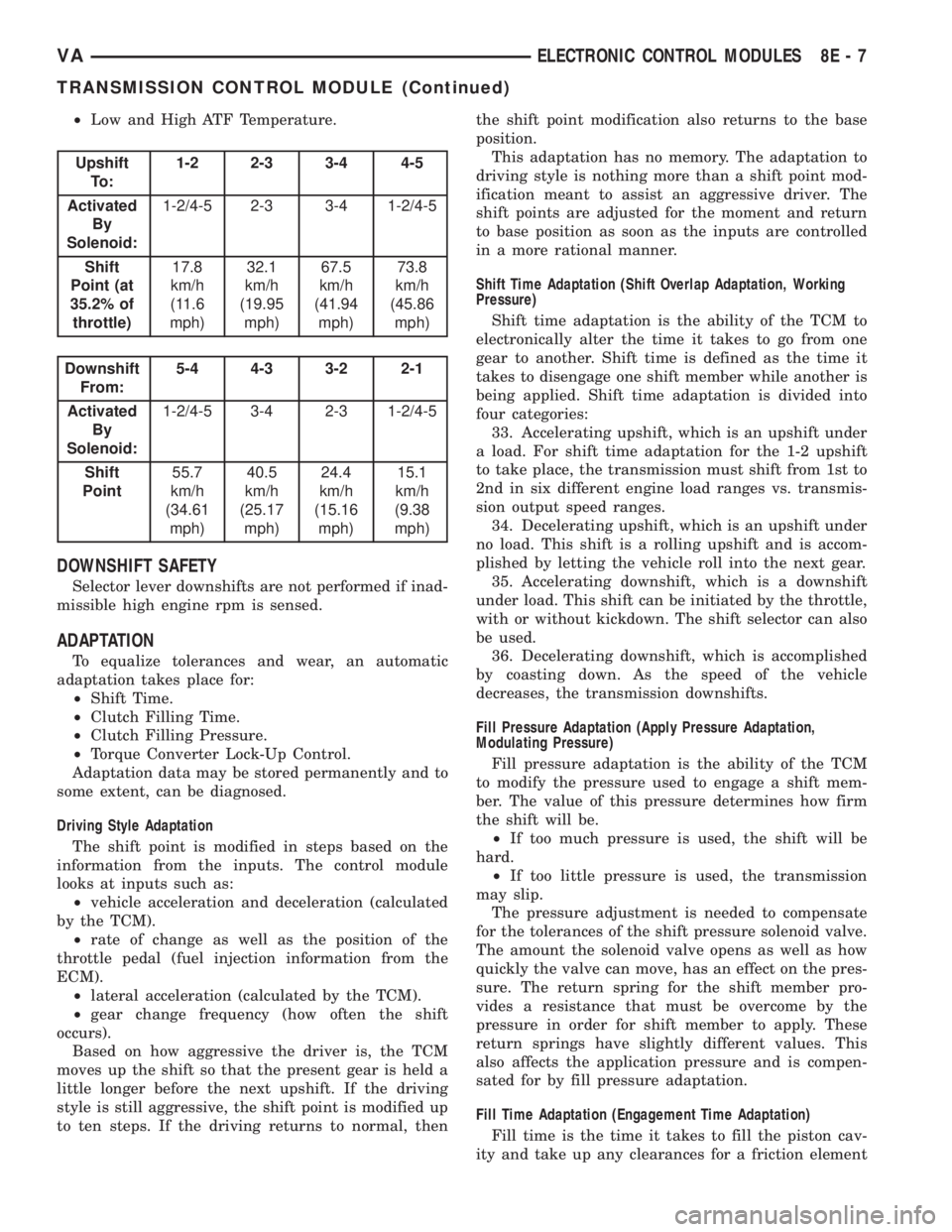
²Low and High ATF Temperature.
Upshift
To :1-2 2-3 3-4 4-5
Activated
By
Solenoid:1-2/4-5 2-3 3-4 1-2/4-5
Shift
Point (at
35.2% of
throttle)17.8
km/h
(11.6
mph)32.1
km/h
(19.95
mph)67.5
km/h
(41.94
mph)73.8
km/h
(45.86
mph)
Downshift
From:5-4 4-3 3-2 2-1
Activated
By
Solenoid:1-2/4-5 3-4 2-3 1-2/4-5
Shift
Point55.7
km/h
(34.61
mph)40.5
km/h
(25.17
mph)24.4
km/h
(15.16
mph)15.1
km/h
(9.38
mph)
DOWNSHIFT SAFETY
Selector lever downshifts are not performed if inad-
missible high engine rpm is sensed.
ADAPTATION
To equalize tolerances and wear, an automatic
adaptation takes place for:
²Shift Time.
²Clutch Filling Time.
²Clutch Filling Pressure.
²Torque Converter Lock-Up Control.
Adaptation data may be stored permanently and to
some extent, can be diagnosed.
Driving Style Adaptation
The shift point is modified in steps based on the
information from the inputs. The control module
looks at inputs such as:
²vehicle acceleration and deceleration (calculated
by the TCM).
²rate of change as well as the position of the
throttle pedal (fuel injection information from the
ECM).
²lateral acceleration (calculated by the TCM).
²gear change frequency (how often the shift
occurs).
Based on how aggressive the driver is, the TCM
moves up the shift so that the present gear is held a
little longer before the next upshift. If the driving
style is still aggressive, the shift point is modified up
to ten steps. If the driving returns to normal, thenthe shift point modification also returns to the base
position.
This adaptation has no memory. The adaptation to
driving style is nothing more than a shift point mod-
ification meant to assist an aggressive driver. The
shift points are adjusted for the moment and return
to base position as soon as the inputs are controlled
in a more rational manner.
Shift Time Adaptation (Shift Overlap Adaptation, Working
Pressure)
Shift time adaptation is the ability of the TCM to
electronically alter the time it takes to go from one
gear to another. Shift time is defined as the time it
takes to disengage one shift member while another is
being applied. Shift time adaptation is divided into
four categories:
33. Accelerating upshift, which is an upshift under
a load. For shift time adaptation for the 1-2 upshift
to take place, the transmission must shift from 1st to
2nd in six different engine load ranges vs. transmis-
sion output speed ranges.
34. Decelerating upshift, which is an upshift under
no load. This shift is a rolling upshift and is accom-
plished by letting the vehicle roll into the next gear.
35. Accelerating downshift, which is a downshift
under load. This shift can be initiated by the throttle,
with or without kickdown. The shift selector can also
be used.
36. Decelerating downshift, which is accomplished
by coasting down. As the speed of the vehicle
decreases, the transmission downshifts.
Fill Pressure Adaptation (Apply Pressure Adaptation,
Modulating Pressure)
Fill pressure adaptation is the ability of the TCM
to modify the pressure used to engage a shift mem-
ber. The value of this pressure determines how firm
the shift will be.
²If too much pressure is used, the shift will be
hard.
²If too little pressure is used, the transmission
may slip.
The pressure adjustment is needed to compensate
for the tolerances of the shift pressure solenoid valve.
The amount the solenoid valve opens as well as how
quickly the valve can move, has an effect on the pres-
sure. The return spring for the shift member pro-
vides a resistance that must be overcome by the
pressure in order for shift member to apply. These
return springs have slightly different values. This
also affects the application pressure and is compen-
sated for by fill pressure adaptation.
Fill Time Adaptation (Engagement Time Adaptation)
Fill time is the time it takes to fill the piston cav-
ity and take up any clearances for a friction element
VAELECTRONIC CONTROL MODULES 8E - 7
TRANSMISSION CONTROL MODULE (Continued)
Page 128 of 1232
(clutch or brake). Fill time adaptation is the ability of
the TCM to modify the time it takes to fill the shift
member by applying a preload pressure.
CONTROLLER MODES OF OPERATION
Permanent Limp-In Mode
When the TCM determines there is a non-recover-
able condition present that does not allow proper
transmission operation, it places the transmission in
permanent Limp-In Mode. When the condition occurs
the TCM turns off all solenoids as well as the sole-
noid supply output circuit. If this occurs while the
vehicle is moving, the transmission remains in the
current gear position until the ignition is turned off
or the shifter is placed in the9P9position. When the
shifter has been placed in9P,9the transmission only
allows 2nd gear operation. If this occurs while the
vehicle is not moving, the transmission only allows
operation in 2nd gear.
Temporary Limp-In Mode
This mode is the same as the permanent Limp-In
Mode except if the condition is no longer present, the
system resumes normal operation.
Under Voltage Limp-In Mode
When the TCM detects that system voltage has
dropped below 8.5 volts, it disables voltage-depen-
dant diagnostics and places the transmission in the
temporary Limp-In Mode. When the TCM senses
that the voltage has risen above 9.0 volts, normal
transmission operation is resumed.
Hardware Error Mode
When the TCM detects a major internal error, the
transmission is placed in the permanent Limp-In
Mode and ceases all communication over the CAN
bus. When the TCM has entered this mode normal
transmission operation does not resume until all
DTCs are cleared from the TCM.
Loss of Drive
If the TCM detects a situation that has resulted or
may result in a catastrophic engine or transmission
problem, the transmission is placed in the neutral
position. Improper Ratio, Input Sensor Overspeed or
Engine Overspeed DTCs cause the loss of drive.
Controlled Limp-in Mode
When a failure does not require the TCM to shut
down the solenoid supply, but the failure is severe
enough that the TCM places the transmission into a
predefined gear, there are several shift performanceconcerns. For instance, if the transmission is slip-
ping, the controller tries to place the transmission
into 3rd gear and maintain 3rd gear for all forward
drive conditions.STANDARD PROCEDURE - TCM ADAPTATION
The adaptation procedure requires the use of the
DRBIIItscan tool. This program allows the elec-
tronic transmission system to re-calibrate itself. This
will provide the proper baseline transmission opera-
tion. The adaptation procedure should be performed
if any of the following procedures are performed:
²Transmission Assembly Replacement
²Transmission Control Module Replacement
²Clutch Plate and/or Seal Replacement
²Electrohydraulic Unit Replacement or Recondi-
tion
(1) With the DRBIIIt, reset the Transmission
adaptives. Resetting the adaptives will set the adap-
tives to factory settings.
NOTE: Perform the Coast Down Adaptations first.
The Transmission Temperature must be greater
than 60ÉC (140ÉF) and less than 70ÉC (158ÉF). Fail-
ure to stay within these temperature ranges will
void the procedure.
(2) Drive the vehicle until the transmission tem-
perature is in the specified range.
(3) Perform 4 to 5 coast downs from 5th to 4th
gear and then 4th to 3rd gear.
NOTE: For Upshift adaptation, the Transmission
temperature must be greater than 60ÉC (140ÉF) and
less than 100ÉC (212ÉF). Failure to stay within these
temperature ranges will void this procedure.
(4) From a stop, moderately accelerate the vehicle
and obtain all forward gear ranges while keeping the
Engine RPM below 1800 RPM. Repeat this procedure
4 to 5 times.
(5) Obtaining 5th gear may be difficult at 1800
RPM. Allow the transmission to shift into 5th gear at
a higher RPM then lower the RPM to 1800 and per-
form manual shifts between 4th and 5th gears using
the shift lever.
(6) The TCM will store the adaptives every 10
minutes. After completion of the adaptation proce-
dure make sure the vehicle stays running for at least
10 minutes.
(7) It is possible to manually store the adaptives
under the 10 minute time frame using the DRBIIIt
Store Adaptives procedure.
8E - 8 ELECTRONIC CONTROL MODULESVA
TRANSMISSION CONTROL MODULE (Continued)
Page 143 of 1232
WARNING: EXPLOSIVE HYDROGEN GAS FORMS IN
AND AROUND THE BATTERY. DO NOT SMOKE, USE
FLAME, OR CREATE SPARKS NEAR THE BATTERY.
PERSONAL INJURY AND/OR VEHICLE DAMAGE MAY
RESULT.
WARNING: THE BATTERY CONTAINS SULFURIC
ACID, WHICH IS POISONOUS AND CAUSTIC. AVOID
CONTACT WITH THE SKIN, EYES, OR CLOTHING.
IN THE EVENT OF CONTACT, FLUSH WITH WATER
AND CALL A PHYSICIAN IMMEDIATELY. KEEP OUT
OF THE REACH OF CHILDREN.
WARNING: IF THE BATTERY IS EQUIPPED WITH
REMOVABLE CELL CAPS, BE CERTAIN THAT EACH
OF THE CELL CAPS IS IN PLACE AND TIGHT BEFORE
THE BATTERY IS RETURNED TO SERVICE. PER-
SONAL INJURY AND/OR VEHICLE DAMAGE MAY
RESULT FROM LOOSE OR MISSING CELL CAPS.
The following operation will require a voltmeter
accurate to 1/10 (0.10) volt. Before performing this
test, be certain that the following procedures are
accomplished:
²The battery is fully-charged and tested. (Refer to
8 - ELECTRICAL/BATTERY SYSTEM/BATTERY -
STANDARD PROCEDURE).
²Fully engage the parking brake.
²Place the automatic transmission gearshift selec-
tor lever in the Park position.
²Verify that all lamps and accessories are turned
off.
²Prevent the engine from starting.
(1) Connect the positive lead of the voltmeter to
the battery negative terminal post. Connect the neg-
ative lead of the voltmeter to the battery negative
cable terminal clamp (Fig. 9). Rotate and hold the
ignition switch in the Start position. Observe the
voltmeter. If voltage is detected, correct the poor con-
nection between the battery negative cable terminal
clamp and the battery negative terminal post.
(2) Connect the positive lead of the voltmeter to
the battery positive terminal post. Connect the nega-
tive lead of the voltmeter to the battery positive cable
terminal clamp (Fig. 10). Rotate and hold the ignition
switch in the Start position. Observe the voltmeter. If
voltage is detected, correct the poor connection
between the battery positive cable terminal clamp
and the battery positive terminal post.
(3) Connect the voltmeter to measure between the
battery positive cable terminal clamp and the starter
solenoid B(+) terminal stud (Fig. 11). Rotate and hold
the ignition switch in the Start position. Observe the
voltmeter. If the reading is above 0.2 volt, clean and
tighten the battery positive cable eyelet terminal con-nection at the starter solenoid B(+) terminal stud.
Repeat the test. If the reading is still above 0.2 volt,
replace the faulty battery positive cable.
(4) Connect the voltmeter to measure between the
battery negative cable terminal clamp and a good
clean ground on the engine block (Fig. 12). Rotate
and hold the ignition switch in the Start position.
Observe the voltmeter. If the reading is above 0.2
volt, clean and tighten the battery negative cable
eyelet terminal connection to the engine block.
Repeat the test. If the reading is still above 0.2 volt,
replace the faulty battery negative cable.
Fig. 9 Test Battery Negative Connection Resistance
- Typical
1 - VOLTMETER
2 - BATTERY
Fig. 10 Test Battery Positive Connection Resistance
- Typical
1 - VOLTMETER
2 - BATTERY
VABATTERY SYSTEM 8F - 15
BATTERY CABLES (Continued)
Page 152 of 1232
STARTING SYSTEM
TABLE OF CONTENTS
page page
STARTING SYSTEM
DESCRIPTION.........................24
OPERATION...........................24
DIAGNOSIS AND TESTING - STARTING
SYSTEM............................25
SPECIFICATIONS
TORQUE - STARTER - DIESEL...........29
SPECIFICATIONS - STARTER MOTOR -
DIESEL.............................29STARTER MOTOR
DIAGNOSIS AND TESTING - STARTER
MOTOR .............................29
REMOVAL.............................30
INSTALLATION.........................31
STARTER MOTOR RELAY
DESCRIPTION.........................31
REMOVAL.............................31
INSTALLATION.........................32
STARTING SYSTEM
DESCRIPTION
The starting system consists of:
²Starter relay
²Starter motor (including an integral starter sole-
noid)
Other components to be considered as part of start-
ing system are:
²Battery
²Battery cables
²Ignition switch and key lock cylinder
²Park/neutral position switch (automatic trans-
mission)
²Wire harnesses and connections.
The Battery, Starting, and Charging systems oper-
ate in conjunction with one another, and must be
tested as a complete system. For correct operation of
starting/charging systems, all components used in
these 3 systems must perform within specifications.
When attempting to diagnose any of these systems, it
is important that you keep their interdependency in
mind.
The diagnostic procedures used in each of these
groups include the most basic conventional diagnostic
methods, to the more sophisticated On-Board Diag-
nostics (OBD) built into the Engine Control Module
(ECM). Use of an induction-type milliampere amme-
ter, volt/ohmmeter, battery charger, carbon pile rheo-
stat (load tester), and 12-volt test lamp may be
required.
Certain starting system components are monitored
by the ECM and may produce a Diagnostic Trouble
Code (DTC).
OPERATION
The starting system components form two separate
circuits. A high-amperage feed circuit that feeds thestarter motor high-amperage, and a low-amperage
control circuit that operates on less than 20 amperes.
The high-amperage feed circuit components include
the battery, the battery cables, the contact disc por-
tion of the starter solenoid, and the starter motor
itself. The low-amperage control circuit components
include the ignition switch, the park/neutral position
switch (automatic transmission), the starter relay,
the electromagnetic windings of the starter solenoid,
and the connecting wire harness components.
If the vehicle is equipped with an automatic trans-
mission, battery voltage is supplied through the low-
amperage control circuit to the coil battery terminal
of the starter relay when the ignition switch is
turned to the momentary Start position. The park/
neutral position switch is installed in series between
the starter relay coil ground terminal and ground.
This normally open switch prevents the starter relay
from being energized and the starter motor from
operating unless the automatic transmission gear
selector is in the Neutral or Park positions.
When the starter relay coil is energized, the nor-
mally open relay contacts close. The relay contacts
connect the relay common feed terminal to the relay
normally open terminal. The closed relay contacts
energize the starter solenoid coil windings.
The energized solenoid pull-in coil pulls in the sole-
noid plunger. The solenoid plunger pulls the shift
lever in the starter motor. This engages the starter
overrunning clutch and pinion gear with the starter
ring gear on the manual transmission flywheel or on
the automatic transmission torque converter or
torque converter drive plate.
As the solenoid plunger reaches the end of its
travel, the solenoid contact disc completes the high-
amperage starter feed circuit and energizes the sole-
noid plunger hold-in coil. Current now flows between
the solenoid battery terminal and the starter motor,
energizing the starter.
8F - 24 STARTING SYSTEMVA
Page 154 of 1232
Starting System Diagnosis
CONDITION POSSIBLE CAUSE CORRECTION
STARTER DOES NOT
DISENGAGE.1. Starter motor
improperly installed.1. Refer to Starter Motor Removal and Installation.
Tighten starter mounting hardware to correct torque
specifications.
2. Starter relay faulty. 2. Refer to Starter Relay Diagnosis and Testing. Replace
starter relay if required.
3. Ignition switch faulty. 3. Refer to Ignition Switch and Key Lock Cylinder.
Replace ignition switch if required.
4. Starter motor faulty. 4. If all other starting system components and circuits test
OK, replace starter motor.
INSPECTION
For complete starter wiring circuit diagrams, refer
to 8, Wiring Diagrams. Before removing any unit
from starting system for repair or diagnosis, perform
the following inspections:
WARNING: ON VEHICLES EQUIPPED WITH AIR-
BAGS, REFER TO 8, PASSIVE RESTRAINT SYS-
TEMS, BEFORE ATTEMPTING ANY STEERING
WHEEL, STEERING COLUMN, OR INSTRUMENT
PANEL COMPONENT DIAGNOSIS OR SERVICE.
FAILURE TO TAKE THE PROPER PRECAUTIONS
COULD RESULT IN ACCIDENTAL AIRBAG DEPLOY-
MENT AND POSSIBLE PERSONAL INJURY.
²Battery- Visually inspect battery for indica-
tions of physical damage and loose or corroded cable
connections. Determine state-of-charge and cranking
capacity of battery. Charge or replace battery if
required. Refer toBatteryin 8, Battery.
²Ignition Switch- Visually inspect ignition
switch for indications of physical damage and loose
or corroded wire harness connections. Refer toIgni-
tion Switch and Key Lock Cylinder.
²Park/Neutral Position Switch- Visually
inspect park/neutral position switch for indications of
physical damage and loose or corroded wire harness
connections. Refer toPark/Neutral Position
Switchin 21, Transmission.
²Starter Relay- Visually inspect starter relay
for indications of physical damage and loose or cor-
roded wire harness connections.
²Starter Motor- Visually inspect starter motor
for indications of physical damage and loose or cor-
roded wire harness connections.
²Starter Solenoid- Visually inspect starter sole-
noid for indications of physical damage and loose or
corroded wire harness connections.
²Wiring- Visually inspect wire harnesses for
damage or corrosion. Repair or replace any faulty
wiring, as required. Refer to 8, Wiring Diagrams.
TESTING
COLD CRANKING TEST
For complete starter wiring circuit diagrams, refer
to 8, Wiring Diagrams. The battery must be fully-
charged and load-tested before proceeding. Refer to
Batteryin 8, Battery.
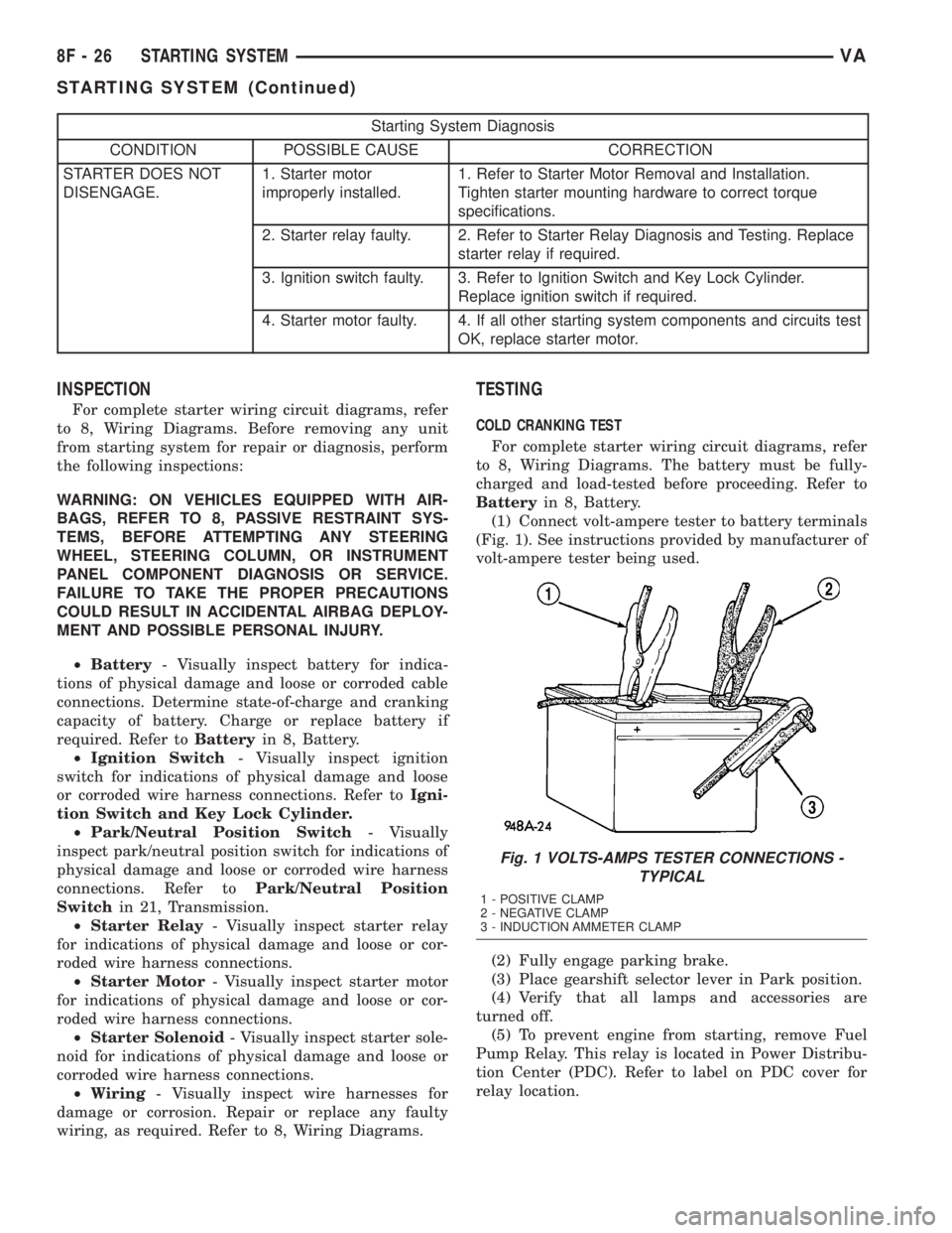
(1) Connect volt-ampere tester to battery terminals
(Fig. 1). See instructions provided by manufacturer of
volt-ampere tester being used.
(2) Fully engage parking brake.
(3) Place gearshift selector lever in Park position.
(4) Verify that all lamps and accessories are
turned off.
(5) To prevent engine from starting, remove Fuel
Pump Relay. This relay is located in Power Distribu-
tion Center (PDC). Refer to label on PDC cover for
relay location.
Fig. 1 VOLTS-AMPS TESTER CONNECTIONS -
TYPICAL
1 - POSITIVE CLAMP
2 - NEGATIVE CLAMP
3 - INDUCTION AMMETER CLAMP
8F - 26 STARTING SYSTEMVA
STARTING SYSTEM (Continued)