wheel bolts MERCEDES-BENZ SPRINTER 2005 Service Owner's Guide
[x] Cancel search | Manufacturer: MERCEDES-BENZ, Model Year: 2005, Model line: SPRINTER, Model: MERCEDES-BENZ SPRINTER 2005Pages: 1232, PDF Size: 39.23 MB
Page 868 of 1232
GEAR
TABLE OF CONTENTS
page page
GEAR
DESCRIPTION..........................8
REMOVAL.............................8INSTALLATION..........................8
SPECIFICATIONS - TORQUE CHART.........9
GEAR
DESCRIPTION
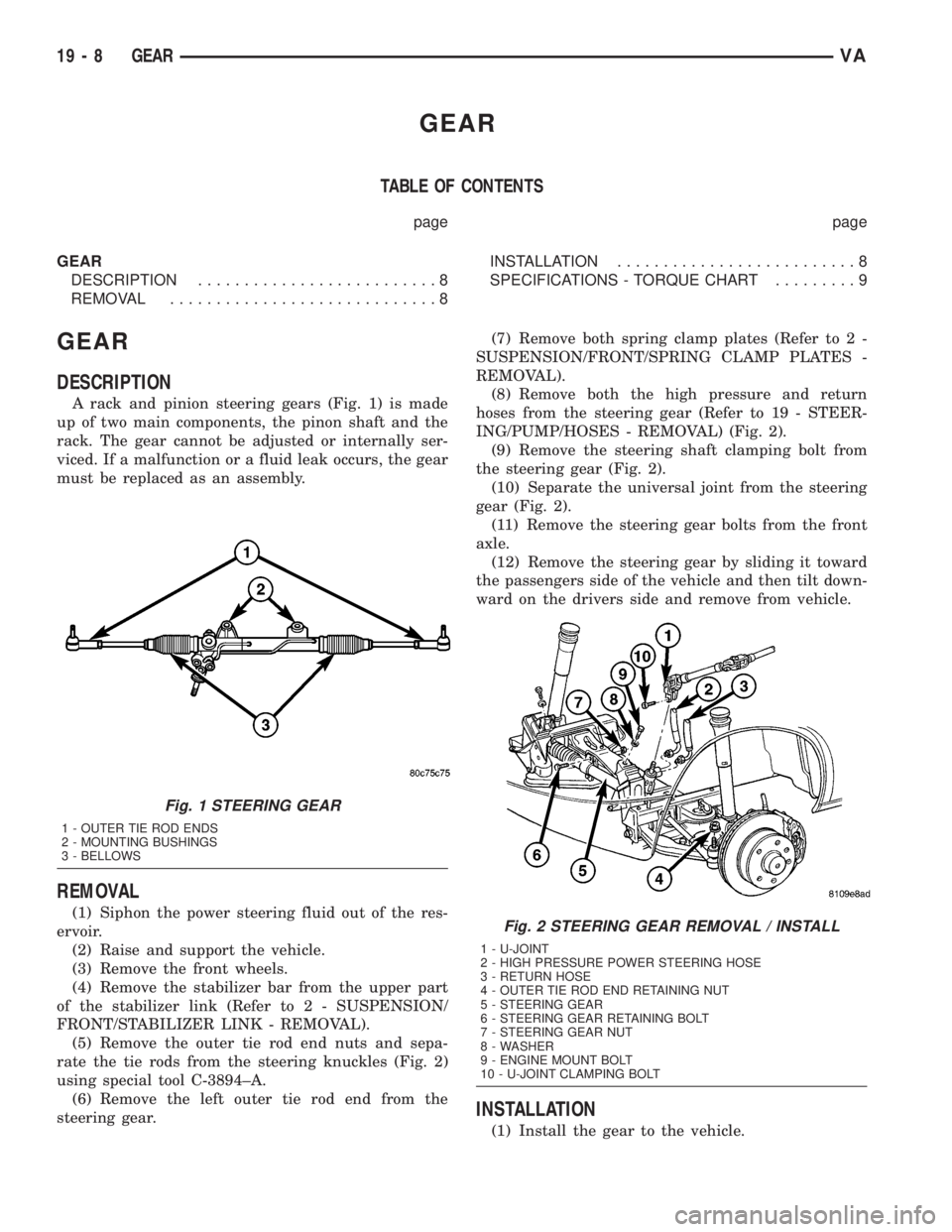
A rack and pinion steering gears (Fig. 1) is made
up of two main components, the pinon shaft and the
rack. The gear cannot be adjusted or internally ser-
viced. If a malfunction or a fluid leak occurs, the gear
must be replaced as an assembly.
REMOVAL
(1) Siphon the power steering fluid out of the res-
ervoir.
(2) Raise and support the vehicle.
(3) Remove the front wheels.
(4) Remove the stabilizer bar from the upper part
of the stabilizer link (Refer to 2 - SUSPENSION/
FRONT/STABILIZER LINK - REMOVAL).
(5) Remove the outer tie rod end nuts and sepa-
rate the tie rods from the steering knuckles (Fig. 2)
using special tool C-3894±A.
(6) Remove the left outer tie rod end from the
steering gear.(7) Remove both spring clamp plates (Refer to 2 -
SUSPENSION/FRONT/SPRING CLAMP PLATES -
REMOVAL).
(8) Remove both the high pressure and return
hoses from the steering gear (Refer to 19 - STEER-
ING/PUMP/HOSES - REMOVAL) (Fig. 2).
(9) Remove the steering shaft clamping bolt from
the steering gear (Fig. 2).
(10) Separate the universal joint from the steering
gear (Fig. 2).
(11) Remove the steering gear bolts from the front
axle.
(12) Remove the steering gear by sliding it toward
the passengers side of the vehicle and then tilt down-
ward on the drivers side and remove from vehicle.
INSTALLATION
(1) Install the gear to the vehicle.
Fig. 1 STEERING GEAR
1 - OUTER TIE ROD ENDS
2 - MOUNTING BUSHINGS
3 - BELLOWS
Fig. 2 STEERING GEAR REMOVAL / INSTALL
1 - U-JOINT
2 - HIGH PRESSURE POWER STEERING HOSE
3 - RETURN HOSE
4 - OUTER TIE ROD END RETAINING NUT
5 - STEERING GEAR
6 - STEERING GEAR RETAINING BOLT
7 - STEERING GEAR NUT
8 - WASHER
9 - ENGINE MOUNT BOLT
10 - U-JOINT CLAMPING BOLT
19 - 8 GEARVA
Page 869 of 1232
NOTE: Steering gear must be torqued in a three
step procedure below.
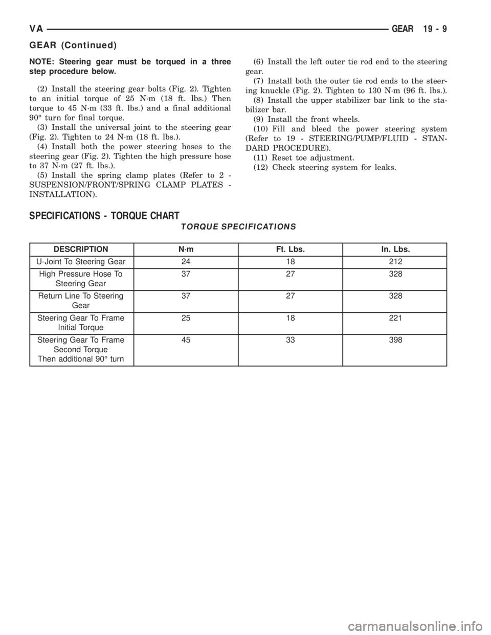
(2) Install the steering gear bolts (Fig. 2). Tighten
to an initial torque of 25 N´m (18 ft. lbs.) Then
torque to 45 N´m (33 ft. lbs.) and a final additional
90É turn for final torque.
(3) Install the universal joint to the steering gear
(Fig. 2). Tighten to 24 N´m (18 ft. lbs.).
(4) Install both the power steering hoses to the
steering gear (Fig. 2). Tighten the high pressure hose
to 37 N´m (27 ft. lbs.).
(5) Install the spring clamp plates (Refer to 2 -
SUSPENSION/FRONT/SPRING CLAMP PLATES -
INSTALLATION).(6) Install the left outer tie rod end to the steering
gear.
(7) Install both the outer tie rod ends to the steer-
ing knuckle (Fig. 2). Tighten to 130 N´m (96 ft. lbs.).
(8) Install the upper stabilizer bar link to the sta-
bilizer bar.
(9) Install the front wheels.
(10) Fill and bleed the power steering system
(Refer to 19 - STEERING/PUMP/FLUID - STAN-
DARD PROCEDURE).
(11) Reset toe adjustment.
(12) Check steering system for leaks.
SPECIFICATIONS - TORQUE CHART
TORQUE SPECIFICATIONS
DESCRIPTION N´m Ft. Lbs. In. Lbs.
U-Joint To Steering Gear 24 18 212
High Pressure Hose To
Steering Gear37 27 328
Return Line To Steering
Gear37 27 328
Steering Gear To Frame
Initial Torque25 18 221
Steering Gear To Frame
Second Torque
Then additional 90É turn45 33 398
VAGEAR 19 - 9
GEAR (Continued)
Page 873 of 1232
Wipe filler cap clean, then check the fluid level.
The dipstick should indicateCOLDwhen the fluid is
at normal temperature.
(1) Turn steering wheel all the way to the left
(2) Fill the pump fluid reservoir to the proper level
and let the fluid settle for at least two (2) minutes.
(3) Raise the front wheels off the ground.
(4)
Slowly turn the steering wheel lock-to-lock 20
times with the engine off while checking the fluid level.
NOTE: For vehicles with long return lines or oil
coolers turn wheel 40 times.
(5) Start the engine. With the engine idling main-
tain the fluid level.
(6) Lower the front wheels and let the engine idle
for two minutes.
(7) Turn the steering wheel in both direction and
verify power assist and quiet operation of the pump.
If the fluid is extremely foamy or milky looking,
allow the vehicle to stand a few minutes and repeat
the procedure.
CAUTION: Do not run a vehicle with foamy fluid for
an extended period. This may cause pump damage.
STANDARD PROCEDURE - FLUSHING POWER
STEERING SYSTEM
Flushing is required when the power steering/hy-
draulic booster system fluid has become contami-
nated. Contaminated fluid in the steering/booster
system can cause seal deterioration and affect steer-
ing gear/booster spool valve operation.
(1) Raise the front end of the vehicle off the
ground until the wheels are free to turn.
(2) Remove the return line from the pump.
NOTE: If vehicle is equipped with a hydraulic
booster remove both return lines from the pump.
(3) Plug the return line port/ports at the pump.
(4) Position the return line/lines into a large con-
tainer to catch the fluid.
(5) While an assistant is filling the pump reservoir
start the engine.
(6) With the engine running at idle turn the wheel
back and forth.
NOTE: Do not contact or hold the wheel against the
steering stops.
(7) Run a quart of fluid through the system then
stop the engine and install the return line/lines.
(8) Fill the system with fluid and perform Steering
Pump Initial Operation, (Refer to 19 - STEERING/
PUMP - STANDARD PROCEDURE).(9) Start the engine and run it for fifteen minutes
then stop the engine.
(10) Remove the return line/lines from the pump
and plug the pump port/ports.
(11) Pour fresh fluid into the reservoir and check
the draining fluid for contamination. If the fluid is
still contaminated, then flush the system again.
(12) Install the return line/lines and perform
Steering Pump Initial Operation, (Refer to 19 -
STEERING/PUMP - STANDARD PROCEDURE).
REMOVAL
(1) Remove the belt from the power steering pump.
(2) Siphon as much power steering fluid as possi-
ble out of the reservoir.
(3) Remove the high pressure power steering hose
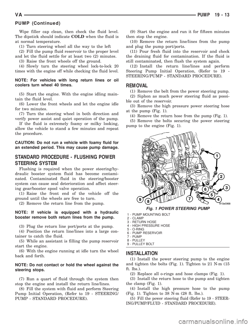
at the pump (Fig. 1).
(4)
Remove the return hose from the pump (Fig. 1).
(5) Remove the bolts securing the power steering
pump to the engine (Fig. 1).
INSTALLATION
(1) Install the power steering pump to the engine
and tighten the bolts (Fig. 1). Tighten to 21 N´m (15
ft. lbs.).
(2) Replace all o-rings and hose clamps (Fig. 1).
(3) Install the return hose to the pump and tighten
the clamp (Fig. 1).
(4) Install the high pressure hose to the pump
(Fig. 1). Tighten to 38 N´m (28 ft. lbs.).
(5)
Fill the power steering fluid (Refer to 19 - STEER-
ING/PUMP/FLUID - STANDARD PROCEDURE).
Fig. 1 POWER STEERING PUMP
1 - PUMP MOUNTING BOLT
2 - CLAMP
3 - RETURN HOSE
4 - HIGH PRESSURE HOSE
5 - O-RING
6 - PUMP RESERVOIR
7 - PUMP
8 - PULLEY
9 - PULLEY BOLT
VAPUMP 19 - 13
PUMP (Continued)
Page 874 of 1232
SPECIFICATIONS - TORQUE CHART
TORQUE SPECIFICATIONS
DESCRIPTION N´m Ft. Lbs. In. Lbs.
Power Steering Pump To
Timing Case Cover/
Support21 15 185
High Pressure Flexible
Hose To Power Steering
Pump38 28 336
Power Steering Pulley To
Pump30 22 265
FLUID
STANDARD PROCEDURE
POWER STEERING PUMP FILL AND BLEED
PROCEDURE
(1) Remove the cap from the fluid reservoir.
Check cap seal for damage and replace if
needed.
(2) Fill the power steering pump with Mopar
ATF+4 Automatic Transmission fluid or equivalent.
Do not fill fluid beyond the MAX mark.
(3) Raise the vehicles front wheels off the ground.
(4) With the engine off turn the steering wheel
from right to left.Perform this step until all the
bubble formations can no longer be seen in the
power steering reservoir.
(5) Start the engine and turn the steering wheel
with the engine at idle speed then shut the engine off
and check for correct oil level and no bubble in the
system.
(6) Reinstall power steering cap tightly.
(7) Test the system for leaks and proper operation.
FLUID COOLER TUBE
REMOVAL
(1) Siphon as much power steering fluid as possi-
ble out of the reservoir.
(2) Remove the grille (Refer to 23 - BODY/EXTE-
RIOR/GRILLE - REMOVAL).
(3) Remove the left headlight assembly.
(4) Disconnect the return lines from the cooler
tube.
(5) Remove the radiator clips (2).
(6) Remove the heat shield bolt for the turbo at
the core support.
(7) Remove the right headlight assembly.(8) Remove the core support bolts (4) and discon-
nect the hood latch cable.
(9) Remove the fan bracket bolts (4) to the radiator
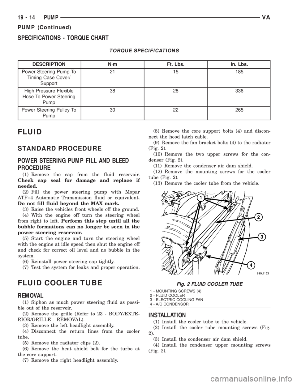
(Fig. 2).
(10) Remove the two upper screws for the con-
denser (Fig. 2).
(11) Remove the condenser air dam shield.
(12) Remove the mounting screws for the cooler
tube (Fig. 2).
(13) Remove the cooler tube from the vehicle.
INSTALLATION
(1) Install the cooler tube to the vehicle.
(2) Install the cooler tube mounting screws (Fig.
2).
(3) Install the condenser air dam shield.
(4) Install the condenser upper mounting screws
(Fig. 2).
Fig. 2 FLUID COOLER TUBE
1 - MOUNTING SCREWS (4)
2 - FLUID COOLER
3 - ELECTRIC COOLING FAN
4 - A/C CONDENSOR
19 - 14 PUMPVA
PUMP (Continued)
Page 981 of 1232

(14) Remove the transmission oil filter and o-ring
from the electrohydraulic control unit.
(15) Clean the inside of the oil pan of any debris.
Inspect the oil pan gasket and replace if necessary.
(16) Install a new oil filter and o-ring into the elec-
trohydraulic control unit.
(17) Install the oil pan and gasket onto the trans-
mission.
(18) Install the oil pan bolts and retainers. Torque
the bolts to 8 N´m (70 in.lbs.).
(19) Lower the vehicle and add 7.0 L (7.4 qts.) of
transmission fluid to the transmission.
(20) Check the oil level (Refer to 21 - TRANSMIS-
SION/AUTOMATIC - NAG1/FLUID AND FILTER -
STANDARD PROCEDURE).
FREEWHEELING CLUTCH
DESCRIPTION
Freewheeling clutches (Fig. 141) are installed in
the front planetary gear set between the sun gear
and the stator shaft, and in the rear planetary gear
set between the sun gear and the intermediate shaft.The freewheel consists of an outer race (4), an
inner race (7), a number of locking elements (3) and
a cage (6) for these locking elements.
OPERATION
The freewheeling clutch (Fig. 142) optimizes indi-
vidual gearshifts. They lock individual elements of a
planetary gear set together or against the transmis-
sion housing in one direction of rotation to allow the
torque to be transmitted.
If the inner race (7) of the freewheeling clutch is
locked and the outer race (4) turns in direction9A9
(1), the locking elements (3) adopt a diagonal position
on account of their special contours, allowing the
freewheel function. The outer race (4) slides over the
locking elements (3) with negligible friction. If the
rotation of the outer race (4) changes to direction9B9
(2), the locking elements (3) stand up and lock the
outer and inner races (4, 7) together.
Fig. 141 Freewheeling Clutch
1 - ROTATION DIRECTION9A9
2 - ROTATION DIRECTION9B9
3 - LOCKING ELEMENTS
4 - OUTER RACE
5 - FRONT OR REAR SUN GEAR
6 - LOCKING ELEMENT CAGE
7 - INNER RACE
Fig. 142 Freewheeling Clutch
1 - ROTATION DIRECTION9A9
2 - ROTATION DIRECTION9B9
3 - LOCKING ELEMENTS
4 - OUTER RACE
5 - FRONT OR REAR SUN GEAR
6 - LOCKING ELEMENT CAGE
7 - INNER RACE
VAAUTOMATIC TRANSMISSION - NAG1 21 - 105
FLUID AND FILTER (Continued)
Page 1034 of 1232

STANDARD PROCEDURE - REPAIRING LEAKS
For proper repairing, a radial tire must be removed
from the wheel. Repairs should only be made if the
defect, or puncture, is in the tread area (Fig. 17). The
tire should be replaced if the puncture is located in
the sidewall.
Deflate tire completely before removing the tire
from the wheel. Use lubrication such as a mild soap
solution when dismounting or mounting tire. Use
tools free of burrs or sharp edges which could dam-
age the tire or wheel rim.
Before mounting tire on wheel, make sure all rust
is removed from the rim bead and repaint if neces-
sary.
Install wheel on vehicle, and tighten to proper
torque specification, (Refer to 22 - TIRES/WHEELS/
WHEELS - SPECIFICATIONS).
CLEANING
Remove the protective coating on the tires before
delivery of a vehicle. This coating may cause deteri-
oration of the tires.
To remove the protective coating, apply warm
water and let it soak for a few minutes. Afterwards,
scrub the coating away with a soft bristle brush.
Steam cleaning may also be used to remove the coat-
ing.
NOTE: DO NOT use gasoline, mineral oil, oil-based
solvent or a wire brush for cleaning.
SPECIFICATIONS
TIRES
SPECIFICATIONS
DESCRIPTION SPECIFICATION
TIRE P225/70R15C
LR D
TIRE LT225/75R16
LR E
TIRE P
SPARE TIRE CARRIER
REMOVAL
(1) Open the back doors.
(2) Loosen the bolts for the spare tire hold down
(Fig. 18).
(3) Push up on the spare tire carrier and push the
hold downs to the side and lower (Fig. 18).
(4) Remove the spare tire.
INSTALLATION
(1) Install the spare tire to the spare tire carrier
(Fig. 18).
(2) Raise the tire and wheel assmbly and hook on
the hold downs (Fig. 18).
(3) Then tighten the hold downs to secure the
spare tire in place and then close the doors.
Fig. 17 TIRE REPAIR AREA
1 - TIRE REPAIR AREA
Fig. 18 SPARE TIRE
1 - HOLD DOWNS
2 - SPARE TIRE
3 - SPARE TIRE CARRIER
22 - 10 TIRES/WHEELSVA
TIRES (Continued)
Page 1090 of 1232

LATCH RELEASE HANDLE
REMOVAL
(1) Remove the screws and remove the release
handle.
(2) Disconnect the cable from handle.
INSTALLATION
(1) Connect latch cable to release handle.
(2) Install handle and install the screws.
PROP ROD
REMOVAL
(1) Open and support hood.
(2) Remove the prop rod retaining clip. (Fig. 1)
(3) Separate the prop and spring from the hood.
(4) Remove nut and position the washer bottle
aside. (Fig. 4)
(5)
Remove stud nut and remove hood prop. (Fig. 5)
INSTALLATION
(1) Install hood prop and install the stud nut.
(2) Position washer bottle back and install the nut
and washer.
(3) Connect spring and prop onto hood and install
the retaining spring.
SAFETY LATCH
REMOVAL
(1) Open hood.
(2) Using a grease pencil or equivalent, mark the
position of the safety latch to aid installation.(3) Remove the bolts and remove the latch. (Fig. 6)
INSTALLATION
(1) Install the latch and install the bolts.
(2) Adjust the latch if necessary. (Refer to 23 -
BODY/HOOD/HOOD - ADJUSTMENTS)
Fig. 4 Washer Reservoir Remove/Install
1 - RIGHT INNER FENDER
2 - WASHER RESERVOIR
3 - NUT & WASHER
4 - ROUTING CLIP
Fig. 5 Washer Reservoir Mounting
1 - RIGHT INNER FENDER
2 - STUD NUT
3 - DASH PANEL
4 - RIGHT FRONT WHEEL HOUSE
5 - GROMMET (2)
6 - HOOD PROP
Fig. 6 SAFETY LATCH
1 - SAFETY LATCH
2 - BOLTS
23 - 52 HOODVA
Page 1094 of 1232

(1) Remove rubber mat from both cup holders.
(2) Unscrew screws (1) and remove cup holder top
section (2). (Fig. 4)
(3) Remove vent hose (1). (Fig. 5)
(4) Unscrew bolts (2) and remove cup holder bot-
tom section (3) from cab floor.INSTALLATION
WARNING: ON VEHICLES EQUIPPED WITH AIR-
BAGS, DISABLE THE AIRBAG SYSTEM BEFORE
ATTEMPTING ANY STEERING WHEEL, STEERING
COLUMN, SEAT BELT TENSIONER, OR INSTRU-
MENT PANEL COMPONENT DIAGNOSIS OR SER-
VICE. DISCONNECT AND ISOLATE THE BATTERY
NEGATIVE (GROUND) CABLE, THEN WAIT TWO
MINUTES FOR THE AIRBAG SYSTEM CAPACITOR
TO DISCHARGE BEFORE PERFORMING FURTHER
DIAGNOSIS OR SERVICE. THIS IS THE ONLY SURE
WAY TO DISABLE THE AIRBAG SYSTEM. FAILURE
TO TAKE THE PROPER PRECAUTIONS COULD
RESULT IN ACCIDENTAL AIRBAG DEPLOYMENT
AND POSSIBLE PERSONAL INJURY.
(1) Install bottom section and install the bolts.
(2) Install vent hose.
(3) Install top section and install the screws.
(4) Install rubber mats.
GLOVE BOX
REMOVAL
(1) Open glove box and remove the screws. (Fig. 6)
(2) Remove glove box and disconnect electrical con-
nector.
INSTALLATION
(1)Connect electrical connector and install glove box.
(2) Install three screws.
Fig. 4 CUP HOLDER
1 - SCREWS
2 - CUPHOLDER
Fig. 5 CUP HOLDER BOTTOM
1 - VENT HOSE
2 - BOLTS (4)
3 - BOTTOM SECTION
Fig. 6 GLOVE BOX
1 - SCREWS (3)
2 - GLOVE BOX DOOR
23 - 56 INSTRUMENT PANELVA
CUP HOLDER (Continued)
Page 1098 of 1232

(22) Remove brake pedal spring. (Fig. 17)
(23) Remove ignition transponder. (Fig. 18)
CAUTION: The position of the steering gear must
not be altered again for the entire duration of the
work procedure.
(24) Turn the steering wheel and lock the steering
wheel in the straight ahead position.
(25) Remove steering column support bolts. (Fig.
19)
(26) Remove the screws and remove instrument
panel. (Fig. 20)
Fig. 17 BRAKE PEDAL SPRING
1 - STEERING COLUMN
2 - SPRING
Fig. 18 IGNITION TRANSPONDER
1 - COLUMN LOCK
2 - IGNITION TRANSPONDER
Fig. 19 STEERING COLUMN BOLTS
1 - BOLTS (2)
2 - STEERING COLUMN
Fig. 20 INSTRUMENT PANEL FASTENERS
1 - UPPER SCREWS (6)
2 - INSTRUMENT PANEL
3 - RIGHT SCREW
4 - CENTER SCREWS (2)
5 - LEFT SCREWS (3)
23 - 60 INSTRUMENT PANELVA
INSTRUMENT PANEL ASSEMBLY (Continued)
Page 1099 of 1232

INSTALLATION
WARNING: ON VEHICLES EQUIPPED WITH AIR-
BAGS, DISABLE THE AIRBAG SYSTEM BEFORE
ATTEMPTING ANY STEERING WHEEL, STEERING
COLUMN, SEAT BELT TENSIONER, OR INSTRU-
MENT PANEL COMPONENT DIAGNOSIS OR SER-
VICE. DISCONNECT AND ISOLATE THE BATTERY
NEGATIVE (GROUND) CABLE, THEN WAIT TWO
MINUTES FOR THE AIRBAG SYSTEM CAPACITOR
TO DISCHARGE BEFORE PERFORMING FURTHER
DIAGNOSIS OR SERVICE. THIS IS THE ONLY SURE
WAY TO DISABLE THE AIRBAG SYSTEM. FAILURE
TO TAKE THE PROPER PRECAUTIONS COULD
RESULT IN ACCIDENTAL AIRBAG DEPLOYMENT
AND POSSIBLE PERSONAL INJURY.
²WHEN REMOVING A DEPLOYED AIRBAG, RUB-
BER GLOVES, EYE PROTECTION, AND A LONG-
SLEEVED SHIRT SHOULD BE WORN. THERE MAY
BE DEPOSITS ON THE AIRBAG UNIT AND OTHER
INTERIOR SURFACES. IN LARGE DOSES, THESE
DEPOSITS MAY CAUSE IRRITATION TO THE SKIN
AND EYES.
²USE EXTREME CARE TO PREVENT ANY FOR-
EIGN MATERIAL FROM ENTERING THE PASSEN-
GER AIRBAG, OR BECOMING ENTRAPPED
BETWEEN THE PASSENGER AIRBAG CUSHION
AND THE PASSENGER AIRBAG DOOR. FAILURE TO
OBSERVE THIS WARNING COULD RESULT IN
OCCUPANT INJURIES UPON AIRBAG DEPLOY-
MENT.
²THE PASSENGER AIRBAG DOOR MUST
NEVER BE PAINTED. REPLACEMENT PASSENGER
AIRBAGS ARE SERVICED WITH DOORS IN THE
ORIGINAL COLORS. PAINT MAY CHANGE THE WAY
IN WHICH THE MATERIAL OF THE AIRBAG DOOR
RESPONDS TO AN AIRBAG DEPLOYMENT. FAIL-
URE TO OBSERVE THIS WARNING COULD RESULT
IN OCCUPANT INJURIES UPON AIRBAG DEPLOY-
MENT.
(1) Install the instrument panel.
NOTE: The guides on the bottom of the instrument
panel must engage in the cutouts on the left and
right next to the heater housing. (Fig. 21) (Fig. 22)
(2) Route wire harness through the panel.
(3) Install and tighten 12 instrument panel screws.
(Fig. 20)
CAUTION: The position of the steering gear must
not be altered.
(4) Raise steering column into position and install
the bolts. (Fig. 19)(5) Tighten steering column bolts to 25 N´m (18 ft.
lbs.).
(6) Install ignition transponder onto column lock.
(Fig. 18)
NOTE: The dome on the transponder must engage
into the groove on the ignition switch.
(7) Install brake pedal spring. (Fig. 17)
(8) Install vent hose. (Fig. 16)
(9) Install instrument panel top cover and screws.
(Fig. 15)
(10) Install right outer and inner air nozzles. (Fig.
13)
(11) Install right side cover and screws.
(12) Wrap protective mat around connectors
behind instrument cluster.
Fig. 21 ALIGNMENT CUTOUT - 1
1 - CUTOUT
2 - HEATER HOUSING
Fig. 22 ALIGNMENT CUTOUT - 2
1 - CUTOUT
2 - HEATER HOUSING
VAINSTRUMENT PANEL 23 - 61
INSTRUMENT PANEL ASSEMBLY (Continued)