fuel pump MERCEDES-BENZ SPRINTER 2005 Service Service Manual
[x] Cancel search | Manufacturer: MERCEDES-BENZ, Model Year: 2005, Model line: SPRINTER, Model: MERCEDES-BENZ SPRINTER 2005Pages: 1232, PDF Size: 39.23 MB
Page 848 of 1232
CRANKSHAFT POSITION
SENSOR
DESCRIPTION
The crankshaft position sensor is located opposite
the teeth on the flywheel and uses a non contact
method to record the position of the crankshaft. The
leading edges of each tooth on the flywheel generate
a positive signal in the position sensor, while the
trailing edges generate a negative signal. When the
crankshaft is rotating, an alternating voltage is pro-
duced as a result.
The period of the signal is the time required by the
crankshaft to turn through the gap between two fly-
wheel teeth. The clearance between the crankshaft
position sensor and the teeth of the flywheel is fixed
by the installation.
Two teeth on the flywheel are missing. The result-
ing signal gap is used by the ECM to detect the TDC
position of cylinder number one.
OPERATION
The clearance between the crankshaft position sen-
sor and the flywheel are fixed by the installation
position. Two teeth on the flywheel are missing. The
resulting gap is used by the ECM to detect DTC of
cylinder number one. The crankshaft position is cal-
culated to an accuracy of a fraction of a degree so
that the start and end of injection can occur at
exactly the right moment. The engine speed signal is
also processed by the ECM from the crankshaft sen-
sor. This signal is then transferred to other control
modules over the CAN bus.
If the crankshaft position sensor fails, the signal
that provides reference rotation is missing. Injection
may occur at the wrong time and damage the engine.
In this case, the ECM will stop triggering the injec-
tors, the engine would cut out, the engine warning
light would illuminate and the engine will not
restart.
REMOVAL
(1) Disconnect the negative battery cable.
(2) Unplug the crankshaft wiring harness connec-
tor.
(3) Remove the crankshaft sensor retaining bolt
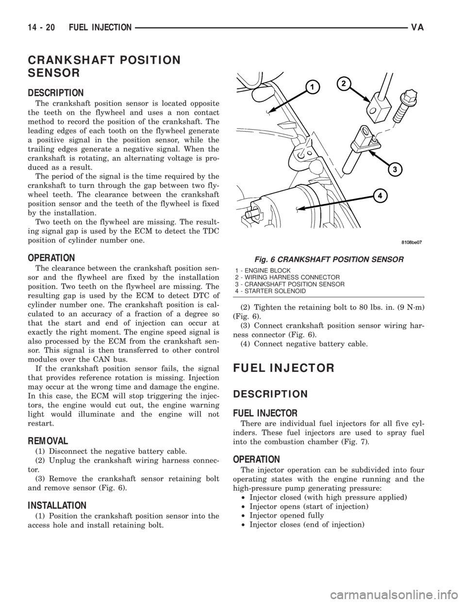
and remove sensor (Fig. 6).
INSTALLATION
(1) Position the crankshaft position sensor into the
access hole and install retaining bolt.(2) Tighten the retaining bolt to 80 lbs. in. (9 N´m)
(Fig. 6).
(3) Connect crankshaft position sensor wiring har-
ness connector (Fig. 6).
(4) Connect negative battery cable.
FUEL INJECTOR
DESCRIPTION
FUEL INJECTOR
There are individual fuel injectors for all five cyl-
inders. These fuel injectors are used to spray fuel
into the combustion chamber (Fig. 7).
OPERATION
The injector operation can be subdivided into four
operating states with the engine running and the
high-pressure pump generating pressure:
²Injector closed (with high pressure applied)
²Injector opens (start of injection)
²Injector opened fully
²Injector closes (end of injection)
Fig. 6 CRANKSHAFT POSITION SENSOR
1 - ENGINE BLOCK
2 - WIRING HARNESS CONNECTOR
3 - CRANKSHAFT POSITION SENSOR
4 - STARTER SOLENOID
14 - 20 FUEL INJECTIONVA
Page 851 of 1232
NOTE: Always replace the seals that seal off the
injectors at the cylinder head to the combustion
chamber and replace the retaining screws.
REMOVAL
WARNING: HIGH-PRESSURE FUEL LINES DELIVER
DIESEL FUEL UNDER EXTREME PRESSURE FROM
THE INJECTION PUMP TO THE FUEL INJECTORS.
THIS MAY BE AS HIGH AS 1600BAR (23,200 PSI).
USE EXTREME CAUTION WHEN INSPECTING FOR
HIGH-PRESSURE FUEL LEAKS. FUEL UNDER THIS
AMOUNT OF PRESSURE CAN PENETRATE SKIN
CAUSING PERSONAL INJURY OR DEATH. INSPECT
FOR HIGH-PRESSURE LEAKS WITH A SHEET OF
CARD BOARD. WEAR SAFETY GOGGLES AND
ADEQUATE PROTECTIVE CLOTHING WHEN SER-
VICING FUEL SYSTEM.
WARNING: NO SPARKS, OPEN FLAMES OR SMOK-
ING. RISK OF POISONING FROM INHALING AND
SWALLOWING FUEL. RISK OF INJURY TO EYES
AND SKIN FROM CONTACT WITH FUEL. POUR
FUELS ONLY INTO SUITABLE AND APPROPRI-
ATELY MARKED CONTAINERS. WEAR PROTECTIVE
CLOTHING.
NOTE: The engine must be lowered in the vehicle to
remove the fourth and fifth cylinders fuel injectors.
(1) Disconnect negative battery cable.
(2) Remove engine cover (Refer to 9 - ENGINE -
REMOVAL).
(3) Raise and suitably support the vehicle.
(4) Remove lower radiator deflector plate.
(5) Drain cooling system (Refer to 7 - COOLING/
ENGINE/COOLANT - STANDARD PROCEDURE).
(6) Remove turbocharger down pipe assembly.
(7) Remove oil dipstick tube retaining bolt and pull
tube from oil pan.
(8) Lower vehicle.
(9) Remove upper radiator hose.
(10) Remove air cleaner box assembly and hoses.
(11) Remove charge air cooler inlet hose.
(12) Remove charge air cooler to turbocharger inlet
adaptor.
(13) Remove turbocharger to right engine mount
bracket.
(14) Disconnect steering coupler at gear box (RHD
Only).
(15) Remove battery (Refer to 8 - ELECTRICAL/
BATTERY SYSTEM/BATTERY - REMOVAL).
(16) Unclip PDC from battery tray and set aside.(17) Remove battery tray (Refer to 8 - ELECTRI-
CAL/BATTERY SYSTEM/TRAY - REMOVAL).
(18) Remove power steering reservoir (Refer to 19 -
STEERING/PUMP/RESERVOIR - REMOVAL).
(19) Remove charger air cooler outlet hose.
(20) Remove intake manifold to left engine mount
bracket.
(21) Evacuate air conditioning system (Refer to 24
- HEATING & AIR CONDITIONING/PLUMBING -
STANDARD PROCEDURE).
(22) Disconnect air conditioning suction / discharge
lines at A/C compressor.
(23) Disconnect pedal position sensor electrical
connector.
(24) Unplug injector electrical connectors.
(25) Remove fuel / water separator to intake man-
ifold retaining bolts.
(26) Support engine with hoist.
(27) Remove engine mount through bolts.
(28) Remove right engine mount sill plate.
NOTE: Counterhold injection lines with wrench
socket at threaded connections of injectors.
(29) Disconnect fuel injector high pressure line.
(30) Remove fuel injector retaining bolt and ten-
sion claw.
(31) Suitably lower engine to gain fuel injector
access and remove injector.
NOTE: If injectors are tight, remove with extraction
claw in place of tensioning claw. If extraction claw
contacts cylinder head cover, remove cylinder head
cover. If necessary, remove injectors with threaded
adaptor and discard injector.
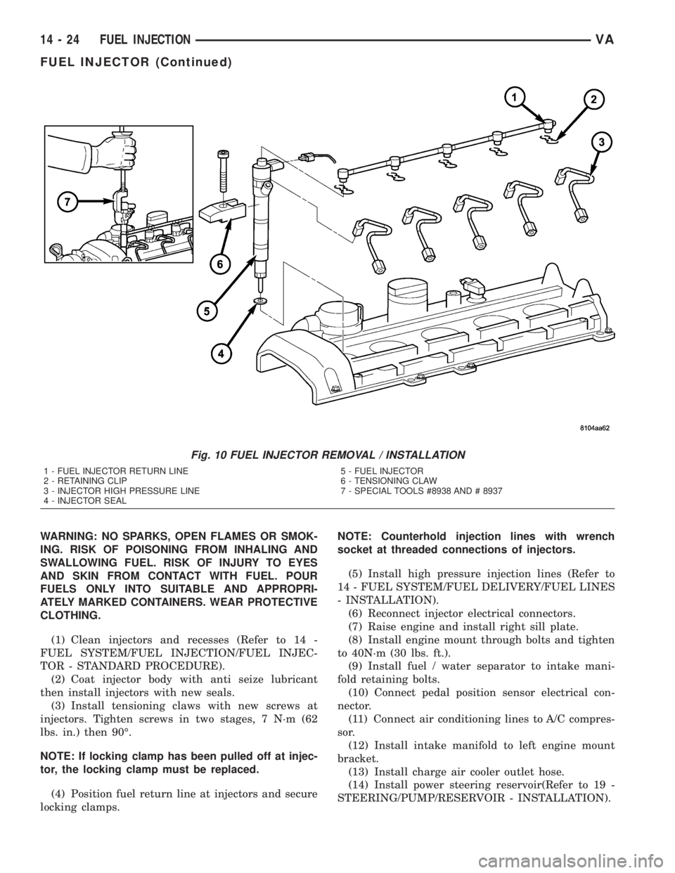
(32) Remove injectors (Fig. 10).
(33) Clean injectors and recesses (Refer to 14 -
FUEL SYSTEM/FUEL INJECTION/FUEL INJEC-
TOR - STANDARD PROCEDURE).
INSTALLATION
WARNING: HIGH-PRESSURE FUEL LINES DELIVER
DIESEL FUEL UNDER EXTREME PRESSURE FROM
THE INJECTION PUMP TO THE FUEL INJECTORS.
THIS MAY BE AS HIGH AS 1600BAR (23,200 PSI).
USE EXTREME CAUTION WHEN INSPECTING FOR
HIGH-PRESSURE FUEL LEAKS. FUEL UNDER THIS
AMOUNT OF PRESSURE CAN PENETRATE SKIN
CAUSING PERSONAL INJURY OR DEATH. INSPECT
FOR HIGH-PRESSURE LEAKS WITH A SHEET OF
CARD BOARD. WEAR SAFETY GOGGLES AND
ADEQUATE PROTECTIVE CLOTHING WHEN SER-
VICING FUEL SYSTEM.
VAFUEL INJECTION 14 - 23
FUEL INJECTOR (Continued)
Page 852 of 1232
WARNING: NO SPARKS, OPEN FLAMES OR SMOK-
ING. RISK OF POISONING FROM INHALING AND
SWALLOWING FUEL. RISK OF INJURY TO EYES
AND SKIN FROM CONTACT WITH FUEL. POUR
FUELS ONLY INTO SUITABLE AND APPROPRI-
ATELY MARKED CONTAINERS. WEAR PROTECTIVE
CLOTHING.
(1) Clean injectors and recesses (Refer to 14 -
FUEL SYSTEM/FUEL INJECTION/FUEL INJEC-
TOR - STANDARD PROCEDURE).
(2) Coat injector body with anti seize lubricant
then install injectors with new seals.
(3) Install tensioning claws with new screws at
injectors. Tighten screws in two stages, 7 N´m (62
lbs. in.) then 90É.
NOTE: If locking clamp has been pulled off at injec-
tor, the locking clamp must be replaced.
(4) Position fuel return line at injectors and secure
locking clamps.NOTE: Counterhold injection lines with wrench
socket at threaded connections of injectors.
(5) Install high pressure injection lines (Refer to
14 - FUEL SYSTEM/FUEL DELIVERY/FUEL LINES
- INSTALLATION).
(6) Reconnect injector electrical connectors.
(7) Raise engine and install right sill plate.
(8) Install engine mount through bolts and tighten
to 40N´m (30 lbs. ft.).
(9) Install fuel / water separator to intake mani-
fold retaining bolts.
(10) Connect pedal position sensor electrical con-
nector.
(11) Connect air conditioning lines to A/C compres-
sor.
(12) Install intake manifold to left engine mount
bracket.
(13) Install charge air cooler outlet hose.
(14) Install power steering reservoir(Refer to 19 -
STEERING/PUMP/RESERVOIR - INSTALLATION).
Fig. 10 FUEL INJECTOR REMOVAL / INSTALLATION
1 - FUEL INJECTOR RETURN LINE
2 - RETAINING CLIP
3 - INJECTOR HIGH PRESSURE LINE
4 - INJECTOR SEAL5 - FUEL INJECTOR
6 - TENSIONING CLAW
7 - SPECIAL TOOLS #8938 AND # 8937
14 - 24 FUEL INJECTIONVA
FUEL INJECTOR (Continued)
Page 853 of 1232
(15) Install battery tray(Refer to 8 - ELECTRI-
CAL/BATTERY SYSTEM/TRAY - INSTALLATION).
(16) Connect PDC to battery tray.
(17) Install battery (Refer to 8 - ELECTRICAL/
BATTERY SYSTEM/BATTERY - INSTALLATION).
(18) Connect steering coupler at gear box (RHD
Only).
(19) Install turbocharger to right engine mount
bracket (Refer to 11 - EXHAUST SYSTEM/TURBO-
CHARGER SYSTEM - INSTALLATION).
(20) Install charge air cooler to turbocharger inlet
adaptor (Refer to 11 - EXHAUST SYSTEM/CHARGE
AIR COOLER AND PLUMBING - INSTALLATION) .
(21) Install charger air cooler inlet hose (Refer to
11 - EXHAUST SYSTEM/CHARGE AIR COOLER
AND PLUMBING - INSTALLATION).
(22) Install air cleaner box assembly and hoses.
(23) Install upper radiator hose.
(24) Raise vehicle.
(25) Install dipstick tube into oil pan and tighten
retaining bolt.
(26) Install turbocharger down pipe assembly.
(27) Close cooling system drain.
(28) Install lower radiator deflector plate.
(29) Lower vehicle.
(30) Connect negative battery cable.
(31) Install engine cover (Refer to 9 - ENGINE -
INSTALLATION)..
(32) Fill cooling system with the correct mixture to
the proper level (Refer to 7 - COOLING/ENGINE/
COOLANT - STANDARD PROCEDURE).
WARNING: USE EXTREME CAUTION WHEN THE
ENGINE IS OPERATING. DO NOT PUT YOUR
HANDS NEAR PULLEYS, BELTS OR FAN. DO NOT
WEAR LOOSE CLOTHING.
(33) Start engine and inspect for leaks.
(34) Recharge air conditioning system.
FUEL PRESSURE SENSOR
DESCRIPTION
DESCRIPTION
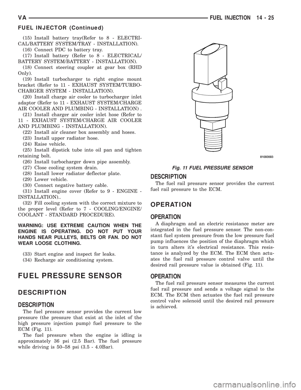
The fuel pressure sensor provides the current low
pressure (the pressure that exist at the inlet of the
high pressure injection pump) fuel pressure to the
ECM (Fig. 11).
The fuel pressure when the engine is idling is
approximately 36 psi (2.5 Bar). The fuel pressure
while driving is 50±58 psi (3.5 - 4.0Bar).
DESCRIPTION
The fuel rail pressure sensor provides the current
fuel rail pressure to the ECM.
OPERATION
OPERATION
A diaphragm and an electric resistance meter are
integrated in the fuel pressure sensor. The non-con-
stant fuel system pressure from the low pressure fuel
pump influences the position of the diaphragm which
in turn alters it's electrical resistance. This resis-
tance is analyzed by the ECM. The ECM then actu-
ates the fuel rail pressure control valve until the
desired rail pressure value is obtained (Fig. 11).
OPERATION
The fuel rail pressure sensor measures the current
fuel rail pressure and sends a voltage signal to the
ECM. The ECM then actuates the fuel rail pressure
control valve solenoid until the desired rail pressure
is achieved.
Fig. 11 FUEL PRESSURE SENSOR
VAFUEL INJECTION 14 - 25
FUEL INJECTOR (Continued)
Page 854 of 1232
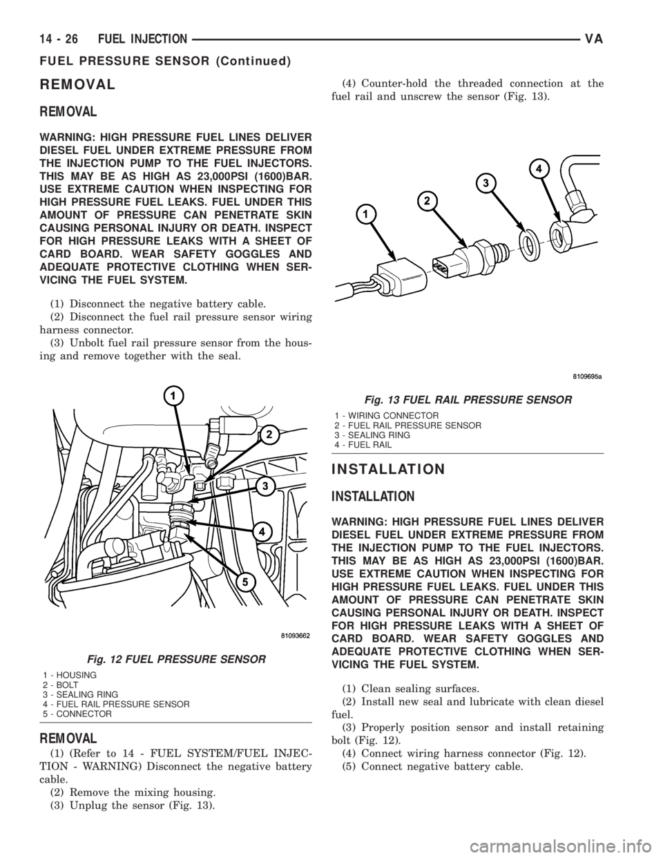
REMOVAL
REMOVAL
WARNING: HIGH PRESSURE FUEL LINES DELIVER
DIESEL FUEL UNDER EXTREME PRESSURE FROM
THE INJECTION PUMP TO THE FUEL INJECTORS.
THIS MAY BE AS HIGH AS 23,000PSI (1600)BAR.
USE EXTREME CAUTION WHEN INSPECTING FOR
HIGH PRESSURE FUEL LEAKS. FUEL UNDER THIS
AMOUNT OF PRESSURE CAN PENETRATE SKIN
CAUSING PERSONAL INJURY OR DEATH. INSPECT
FOR HIGH PRESSURE LEAKS WITH A SHEET OF
CARD BOARD. WEAR SAFETY GOGGLES AND
ADEQUATE PROTECTIVE CLOTHING WHEN SER-
VICING THE FUEL SYSTEM.
(1) Disconnect the negative battery cable.
(2) Disconnect the fuel rail pressure sensor wiring
harness connector.
(3) Unbolt fuel rail pressure sensor from the hous-
ing and remove together with the seal.
REMOVAL
(1) (Refer to 14 - FUEL SYSTEM/FUEL INJEC-
TION - WARNING) Disconnect the negative battery
cable.
(2) Remove the mixing housing.
(3) Unplug the sensor (Fig. 13).(4) Counter-hold the threaded connection at the
fuel rail and unscrew the sensor (Fig. 13).
INSTALLATION
INSTALLATION
WARNING: HIGH PRESSURE FUEL LINES DELIVER
DIESEL FUEL UNDER EXTREME PRESSURE FROM
THE INJECTION PUMP TO THE FUEL INJECTORS.
THIS MAY BE AS HIGH AS 23,000PSI (1600)BAR.
USE EXTREME CAUTION WHEN INSPECTING FOR
HIGH PRESSURE FUEL LEAKS. FUEL UNDER THIS
AMOUNT OF PRESSURE CAN PENETRATE SKIN
CAUSING PERSONAL INJURY OR DEATH. INSPECT
FOR HIGH PRESSURE LEAKS WITH A SHEET OF
CARD BOARD. WEAR SAFETY GOGGLES AND
ADEQUATE PROTECTIVE CLOTHING WHEN SER-
VICING THE FUEL SYSTEM.
(1) Clean sealing surfaces.
(2) Install new seal and lubricate with clean diesel
fuel.
(3) Properly position sensor and install retaining
bolt (Fig. 12).
(4) Connect wiring harness connector (Fig. 12).
(5) Connect negative battery cable.
Fig. 12 FUEL PRESSURE SENSOR
1 - HOUSING
2 - BOLT
3 - SEALING RING
4 - FUEL RAIL PRESSURE SENSOR
5 - CONNECTOR
Fig. 13 FUEL RAIL PRESSURE SENSOR
1 - WIRING CONNECTOR
2 - FUEL RAIL PRESSURE SENSOR
3 - SEALING RING
4 - FUEL RAIL
14 - 26 FUEL INJECTIONVA
FUEL PRESSURE SENSOR (Continued)
Page 856 of 1232
REMOVAL
WARNING: HIGH-PRESSURE FUEL LINES DELIVER
DIESEL FUEL UNDER EXTREME PRESSURE FROM
THE INJECTION PUMP TO THE FUEL INJECTORS.
THIS MAY BE AS HIGH AS 1600BAR (23,200 PSI).
USE EXTREME CAUTION WHEN INSPECTING FOR
HIGH-PRESSURE FUEL LEAKS. FUEL UNDER THIS
AMOUNT OF PRESSURE CAN PENETRATE SKIN
CAUSING PERSONAL INJURY OR DEATH. INSPECT
FOR HIGH-PRESSURE LEAKS WITH A SHEET OF
CARD BOARD. WEAR SAFETY GOGGLES AND
ADEQUATE PROTECTIVE CLOTHING WHEN SER-
VICING FUEL SYSTEM.
WARNING: NO SPARKS, OPEN FLAMES OR SMOK-
ING. RISK OF POISONING FROM INHALING AND
SWALLOWING FUEL. RISK OF INJURY TO EYES
AND SKIN FROM CONTACT WITH FUEL. POUR
FUELS ONLY INTO SUITABLE AND APPROPRI-
ATELY MARKED CONTAINERS. WEAR PROTECTIVE
CLOTHING.
(1) Disconnect negative battery cable.
(2) Remove fuel rail (Refer to 14 - FUEL SYSTEM/
FUEL INJECTION/FUEL INJECTOR - REMOVAL).
(3) Clamp fuel rail securely in vise with protective
jaws.
NOTE: Once removed, the pressure solenoid must
always be replaced.
(4) Remove fuel pressure solenoid retaining screws
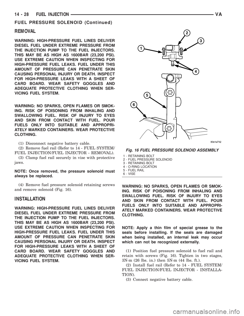
and remove solenoid (Fig. 16).
INSTALLATION
WARNING: HIGH-PRESSURE FUEL LINES DELIVER
DIESEL FUEL UNDER EXTREME PRESSURE FROM
THE INJECTION PUMP TO THE FUEL INJECTORS.
THIS MAY BE AS HIGH AS 1600BAR (23,200 PSI).
USE EXTREME CAUTION WHEN INSPECTING FOR
HIGH-PRESSURE FUEL LEAKS. FUEL UNDER THIS
AMOUNT OF PRESSURE CAN PENETRATE SKIN
CAUSING PERSONAL INJURY OR DEATH. INSPECT
FOR HIGH-PRESSURE LEAKS WITH A SHEET OF
CARD BOARD. WEAR SAFETY GOGGLES AND
ADEQUATE PROTECTIVE CLOTHING WHEN SER-
VICING FUEL SYSTEM.WARNING: NO SPARKS, OPEN FLAMES OR SMOK-
ING. RISK OF POISONING FROM INHALING AND
SWALLOWING FUEL. RISK OF INJURY TO EYES
AND SKIN FROM CONTACT WITH FUEL. POUR
FUELS ONLY INTO SUITABLE AND APPROPRI-
ATELY MARKED CONTAINERS. WEAR PROTECTIVE
CLOTHING.
NOTE: Apply a thin film of special grease to the
seals before installing. If the seals are damaged
when being installed, an internal leak may occur
which can not be recognized externally.
(1) Position fuel pressure solenoid to fuel rail and
retain with screws (Fig. 16). Tighten in two stages,
3N´m (26 lbs. in.) then 5N´m (44 lbs. ft.).
(2) Install fuel rail (Refer to 14 - FUEL SYSTEM/
FUEL INJECTION/FUEL INJECTOR - INSTALLA-
TION).
(3) Connect negative battery cable.
Fig. 16 FUEL PRESSURE SOLENOID ASSEMBLY
1 - RETAINING BOLT
2 - FUEL PRESSURE SOLENOID
3 - RETAINING BOLT
4 - O-RING LOCATION
5 - FUEL RAIL
6 - VISE
14 - 28 FUEL INJECTIONVA
FUEL PRESSURE SOLENOID (Continued)
Page 857 of 1232
WARNING: USE EXTREME CAUTION WHEN ENGINE
IS OPERATING. DO NOT PUT YOUR HANDS NEAR
PULLEYS, BELTS, OR FAN. DO NOT WEAR LOOSE
CLOTHES.
(4) Start engine and inspect for leaks (Refer to 14 -
FUEL SYSTEM - DIAGNOSIS AND TESTING).
FUEL TEMPERATURE SENSOR
DESCRIPTION
The fuel temperature sensor is located in the fuel
return line directly down stream of the fuel rail pres-
sure control valve. The sensor measures the temper-
ature of the fuel in the return pipe between the rail
and the pre-heating valve. The sensor ranges from -
40ÉF (- 40C) to 284ÉF (140ÉC). If the engine is cold,
the actual value sent will read ambient temperature.
The value rises after the engine has been started.
OPERATION
An negative temperature coefficient (NTC) resistor
integrated in the fuel temperature sensor alters it's
electrical resistance in line with the fuel temperature
(the resistance drops as the temperature rises). If
fuel temperature has reached 248ÉF and engine
speed is above 2000 rpm, a pumping element of the
high pressure fuel injection pump is switched off and
engine output is reduced.
REMOVAL
(1) Disconnect the negative battery cable.
(2) Disconnect the sensor wiring harness connector
(Refer to 14 - FUEL SYSTEM/FUEL INJECTION -
WARNING).
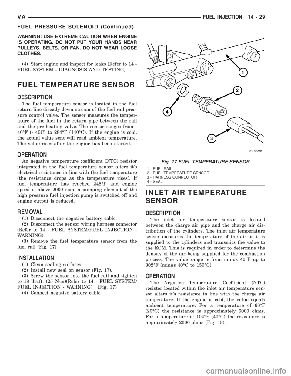
(3) Remove the fuel temperature sensor from the
fuel rail (Fig. 17).
INSTALLATION
(1) Clean sealing surfaces.
(2) Install new seal on sensor (Fig. 17).
(3) Screw the sensor into the fuel rail and tighten
to 18 lbs.ft. (25 N´m)(Refer to 14 - FUEL SYSTEM/
FUEL INJECTION - WARNING) . (Fig. 17)
(4) Connect negative battery cable.
INLET AIR TEMPERATURE
SENSOR
DESCRIPTION
The inlet air temperature sensor is located
between the charge air pipe and the charge air dis-
tribution of the cylinders. The inlet air temperature
sensor measures the temperature of the air as it is
supplied to the cylinders and transmits the value to
the ECM. This is required in order to determine the
density of the air being supplied for the combustion
process. The value range is from minus 40ÉF up to
302ÉF (minus 40ÉC to 150ÉC).
OPERATION
The Negative Temperature Coefficient (NTC)
resister located within the inlet air temperature sen-
sor alters it's resistance in line with the charge air
temperature. If the engine is cold, the value equals
ambient temperature. For a temperature of 68ÉF
(20ÉC) the resistance is approximately 6000 ohms.
For a temperature of 104ÉF (40ÉC) the resistance is
approximately 2600 ohms (Fig. 18).
Fig. 17 FUEL TEMPERATURE SENSOR
1 - FUEL RAIL
2 - FUEL TEMPERATURE SENSOR
3 - HARNESS CONNECTOR
4 - SEAL
VAFUEL INJECTION 14 - 29
FUEL PRESSURE SOLENOID (Continued)
Page 878 of 1232
OUTPUT SHAFT SEAL
REMOVAL............................125
INSTALLATION........................125
PARK LOCK CABLE
REMOVAL............................125
INSTALLATION........................126
PISTONS
DESCRIPTION........................128
OPERATION..........................128
PLANETARY GEARTRAIN
DESCRIPTION........................130
OPERATION..........................130
DISASSEMBLY........................131
ASSEMBLY...........................131
SHIFT MECHANISM
DESCRIPTION........................133
OPERATION..........................133
REMOVAL............................134
INSTALLATION........................135
SOLENOID
DESCRIPTION........................136OPERATION..........................138
TEMPERATURE SENSOR/PARK-NEUTRAL
CONTACT
DESCRIPTION
DESCRIPTION - PARK/NEUTRAL CONTACT . 139
DESCRIPTION - TRANSMISSION
TEMPERATURE SENSOR..............140
OPERATION
OPERATION - PARK/NEUTRAL CONTACT . . 140
OPERATION - TRANSMISSION
TEMPERATURE SENSOR..............141
TORQUE CONVERTER
DESCRIPTION........................141
OPERATION..........................143
REMOVAL............................146
INSTALLATION........................146
TORQUE CONVERTER HUB SEAL
REMOVAL............................147
INSTALLATION........................147
AUTOMATIC TRANSMISSION -
NAG1
DESCRIPTION
The NAG1 automatic transmission (Fig. 1) is an
electronically controlled 5-speed transmission with a
lock-up clutch in the torque converter. The ratios for
the gear stages are obtained by 3 planetary gear sets.
Fifth gear is designed as an overdrive with a high-
speed ratio.
The gears are actuated electronically/hydraulically.
The gears are shifted by means of an appropriate
combination of three multi-disc holding clutches,
three multi-disc driving clutches, and two freewheel-
ing clutches.
Electronic transmission control enables precise
adaptation of pressures to the respective operating
conditions and to the engine output during the shift
phase which results in a significant improvement in
shift quality.
Furthermore, it offers the advantage of a flexible
adaptation to various vehicle and engines.
Basically, the automatic transmission with elec-
tronic control offers the following advantages:
²Reduces fuel consumption.
²Improved shift comfort.
²More favourable step-up through the five gears.
²Increased service life and reliability.
²Lower maintenance costs.
TRANSMISSION IDENTIFICATION
The transmission name, NAG1, means New Auto-
matic Gearbox, generation 1.
The transmission can be generically identified
visually by the presence of a round 13-way connector
located near the front corner of the transmission oil
pan, on the right side. Specific transmission informa-
tion can be found stamped into a pad on the left side
of the transmission, above the oil pan rail.
TRANSMISSION GEAR RATIOS
The gear ratios for the NAG1 automatic transmis-
sion are as follows:
1st Gear.............................3.59:1
2nd Gear............................2.19:1
3rd Gear............................1.41:1
4th Gear............................1.00:1
5th Gear............................0.83:1
Reverse.............................3.16:1
TRANSMISSION HOUSING
The converter housing and transmission are made
from a light alloy. These are bolted together and cen-
tered via the outer multi-disc carrier of multi-disc
holding clutch, B1. A coated intermediate plate pro-
vides the sealing. The oil pump and the outer multi-
disc carrier of the multi-disc holding clutch, B1, are
bolted to the converter housing. The stator shaft is
pressed into it and prevented from rotating by
splines. The electrohydraulic unit is bolted to the
transmission housing from underneath. A sheet
metal steel oil pan forms the closure.
21 - 2 AUTOMATIC TRANSMISSION - NAG1VA
Page 1017 of 1232
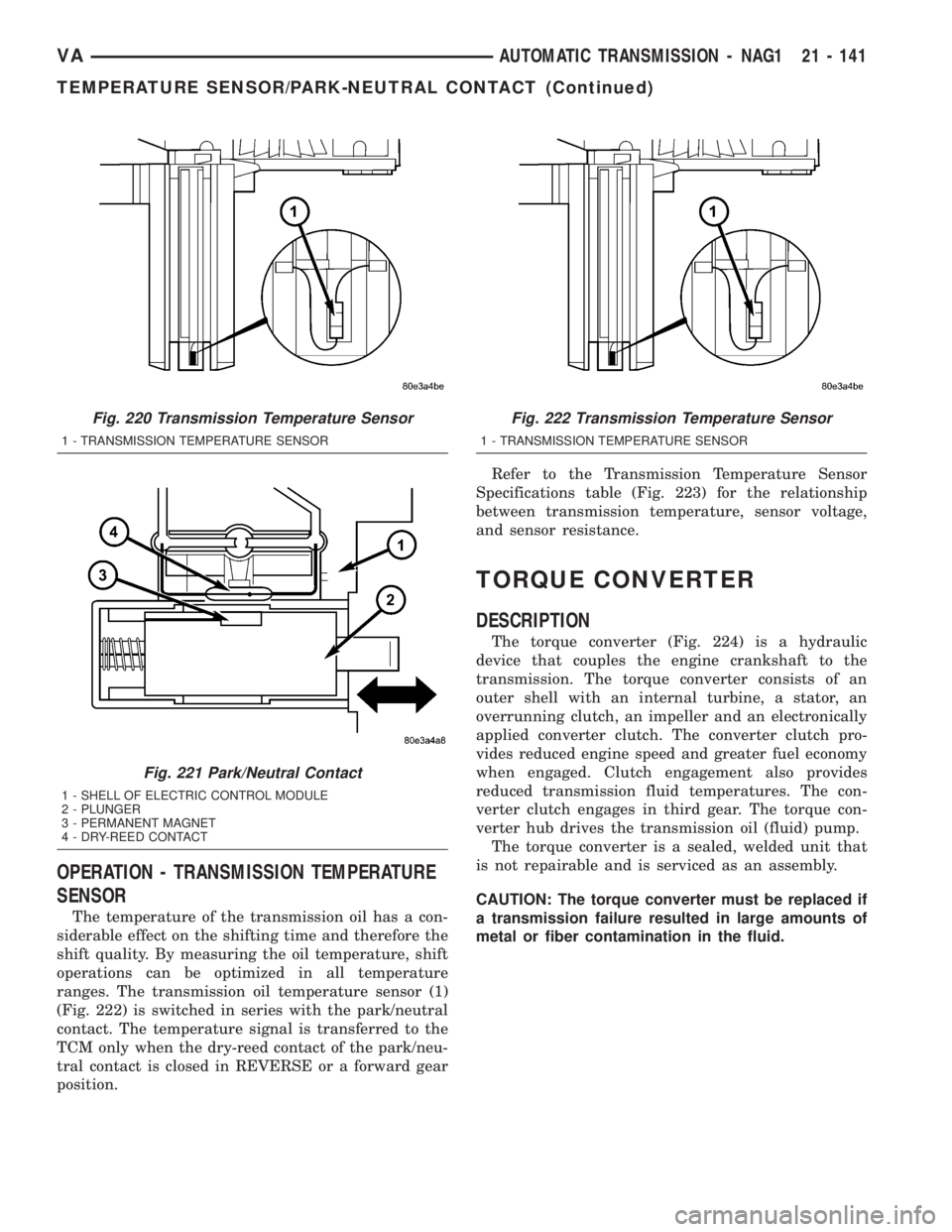
OPERATION - TRANSMISSION TEMPERATURE
SENSOR
The temperature of the transmission oil has a con-
siderable effect on the shifting time and therefore the
shift quality. By measuring the oil temperature, shift
operations can be optimized in all temperature
ranges. The transmission oil temperature sensor (1)
(Fig. 222) is switched in series with the park/neutral
contact. The temperature signal is transferred to the
TCM only when the dry-reed contact of the park/neu-
tral contact is closed in REVERSE or a forward gear
position.Refer to the Transmission Temperature Sensor
Specifications table (Fig. 223) for the relationship
between transmission temperature, sensor voltage,
and sensor resistance.
TORQUE CONVERTER
DESCRIPTION
The torque converter (Fig. 224) is a hydraulic
device that couples the engine crankshaft to the
transmission. The torque converter consists of an
outer shell with an internal turbine, a stator, an
overrunning clutch, an impeller and an electronically
applied converter clutch. The converter clutch pro-
vides reduced engine speed and greater fuel economy
when engaged. Clutch engagement also provides
reduced transmission fluid temperatures. The con-
verter clutch engages in third gear. The torque con-
verter hub drives the transmission oil (fluid) pump.
The torque converter is a sealed, welded unit that
is not repairable and is serviced as an assembly.
CAUTION: The torque converter must be replaced if
a transmission failure resulted in large amounts of
metal or fiber contamination in the fluid.
Fig. 220 Transmission Temperature Sensor
1 - TRANSMISSION TEMPERATURE SENSOR
Fig. 221 Park/Neutral Contact
1 - SHELL OF ELECTRIC CONTROL MODULE
2 - PLUNGER
3 - PERMANENT MAGNET
4 - DRY-REED CONTACT
Fig. 222 Transmission Temperature Sensor
1 - TRANSMISSION TEMPERATURE SENSOR
VAAUTOMATIC TRANSMISSION - NAG1 21 - 141
TEMPERATURE SENSOR/PARK-NEUTRAL CONTACT (Continued)
Page 1200 of 1232
CABIN HEATER
TABLE OF CONTENTS
page page
CABIN HEATER
DESCRIPTION.........................72
OPERATION...........................72
DIAGNOSIS AND TESTING - DIESEL
SUPPLEMENTAL HEATER - DCHA........72
EXHAUST TUBE
REMOVAL.............................73
INSTALLATION.........................73
FUEL DOSING PUMP
DESCRIPTION.........................74
OPERATION...........................74
REMOVAL.............................74
INSTALLATION.........................74
FUEL LINE
STANDARD PROCEDURE - CLEANING......75REMOVAL.............................75
INSTALLATION.........................76
HEATER UNIT
REMOVAL
REMOVAL...........................77
REMOVAL...........................77
INSTALLATION
INSTALLATION.......................78
INSTALLATION.......................78
INLET HOSE
REMOVAL.............................78
INSTALLATION.........................78
CABIN HEATER
DESCRIPTION
Vehicles equipped with the optional diesel engine
are also equipped with a supplemental heater unit.
This unit is mounted under the vehicle and operates
similar to an oil fired furnace. The heater burns
small amounts of fuel to provide additional heat to
the coolant. Coolant is routed from the engine, to the
supplemental heater, and then to the front heater
core. This provides additional heat to the passenger
compartment. The system is interfaced to the vehi-
cles on-board computer systems and DRBIIItdiag-
nostics.
The supplemental heater unit has an electronic
control module that monitors the heat output of the
heater. The heater operates at full load (5 kW), half
load or idle mode (no additional heat) depending on
coolant temperature.
OPERATION
The supplemental heater is activated via the tem-
perature control on the heater-A/C control. The
heater is activated when the temperature control is
set to/or above the upper set point. The supplemental
heater can operate in a full or partial load range aswell as an idle mode, all dependent on the engine
coolant temperature. The heater unit will also turn
off if the temperature control is set to less than the
lower set point. The supplemental heater can take up
to three minutes to completely shut down when
either the heater temperature is set below the lower
set point or the vehicle ignition is turned off.
The supplemental heater only operates when the
engine is running, the mileage exceeds 8 kilometer (5
mph) and the fuel tank volume exceeds 1/8 of a tank.
The heater should start if the coolant temperature is
below 40É C (104É F).
NOTE: Do not apply a strong vacuum directly on
the supplemental heater exhaust line. Place the vac-
uum within 75 mm (3 inches) of the exhaust port.
Too strong of a vacuum can prevent the heater from
starting. The heater control module monitors the
supplemental blower speed and combustion during
its start-up.DIAGNOSIS AND TESTING - DIESEL
SUPPLEMENTAL HEATER - DCHA
Refer to the Symptoms Diagnosis table for basic
checks of the diesel fueled supplemental heater.
24 - 72 CABIN HEATERVA