adding oil MERCEDES-BENZ SPRINTER 2005 Service Repair Manual
[x] Cancel search | Manufacturer: MERCEDES-BENZ, Model Year: 2005, Model line: SPRINTER, Model: MERCEDES-BENZ SPRINTER 2005Pages: 1232, PDF Size: 39.23 MB
Page 17 of 1232
If the Engine is Damaged
For towing distances up to 30 miles (about 50
km)
²Shift selector lever in ªNº position.
²Do not exceed a towing speed of 30 m.p.h. (50
km/h).
For towing distances greater than 30 mile
(about 50 km)
²Remove the propeller shafts leading to the drive
axles. The vehicle can be towed without restriction.
If the Transmission is Damaged
²Remove the propeller shafts leading to the drive
axles. The vehicle can be towed without restriction.
If the Front Axle is Damaged
²Raise the front axle.
²Observe the same towing restrictions as for
engine damage.
If the Rear Axle is Damaged
²Raise the rear axle.
NOTE: Comply with local legal regulations regard-
ing towing vehicles.
SAFETY PRECAUTIONS
NOTE: The following safety precautions must be
observed when towing a vehicle.
²Secure loose and protruding parts.
²Always use a safety chain system that is inde-
pendent of the lifting and towing equipment.
²Do not allow towing equipment to contact the
disabled vehicle's fuel tank.
²Do not allow anyone under the disabled vehicle
while it is lifted by the towing device.
²Do not allow passengers to ride in a vehicle
being towed.
²Always observe state and local laws regarding
towing regulations.
²Do not tow a vehicle in a manner that could
jeopardize the safety of the operator, pedestrians or
other motorists.
²Do not attach tow chains, T-hooks, J-hooks, or a
tow sling to a bumper, steering linkage, drive shafts
or a non-reinforced frame hole.
²Remove exhaust pipe tips that interfere with the
tow sling and crossbar
²Padding should be placed between the tow sling/
crossbar and any painted surfaces
²When placing tow hooks on the rear axle, posi-
tion them so they do not damage the brake tubing or
hoses²Do not tow the vehicle by connecting to the front
or rear shock absorbers
²Do not tow a heavily loaded vehicle. Damage to
the vehicle may result. Use a flatbed device to trans-
port a loaded vehicle.
GROUND CLEARANCE
CAUTION: If vehicle is towed with wheels removed,
install lug nuts to retain brake drums.
A towed vehicle should be raised until lifted wheels
are a minimum 100 mm (4 in) from the ground. Be
sure there is adequate ground clearance at the oppo-
site end of the vehicle, especially when towing over
rough terrain, steep rises in the road or if the vehicle
is equipped with air dams, spoilers, and/or ground
effect panels. If necessary, remove the wheels from
the lifted end of the vehicle and lower the vehicle
closer to the ground, to increase the ground clearance
at the opposite end of the vehicle. Install lug nuts on
wheel attaching studs to retain brake drums.
RAMP ANGLE
If a vehicle with flat-bed towing equipment is used,
the approach ramp angle should not exceed 15
degrees.
TOWING WHEN KEYS ARE NOT AVAILABLE
When the vehicle is locked and keys are not avail-
able, use a flat bed hauler. A Wheel-lift or Sling-type
device can be used provided all the wheels are lifted
off the ground using tow dollies.
MAINTENANCE SCHEDULES
DESCRIPTION
The use of Special lubricant additives is not recom-
mended. The use of such additives may affect the
warranty rights. With regard to legal stipulations
concerning emissions control, please note that
engines have to be serviced and adjusted in accor-
dance with special instructions and using special
measuring equipment. Modifications to or interfer-
ence with the emissions control systems are not per-
missible.
MAINTENANCE - WITHOUT ASSYST
MAINTENANCE COMPUTER
Maintenance Intervals
²Oil service ±Normal Operationevery 10,000
miles or 16,000 km or 12 months.
²Maintenance service every 20,000 miles or
32,000 km.
Additional work must be carried out at yearly
intervals.
VALUBRICATION & MAINTENANCE 0 - 7
TOWING (Continued)
Page 105 of 1232
ENGINE
TABLE OF CONTENTS
page page
COOLANT
DESCRIPTION..........................9
DIAGNOSIS AND TESTING - COOLING
SYSTEM LEAKS......................10
STANDARD PROCEDURE
STANDARD PROCEDURE - ADDING
ADDITIONAL COOLANT.................11
STANDARD PROCEDURE - DRAINING
COOLING SYSTEM....................12
STANDARD PROCEDURE - REFILLING
COOLING SYSTEM....................12
COOLANT LEVEL SENSOR
REMOVAL.............................13
INSTALLATION.........................13
RADIATOR FAN
REMOVAL.............................13
INSTALLATION.........................13
ENGINE BLOCK HEATER
REMOVAL.............................14
INSTALLATION.........................14
ENGINE COOLANT TEMP SENSOR
DESCRIPTION.........................14REMOVAL.............................14
INSTALLATION.........................15
ENGINE COOLANT THERMOSTAT
REMOVAL.............................15
INSTALLATION.........................16
FAN DRIVE VISCOUS CLUTCH
REMOVAL.............................16
INSTALLATION.........................16
RADIATOR
REMOVAL.............................16
INSTALLATION.........................17
RADIATOR PRESSURE CAP
DESCRIPTION.........................18
OPERATION...........................18
DIAGNOSIS AND TESTING - RADIATOR
PRESSURE CAP......................19
WATER PUMP
REMOVAL.............................19
INSTALLATION.........................20
COOLANT
DESCRIPTION
Coolant flows through the engine water jackets and
cylinder heads absorbing heat produced by the engine
during operation. The coolant carries heat to the radia-
tor and heater core. Here it is transferred to ambient
air passing through the radiator and heater core fins.
The required ethylene-glycol (antifreeze) and water
mixture depends upon the climate and vehicle oper-
ating conditions. The recommended mixture of 50/50
ethylene-glycol and water will provide protection
against freezing to -37 deg. C (-35 deg. F). The anti-
freeze concentrationmust alwaysbe a minimum of
44 percent, year-round in all climates.If percentage
is lower than 44 percent, engine parts may be
eroded by cavitation, and cooling system com-
ponents may be severely damaged by corrosion.
Maximum protection against freezing is provided
with a 68 percent antifreeze concentration, which
prevents freezing down to -67.7 deg. C (-90 deg. F). A
higher percentage will freeze at a warmer tempera-
ture. Also, a higher percentage of antifreeze can
cause the engine to overheat because the specific
heat of antifreeze is lower than that of water.100 Percent Ethylene-GlycolÐShould Not Be Used in
Chrysler Vehicles
Use of 100 percent ethylene-glycol will cause forma-
tion of additive deposits in the system, as the corrosion
inhibitive additives in ethylene-glycol require the pres-
ence of water to dissolve. The deposits act as insulation,
causing temperatures to rise to as high as 149 deg. C
(300 deg. F). This temperature is hot enough to melt
plastic and soften solder. The increased temperature can
result in engine detonation. In addition, 100 percent
ethylene-glycol freezes at -22 deg. C (-8 deg. F ).
Propylene-glycol FormulationsÐShould Not Be Used in
Chrysler Vehicles
Propylene-glycol formulations do not meet
Chrysler coolant specifications.
It's overall effec-
tive temperature range is smaller than that of ethylene-
glycol. The freeze point of 50/50 propylene-glycol and
water is -32 deg. C (-26 deg. F). 5 deg. C higher than
ethylene-glycol's freeze point. The boiling point (protec-
tion against summer boil-over) of propylene-glycol is 125
deg. C (257 deg.F)at96.5 kPa (14 psi), compared to
128 deg. C (263 deg. F) for ethylene-glycol. Use of pro-
pylene-glycol can result in boil-over or freeze-up in
Chrysler vehicles, which are designed for ethylene-gly-
col. Propylene glycol also has poorer heat transfer char-
VAENGINE 7 - 9
Page 107 of 1232
Operate tester pump to apply 103.4 kPa (15 psi)
pressure to system. If hoses enlarge excessively or
bulges while testing, replace as necessary. Observe
gauge pointer and determine condition of cooling sys-
tem according to following criteria:
Holds Steady:If pointer remains steady for two
minutes, serious coolant leaks are not present in sys-
tem. However, there could be an internal leak that
does not appear with normal system test pressure. If
it is certain that coolant is being lost and leaks can-
not be detected, inspect for interior leakage or per-
form Internal Leakage Test.
Drops Slowly:Indicates a small leak or seepage
is occurring. Examine all connections for seepage or
slight leakage with a flashlight. Inspect radiator,
hoses, gasket edges and heater. Seal small leak holes
with a Sealer Lubricant (or equivalent). Repair leak
holes and inspect system again with pressure
applied.
Drops Quickly:Indicates that serious leakage is
occurring. Examine system for external leakage. If
leaks are not visible, inspect for internal leakage.
Large radiator leak holes should be repaired by a
reputable radiator repair shop.
INTERNAL LEAKAGE INSPECTION
Remove engine oil pan drain plug and drain a
small amount of engine oil. If coolant is present in
the pan, it will drain first because it is heavier than
oil. An alternative method is to operate engine for a
short period to churn the oil. After this is done,
remove engine dipstick and inspect for water glob-
ules. Also inspect transmission dipstick for water
globules and transmission fluid cooler for leakage.
WARNING: WITH RADIATOR PRESSURE TESTER
TOOL INSTALLED ON RADIATOR, DO NOT ALLOW
PRESSURE TO EXCEED 110 KPA (20 PSI). PRES-
SURE WILL BUILD UP QUICKLY IF A COMBUSTION
LEAK IS PRESENT. TO RELEASE PRESSURE,
ROCK TESTER FROM SIDE TO SIDE. WHEN
REMOVING TESTER, DO NOT TURN TESTER MORE
THAN 1/2 TURN IF SYSTEM IS UNDER PRESSURE.
Operate engine without pressure cap on coolant
container until thermostat opens. Attach a Pressure
Tester to container. If pressure builds up quickly it
indicates a combustion leak exists. This is usually
the result of a cylinder head gasket leak or crack in
engine. Repair as necessary.
If there is not an immediate pressure increase,
pump the Pressure Tester. Do this until indicated
pressure is within system range of 110 kPa (16 psi).
Fluctuation of gauge pointer indicates compression or
combustion leakage into cooling system.Because the vehicle is equipped with a catalytic
converter,do notremove spark plug cables or short
out cylinders to isolate compression leak.
If the needle on dial of pressure tester does not
fluctuate, race engine a few times to check for an
abnormal amount of coolant or steam. This would be
emitting from exhaust pipe. Coolant or steam from
exhaust pipe may indicate a faulty cylinder head gas-
ket, cracked engine cylinder block or cylinder head.
A convenient check for exhaust gas leakage into
cooling system is provided by a commercially avail-
able Block Leak Check tool. Follow manufacturers
instructions when using this product.
COMBUSTION LEAKAGE TEST - WITHOUT
PRESSURE TESTER
DO NOT WASTE reusable coolant. If solution is
clean, drain coolant into a clean and suitably marked
container for reuse.
WARNING: DO NOT REMOVE CYLINDER BLOCK
DRAIN PLUGS OR LOOSEN RADIATOR DRAIN
WITH SYSTEM HOT AND UNDER PRESSURE. SERI-
OUS BURNS FROM COOLANT CAN OCCUR.
Drain sufficient coolant to allow thermostat removal.
Remove accessory drive belt.
Add coolant to pressure container to bring level to
within 6.3 mm (1/4 in) of top of thermostat housing.
CAUTION: Avoid overheating. Do not operate
engine for an excessive period of time. Open drain-
cock immediately after test to eliminate boil over.
Start engine and accelerate rapidly three times, to
approximately 3000 rpm while observing coolant. If
internal engine combustion gases are leaking into
cooling system, bubbles will appear in coolant. If bub-
bles do not appear, internal combustion gas leakage
is not present.
STANDARD PROCEDURE
STANDARD PROCEDURE - ADDING
ADDITIONAL COOLANT
The use of aluminum cylinder blocks, cylinder
heads and water pumps requires special corrosion
protection. Only MopartAntifreeze/Coolant, 5
Year/100,000 Mile Formula (glycol base coolant with
corrosion inhibitors called HOAT, for Hybrid Organic
Additive Technology) is recommended. This coolant
offers the best engine cooling without corrosion when
mixed with 50% distilled water to obtain to obtain a
freeze point of -37ÉC (-35ÉF). If it loses color or
becomes contaminated, drain, flush, and replace with
fresh properly mixed coolant solution.
VAENGINE 7 - 11
COOLANT (Continued)
Page 978 of 1232
DIAGNOSIS AND TESTING
DIAGNOSIS AND TESTING - EFFECTS OF
INCORRECT FLUID LEVEL
A low fluid level allows the pump to take in air
along with the fluid. Air in the fluid will cause fluid
pressures to be low and develop slower than normal.
If the transmission is overfilled, the gears churn the
fluid into foam. This aerates the fluid and causing
the same conditions occurring with a low level. In
either case, air bubbles cause fluid overheating, oxi-
dation and varnish buildup which interferes with
valve and clutch operation. Foaming also causes fluid
expansion which can result in fluid overflow from the
transmission vent or fill tube. Fluid overflow can eas-
ily be mistaken for a leak if inspection is not careful.
DIAGNOSIS AND TESTING - CAUSES OF
BURNT FLUID
Burnt, discolored fluid is a result of overheating
which has three primary causes.
(1) Internal clutch slippage, usually caused by low
line pressure, inadequate clutch apply pressure, or
clutch seal failure.
(2) A result of restricted fluid flow through the
main and/or auxiliary cooler. This condition is usu-
ally the result of a faulty or improperly installed
drainback valve, a damaged main cooler, or severe
restrictions in the coolers and lines caused by debris
or kinked lines.
(3) Heavy duty operation with a vehicle not prop-
erly equipped for this type of operation. Trailer tow-
ing or similar high load operation will overheat the
transmission fluid if the vehicle is improperly
equipped. Such vehicles should have an auxiliary
transmission fluid cooler, a heavy duty cooling sys-
tem, and the engine/axle ratio combination needed to
handle heavy loads.
DIAGNOSIS AND TESTING - FLUID
CONTAMINATION
Transmission fluid contamination is generally a
result of:
²adding incorrect fluid
²failure to clean dipstick and fill tube when
checking level
²engine coolant entering the fluid
²internal failure that generates debris
²overheat that generates sludge (fluid break-
down)
²failure to replace contaminated converter after
repair
The use of non-recommended fluids can result in
transmission failure. The usual results are erratic
shifts, slippage, abnormal wear and eventual failuredue to fluid breakdown and sludge formation. Avoid
this condition by using recommended fluids only.
The dipstick cap and fill tube should be wiped
clean before checking fluid level. Dirt, grease and
other foreign material on the cap and tube could fall
into the tube if not removed beforehand. Take the
time to wipe the cap and tube clean before withdraw-
ing the dipstick.
Engine coolant in the transmission fluid is gener-
ally caused by a cooler malfunction. The only remedy
is to replace the radiator as the cooler in the radiator
is not a serviceable part. If coolant has circulated
through the transmission, an overhaul is necessary.
The torque converter should be replaced whenever
a failure generates sludge and debris. This is neces-
sary because normal converter flushing procedures
will not remove all contaminants.
STANDARD PROCEDURE
STANDARD PROCEDURE - CHECK OIL LEVEL
(1) Verify that the vehicle is parked on a level sur-
face.
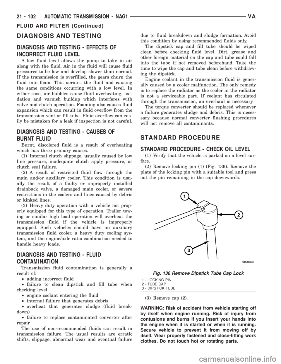
(2) Remove locking pin (1) (Fig. 136). Remove the
plate of the locking pin with a suitable tool and press
out the pin remaining in the cap downwards.
(3) Remove cap (2).
WARNING: Risk of accident from vehicle starting off
by itself when engine running. Risk of injury from
contusions and burns if you insert your hands into
the engine when it is started or when it is running.
Secure vehicle to prevent it from moving off by
itself. Wear properly fastened and close-fitting work
clothes. Do not touch hot or rotating parts.
Fig. 136 Remove Dipstick Tube Cap Lock
1 - LOCKING PIN
2 - TUBE CAP
3 - DIPSTICK TUBE
21 - 102 AUTOMATIC TRANSMISSION - NAG1VA
FLUID AND FILTER (Continued)
Page 1042 of 1232
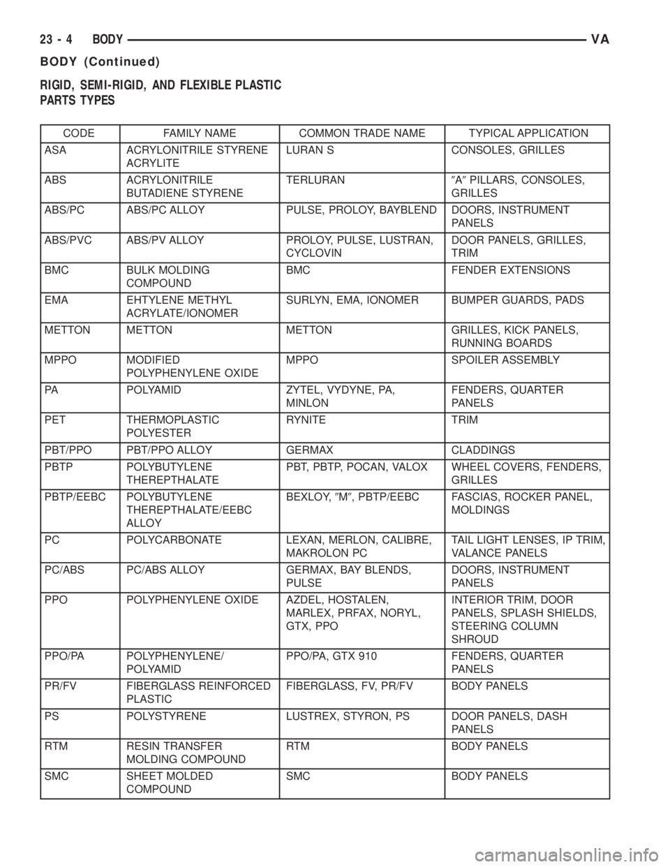
RIGID, SEMI-RIGID, AND FLEXIBLE PLASTIC
PARTS TYPES
CODE FAMILY NAME COMMON TRADE NAME TYPICAL APPLICATION
ASA ACRYLONITRILE STYRENE
ACRYLITELURAN S CONSOLES, GRILLES
ABS ACRYLONITRILE
BUTADIENE STYRENETERLURAN9A9PILLARS, CONSOLES,
GRILLES
ABS/PC ABS/PC ALLOY PULSE, PROLOY, BAYBLEND DOORS, INSTRUMENT
PANELS
ABS/PVC ABS/PV ALLOY PROLOY, PULSE, LUSTRAN,
CYCLOVINDOOR PANELS, GRILLES,
TRIM
BMC BULK MOLDING
COMPOUNDBMC FENDER EXTENSIONS
EMA EHTYLENE METHYL
ACRYLATE/IONOMERSURLYN, EMA, IONOMER BUMPER GUARDS, PADS
METTON METTON METTON GRILLES, KICK PANELS,
RUNNING BOARDS
MPPO MODIFIED
POLYPHENYLENE OXIDEMPPO SPOILER ASSEMBLY
PA POLYAMID ZYTEL, VYDYNE, PA,
MINLONFENDERS, QUARTER
PANELS
PET THERMOPLASTIC
POLYESTERRYNITE TRIM
PBT/PPO PBT/PPO ALLOY GERMAX CLADDINGS
PBTP POLYBUTYLENE
THEREPTHALATEPBT, PBTP, POCAN, VALOX WHEEL COVERS, FENDERS,
GRILLES
PBTP/EEBC POLYBUTYLENE
THEREPTHALATE/EEBC
ALLOYBEXLOY,9M9, PBTP/EEBC FASCIAS, ROCKER PANEL,
MOLDINGS
PC POLYCARBONATE LEXAN, MERLON, CALIBRE,
MAKROLON PCTAIL LIGHT LENSES, IP TRIM,
VALANCE PANELS
PC/ABS PC/ABS ALLOY GERMAX, BAY BLENDS,
PULSEDOORS, INSTRUMENT
PANELS
PPO POLYPHENYLENE OXIDE AZDEL, HOSTALEN,
MARLEX, PRFAX, NORYL,
GTX, PPOINTERIOR TRIM, DOOR
PANELS, SPLASH SHIELDS,
STEERING COLUMN
SHROUD
PPO/PA POLYPHENYLENE/
POLYAMIDPPO/PA, GTX 910 FENDERS, QUARTER
PANELS
PR/FV FIBERGLASS REINFORCED
PLASTICFIBERGLASS, FV, PR/FV BODY PANELS
PS POLYSTYRENE LUSTREX, STYRON, PS DOOR PANELS, DASH
PANELS
RTM RESIN TRANSFER
MOLDING COMPOUNDRTM BODY PANELS
SMC SHEET MOLDED
COMPOUNDSMC BODY PANELS
23 - 4 BODYVA
BODY (Continued)
Page 1043 of 1232
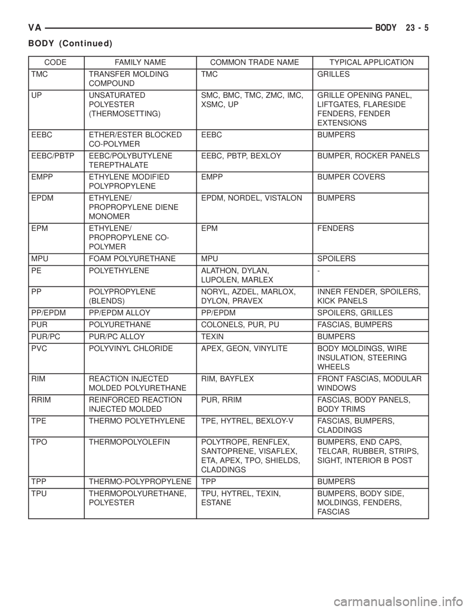
CODE FAMILY NAME COMMON TRADE NAME TYPICAL APPLICATION
TMC TRANSFER MOLDING
COMPOUNDTMC GRILLES
UP UNSATURATED
POLYESTER
(THERMOSETTING)SMC, BMC, TMC, ZMC, IMC,
XSMC, UPGRILLE OPENING PANEL,
LIFTGATES, FLARESIDE
FENDERS, FENDER
EXTENSIONS
EEBC ETHER/ESTER BLOCKED
CO-POLYMEREEBC BUMPERS
EEBC/PBTP EEBC/POLYBUTYLENE
TEREPTHALATEEEBC, PBTP, BEXLOY BUMPER, ROCKER PANELS
EMPP ETHYLENE MODIFIED
POLYPROPYLENEEMPP BUMPER COVERS
EPDM ETHYLENE/
PROPROPYLENE DIENE
MONOMEREPDM, NORDEL, VISTALON BUMPERS
EPM ETHYLENE/
PROPROPYLENE CO-
POLYMEREPM FENDERS
MPU FOAM POLYURETHANE MPU SPOILERS
PE POLYETHYLENE ALATHON, DYLAN,
LUPOLEN, MARLEX-
PP POLYPROPYLENE
(BLENDS)NORYL, AZDEL, MARLOX,
DYLON, PRAVEXINNER FENDER, SPOILERS,
KICK PANELS
PP/EPDM PP/EPDM ALLOY PP/EPDM SPOILERS, GRILLES
PUR POLYURETHANE COLONELS, PUR, PU FASCIAS, BUMPERS
PUR/PC PUR/PC ALLOY TEXIN BUMPERS
PVC POLYVINYL CHLORIDE APEX, GEON, VINYLITE BODY MOLDINGS, WIRE
INSULATION, STEERING
WHEELS
RIM REACTION INJECTED
MOLDED POLYURETHANERIM, BAYFLEX FRONT FASCIAS, MODULAR
WINDOWS
RRIM REINFORCED REACTION
INJECTED MOLDEDPUR, RRIM FASCIAS, BODY PANELS,
BODY TRIMS
TPE THERMO POLYETHYLENE TPE, HYTREL, BEXLOY-V FASCIAS, BUMPERS,
CLADDINGS
TPO THERMOPOLYOLEFIN POLYTROPE, RENFLEX,
SANTOPRENE, VISAFLEX,
ETA, APEX, TPO, SHIELDS,
CLADDINGSBUMPERS, END CAPS,
TELCAR, RUBBER, STRIPS,
SIGHT, INTERIOR B POST
TPP THERMO-POLYPROPYLENE TPP BUMPERS
TPU THERMOPOLYURETHANE,
POLYESTERTPU, HYTREL, TEXIN,
ESTANEBUMPERS, BODY SIDE,
MOLDINGS, FENDERS,
FASCIAS
VABODY 23 - 5
BODY (Continued)
Page 1176 of 1232
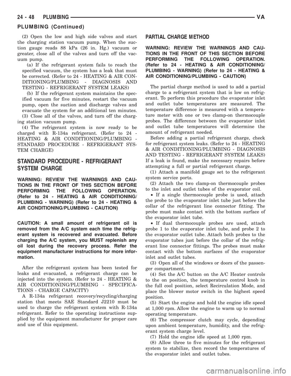
(2) Open the low and high side valves and start
the charging station vacuum pump. When the suc-
tion gauge reads 88 kPa (26 in. Hg.) vacuum or
greater, close all of the valves and turn off the vac-
uum pump.
(a) If the refrigerant system fails to reach the
specified vacuum, the system has a leak that must
be corrected. (Refer to 24 - HEATING & AIR CON-
DITIONING/PLUMBING - DIAGNOSIS AND
TESTING - REFRIGERANT SYSTEM LEAKS)
(b) If the refrigerant system maintains the spec-
ified vacuum for five minutes, restart the vacuum
pump, open the suction and discharge valves and
evacuate the system for an additional ten minutes.
(3) Close all of the valves, and turn off the charg-
ing station vacuum pump.
(4) The refrigerant system is now ready to be
charged with R-134a refrigerant. (Refer to 24 -
HEATING & AIR CONDITIONING/PLUMBING -
STANDARD PROCEDURE - REFRIGERANT SYS-
TEM CHARGE)
STANDARD PROCEDURE - REFRIGERANT
SYSTEM CHARGE
WARNING: REVIEW THE WARNINGS AND CAU-
TIONS IN THE FRONT OF THIS SECTION BEFORE
PERFORMING THE FOLLOWING OPERATION.
(Refer to 24 - HEATING & AIR CONDITIONING/
PLUMBING - WARNING) (Refer to 24 - HEATING &
AIR CONDITIONING/PLUMBING - CAUTION)
CAUTION: A small amount of refrigerant oil is
removed from the A/C system each time the refrig-
erant system is recovered and evacuated. Before
charging the A/C system, you MUST replenish any
oil lost during the recovery process. Refer the
equipment manufacturer instructions for more infor-
mation.
After the refrigerant system has been tested for
leaks and evacuated, a refrigerant charge can be
injected into the system. (Refer to 24 - HEATING &
AIR CONDITIONING/PLUMBING - SPECIFICA-
TIONS - CHARGE CAPACITY)
A R-134a refrigerant recovery/recycling/charging
station that meets SAE Standard J2210 must be
used to charge the refrigerant system with R-134a
refrigerant. Refer to the operating instructions sup-
plied by the equipment manufacturer for proper care
and use of this equipment.
PARTIAL CHARGE METHOD
WARNING: REVIEW THE WARNINGS AND CAU-
TIONS IN THE FRONT OF THIS SECTION BEFORE
PERFORMING THE FOLLOWING OPERATION.
(Refer to 24 - HEATING & AIR CONDITIONING/
PLUMBING - WARNING) (Refer to 24 - HEATING &
AIR CONDITIONING/PLUMBING - CAUTION)
The partial charge method is used to add a partial
charge to a refrigerant system that is low on refrig-
erant. To perform this procedure the evaporator inlet
and outlet tube temperatures are measured. The
temperature difference is measured with a tempera-
ture meter with one or two clamp-on thermocouple
probes. The difference between the evaporator inlet
and outlet tube temperatures will determine the
amount of refrigerant needed.
Before adding a partial refrigerant charge, check
for refrigerant system leaks. (Refer to 24 - HEATING
& AIR CONDITIONING/PLUMBING - DIAGNOSIS
AND TESTING - REFRIGERANT SYSTEM LEAKS)
If a leak is found, make the necessary repairs before
attempting a full or partial refrigerant charge.
(1) Attach a manifold gauge set to the refrigerant
system service ports.
(2) Attach the two clamp-on thermocouple probes
to the inlet and outlet tubes of the evaporator coil.
²If a single thermocouple probe is used, attach
the probe to the evaporator inlet tube just before the
collar of the refrigerant line connector fitting. The
probe must make contact with the bottom surface of
the evaporator inlet tube.
²If dual thermocouple probes are used, attach
probe 1 to the evaporator inlet tube, and probe 2 to
the evaporator outlet tube. Attach both probes to the
evaporator tubes just before the collar of the refrig-
erant line connector fittings. The probes must make
contact with the bottom surfaces of the evaporator
inlet and outlet tubes.
(3) Open all of the windows or doors of the passen-
ger compartment.
(4) Set the A/C button on the A/C Heater controls
to the on position, the temperature control knob in
the full cool position, select Recirculation Mode, and
place the blower motor switch in the highest speed
position.
(5) Start the engine and hold the engine idle speed
at 1,000 rpm. Allow the engine to warm up to normal
operating temperature.
(6) The compressor clutch may cycle, depending
upon ambient temperature, humidity, and the refrig-
erant system charge level.
(7) Hold the engine idle speed at 1,000 rpm.
(8) Allow three to five minutes for the refrigerant
system to stabilize, then record the temperatures of
the evaporator inlet and outlet tubes.
24 - 48 PLUMBINGVA
PLUMBING (Continued)
Page 1214 of 1232
CIRCUIT BREAKER - OPERATION......8W-97-2
CIRCUIT INFORMATION - DESCRIPTION . 8W-01-5
CLAMP PLATES - INSTALLATION,
SPRING..............................2-8
CLAMP PLATES - REMOVAL, SPRING......2-8
CLASSIFICATION - STANDARD
PROCEDURE, INJECTOR...............14-22
CLEARANCE LAMP BULB -
INSTALLATION........................8L-8
CLEARANCE LAMP BULB - REMOVAL.....8L-8
CLEARANCE LAMP UNIT -
INSTALLATION........................8L-9
CLEARANCE LAMP UNIT - REMOVAL......8L-8
CLOCK - DESCRIPTION................8J-13
CLOCK - OPERATION..................8J-14
CLOCKSPRING - DESCRIPTION.........8O-12
CLOCKSPRING - INSTALLATION.........8O-15
CLOCKSPRING - OPERATION...........8O-13
CLOCKSPRING - REMOVAL............8O-14
CLOCKSPRING CENTERING - STANDARD
PROCEDURE........................8O-13
CLOGGED INDICATOR - DESCRIPTION,
FUEL FILTER........................8J-15
CLOGGED INDICATOR - OPERATION,
FUEL FILTER........................8J-15
CLUSTER - DESCRIPTION, INSTRUMENT . . . 8J-2
CLUSTER - DIAGNOSIS AND TESTING,
INSTRUMENT........................8J-7
CLUSTER - INSTALLATION, INSTRUMENT . . 8J-9
CLUSTER - INSTALLATION, TOP COVER . . . 23-62
CLUSTER - OPERATION, INSTRUMENT.....8J-5
CLUSTER - REMOVAL, INSTRUMENT......8J-7
CLUSTER - REMOVAL, TOP COVER......23-62
CLUSTER BEZEL - INSTALLATION........23-54
CLUSTER BEZEL - REMOVAL...........23-53
CLUTCH - ASSEMBLY, FREEWHEELING . . 21-107
CLUTCH - DESCRIPTION, A/C
COMPRESSOR........................24-8
CLUTCH - DESCRIPTION,
FREEWHEELING.....................21-105
CLUTCH - DISASSEMBLY,
FREEWHEELING.....................21-106
CLUTCH - INSTALLATION, FAN DRIVE
VISCOUS............................7-16
CLUTCH - OPERATION, A/C
COMPRESSOR........................24-8
CLUTCH - OPERATION, FREEWHEELING . . 21-105
CLUTCH - REMOVAL, FAN DRIVE
VISCOUS............................7-16
CLUTCH AIR GAP - STANDARD
PROCEDURE, COMPRESSOR............24-9
CLUTCH B1 - ASSEMBLY, HOLDING.....21-113
CLUTCH B1 - DISASSEMBLY, HOLDING . . 21-112
CLUTCH B2 - ASSEMBLY, HOLDING.....21-116
CLUTCH B2 - DISASSEMBLY, HOLDING . . 21-115
CLUTCH BREAK-IN - STANDARD
PROCEDURE, COMPRESSOR............24-9
CLUTCH COIL - DIAGNOSIS AND
TESTING, COMPRESSOR...............24-12
CLUTCH K1 - ASSEMBLY, DRIVING.......21-75
CLUTCH K1 - DISASSEMBLY, DRIVING....21-74
CLUTCH K2 - ASSEMBLY, DRIVING.......21-78
CLUTCH K2 - DISASSEMBLY, DRIVING....21-76
CLUTCH K3 - ASSEMBLY, DRIVING.......21-80
CLUTCH K3 - DISASSEMBLY, DRIVING....21-80
CLUTCH/COIL - INSPECTION,
COMPRESSOR.......................24-10
CLUTCHES - DESCRIPTION, DRIVING.....21-72
CLUTCHES - DESCRIPTION, HOLDING . . . 21-111
CLUTCHES - OPERATION, DRIVING......21-72
CLUTCHES - OPERATION, HOLDING.....21-112
CODES - SPECIFICATIONS, PAINT........23-74
COIL - DIAGNOSIS AND TESTING,
COMPRESSOR CLUTCH...............24-12
COLUMN OPENING COVER -
INSTALLATION, STEERING.............23-66
COLUMN OPENING COVER - REMOVAL,
STEERING..........................23-66
COMPRESSION TESTING ENGINE -
STANDARD PROCEDURE.................9-3
COMPRESSOR - DESCRIPTION, A/C......24-49
COMPRESSOR - INSTALLATION, A/C
.....24-51
COMPRESSOR - OPERATION, A/C
........24-49
COMPRESSOR - REMOVAL, A/C
.........24-50
COMPRESSOR CLUTCH - DESCRIPTION,
A/C
................................24-8
COMPRESSOR CLUTCH - OPERATION,
A/C
................................24-8COMPRESSOR CLUTCH AIR GAP -
STANDARD PROCEDURE................24-9
COMPRESSOR CLUTCH BREAK-IN -
STANDARD PROCEDURE................24-9
COMPRESSOR CLUTCH COIL -
DIAGNOSIS AND TESTING.............24-12
COMPRESSOR CLUTCH/COIL -
INSPECTION........................24-10
COMPRESSOR NOISE - DIAGNOSIS AND
TESTING...........................24-49
CONDENSER - DESCRIPTION, A/C.......24-52
CONDENSER - INSTALLATION, A/C.......24-52
CONDENSER - OPERATION, A/C.........24-52
CONDENSER - REMOVAL, A/C..........24-52
CONDITIONER - DESCRIPTION, HEATER
AND AIR ............................24-1
CONDITIONER - OPERATION, HEATER
AND AIR ............................24-2
CONNECTING FUEL LINES - STANDARD
PROCEDURE, DISCONNECTING...........14-2
CONNECTING ROD - DESCRIPTION,
PISTON.............................9-40
CONNECTING RODS - STANDARD
PROCEDURE, CHECKING AND
REPAIRING..........................9-40
CONNECTOR - INSTALLATION........8W-01-9
CONNECTOR - REMOVAL............8W-01-8
CONNECTOR, GROUND AND SPLICE
INFORMATION - DESCRIPTION........8W-01-5
CONNECTOR/GROUND/SPLICE LOCATION
- DESCRIPTION....................8W-91-1
CONTACT - DESCRIPTION, PARK/
NEUTRAL..........................21-139
CONTACT - OPERATION, PARK/NEUTRAL . 21-140
CONTAMINATION - DIAGNOSIS AND
TESTING, BRAKE FLUID................5-14
CONTAMINATION - DIAGNOSIS AND
TESTING, FLUID....................21-102
CONTINUITY - STANDARD PROCEDURE,
TESTING.........................8W-01-8
CONTROL ARM - INSTALLATION, LOWER . . . 2-6
CONTROL ARM - REMOVAL, LOWER.......2-6
CONTROL INDICATOR - DESCRIPTION,
TRACTION..........................8J-24
CONTROL INDICATOR - OPERATION,
TRACTION..........................8J-24
CONTROL MALFUNCTION INDICATOR -
DESCRIPTION, TRACTION..............8J-25
CONTROL MALFUNCTION INDICATOR -
OPERATION, TRACTION................8J-25
CONTROL MODULE - DESCRIPTION......24-24
CONTROL MODULE - DESCRIPTION,
AIRBAG.............................8O-8
CONTROL MODULE - DESCRIPTION,
ENGINE.............................8E-3
CONTROL MODULE - DESCRIPTION,
TRANSMISSION.......................8E-5
CONTROL MODULE - DIAGNOSIS AND
TESTING...........................24-24
CONTROL MODULE - INSTALLATION.....24-25
CONTROL MODULE - INSTALLATION,
AIRBAG............................8O-11
CONTROL MODULE - INSTALLATION,
ENGINE.............................8E-4
CONTROL MODULE - OPERATION.......24-24
CONTROL MODULE - OPERATION,
AIRBAG.............................8O-9
CONTROL MODULE - OPERATION,
TRANSMISSION.......................8E-5
CONTROL MODULE - REMOVAL.........24-24
CONTROL MODULE - REMOVAL, AIRBAG . 8O-10
CONTROL MODULE - REMOVAL, ENGINE . . . 8E-4
CONTROLLER - INSTALLATION, ALB......5-15
CONTROLLER - REMOVAL, ALB..........5-15
CONTROLLER ANTILOCK BRAKE -
DESCRIPTION........................8E-3
CONTROLLER ANTILOCK BRAKE -
INSTALLATION........................8E-3
CONTROLLER ANTILOCK BRAKE -
REMOVAL...........................8E-3
CONVERTER - DESCRIPTION, TORQUE . . . 21-141
CONVERTER - INSTALLATION, CATALYTIC . . 11-3
CONVERTER - INSTALLATION, TORQUE
. . 21-146
CONVERTER - OPERATION, TORQUE
....21-143
CONVERTER - REMOVAL, CATALYTIC
......11-3
CONVERTER - REMOVAL, TORQUE
......21-146
CONVERTER HUB SEAL - INSTALLATION,
TORQUE
...........................21-147CONVERTER HUB SEAL - REMOVAL,
TORQUE...........................21-147
COOLANT - DESCRIPTION...............7-9
COOLANT - DESCRIPTION, ENGINE........0-1
COOLANT - DESCRIPTION, HOAT..........0-2
COOLANT - STANDARD PROCEDURE,
ADDING ADDITIONAL..................7-11
COOLANT LEVEL SENSOR -
INSTALLATION........................7-13
COOLANT LEVEL SENSOR - REMOVAL.....7-13
COOLANT LOW INDICATOR -
DESCRIPTION.......................8J-14
COOLANT LOW INDICATOR - OPERATION . 8J-14
COOLANT PUMP - DESCRIPTION,
ELECTRIC..........................24-57
COOLANT PUMP - INSTALLATION,
ELECTRIC..........................24-57
COOLANT PUMP - OPERATION,
ELECTRIC..........................24-57
COOLANT PUMP - REMOVAL, ELECTRIC . . 24-57
COOLANT TEMP SENSOR -
DESCRIPTION, ENGINE.................7-14
COOLANT TEMP SENSOR -
INSTALLATION, ENGINE................7-15
COOLANT TEMP SENSOR - REMOVAL,
ENGINE.............................7-14
COOLANT THERMOSTAT -
INSTALLATION, ENGINE................7-16
COOLANT THERMOSTAT - REMOVAL,
ENGINE.............................7-15
COOLER & LINES - INSTALLATION, OIL....9-50
COOLER & LINES - REMOVAL, OIL.......9-50
COOLER AND PLUMBING - CLEANING,
CHARGE AIR.........................11-5
COOLER AND PLUMBING -
DESCRIPTION, CHARGE AIR.............11-4
COOLER AND PLUMBING - INSPECTION,
CHARGE AIR.........................11-5
COOLER AND PLUMBING -
INSTALLATION, CHARGE AIR............11-5
COOLER AND PLUMBING - OPERATION,
CHARGE AIR.........................11-4
COOLER AND PLUMBING - REMOVAL,
CHARGE AIR.........................11-5
COOLER SYSTEM - LEAKS - DIAGNOSIS
AND TESTING, CHARGE AIR.............11-4
COOLER TUBE - INSTALLATION, FLUID . . . 19-14
COOLER TUBE - INSTALLATION, RETURN
HOSE FROM GEAR TO................19-15
COOLER TUBE - INSTALLATION, RETURN
LINE FROM PUMP TO.................19-15
COOLER TUBE - REMOVAL, FLUID.......19-14
COOLER TUBE - REMOVAL, RETURN
HOSE FROM GEAR TO................19-15
COOLER TUBE - REMOVAL, RETURN
LINE FROM PUMP TO.................19-15
COOLING SYSTEM - DIAGNOSIS AND
TESTING.............................7-2
COOLING SYSTEM - OPERATION..........7-1
COOLING SYSTEM - STANDARD
PROCEDURE, DRAINING................7-12
COOLING SYSTEM - STANDARD
PROCEDURE, REFILLING................7-12
COOLING SYSTEM LEAKS - DIAGNOSIS
AND TESTING........................7-10
COOLING SYSTEM REQUIREMENTS -
DESCRIPTION........................24-1
CORE - DESCRIPTION, HEATER.........24-57
CORE - INSTALLATION, HEATER.........24-58
CORE - OPERATION, HEATER...........24-57
CORE - REMOVAL, HEATER............24-58
CORE AND OIL GALLERY PLUGS -
STANDARD PROCEDURE, REPLACING
ENGINE.............................9-34
COVER - CLUSTER - INSTALLATION, TOP . 23-62
COVER - CLUSTER - REMOVAL, TOP.....23-62
COVER - INSTALLATION, CYLINDER
HEAD FRONT.........................9-26
COVER - INSTALLATION, ENGINE..........9-7
COVER - INSTALLATION, STEERING
COLUMN OPENING...................23-66
COVER - INSTALLATION, TIMING CHAIN
. . . 9-60
COVER - INSTALLATION, TOP
...........23-65
COVER - REMOVAL, CYLINDER HEAD
FRONT
..............................9-23
COVER - REMOVAL, ENGINE
..............9-4
COVER - REMOVAL, STEERING COLUMN
OPENING
...........................23-66
4 INDEXVA
Description Group-Page Description Group-Page Description Group-Page