ABS MERCEDES-BENZ SPRINTER 2006 Service Manual
[x] Cancel search | Manufacturer: MERCEDES-BENZ, Model Year: 2006, Model line: SPRINTER, Model: MERCEDES-BENZ SPRINTER 2006Pages: 2305, PDF Size: 48.12 MB
Page 774 of 2305
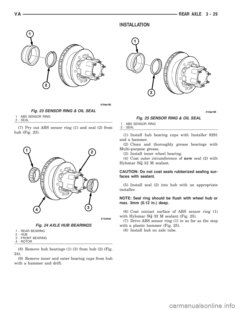
(7) Pry out ABS sensor ring (1) and seal (2) from
hub (Fig. 23).
(8) Remove hub bearings (1) (3) from hub (2) (Fig.
24).
(9) Remove inner and outer bearing cups from hub
with a hammer and drift.
INSTALLATION
(1) Install hub bearing cups with Installer 9291
and a hammer.
(2) Clean and thoroughly grease bearings with
Multi-purpose grease.
(3) Install inner wheel bearing.
(4) Coat outer circumference ofnewseal (2) with
Hylomar SQ 32 M sealant.
CAUTION: Do not coat seals rubberized sealing sur-
faces with sealant.
(5) Install seal (2) into hub with an appropriate
installer.
NOTE: Seal ring should be flush with wheel hub or
max. 3mm (0.12 in.) deep.
(6) Coat contact surface of ABS sensor ring (1)
with Hylomar SQ 32 M sealant (Fig. 25).
(7) Drive ABS sensor ring (1) in as far as the stop
with a plastic hammer (Fig. 25).
(8) Install hub on axle tube.
Fig. 23 SENSOR RING & OIL SEAL
1 - ABS SENSOR RING
2 - SEAL
Fig. 24 AXLE HUB BEARINGS
1 - REAR BEARING
2 - HUB
3 - FRONT BEARING
4 - ROTOR
Fig. 25 SENSOR RING & OIL SEAL
1 - ABS SENSOR RING
2 - SEAL
VAREAR AXLE 3 - 29
Page 790 of 2305
BRAKES
TABLE OF CONTENTS
page page
BRAKES - BASE........................... 1BRAKES - ABS........................... 30
BRAKES - BASE
TABLE OF CONTENTS
page page
BRAKES - BASE
DIAGNOSIS AND TESTING - BASE BRAKE
SYSTEM.............................2
STANDARD PROCEDURE
STANDARD PROCEDURE - MANUAL
BLEEDING............................4
STANDARD PROCEDURE - PRESSURE
BLEEDING............................5
HYDRAULIC/MECHANICAL
SPECIFICATIONS
SPECIFICATIONS - TORQUE CHART.......5
BASE BRAKE.........................6
SPECIAL TOOLS
BRAKES.............................7
BRAKE LINES
STANDARD PROCEDURE
STANDARD PROCEDURE - ISO FLARING . . . 8
STANDARD PROCEDURE - DOUBLE
INVERTED FLARING....................8
BRAKE PADS/SHOES
REMOVAL
REMOVAL - FRONT (SRW)...............8
REMOVAL - FRONT (DRW)...............9
REMOVAL - REAR (16º WHEELS) (SRW)....9
REMOVAL - REAR (15º WHEELS) (SRW) . . . 10
REMOVAL - REAR (DRW)...............10
INSTALLATION
INSTALLATION - FRONT (SRW)...........11
INSTALLATION - FRONT (DRW)..........11
INSTALLATION - REAR (16º WHEELS)
(SRW) ..............................11
INSTALLATION - REAR (16º WHEELS)
(SRW) ..............................11
INSTALLATION - REAR (DRW)...........11
DISC BRAKE CALIPERS
REMOVAL
REMOVAL - FRONT (SRW)..............11
REMOVAL - FRONT (DRW)..............12
REMOVAL - REAR (SRW)...............12
REMOVAL - REAR (DRW)...............13INSTALLATION
INSTALLATION - FRONT (SRW)..........13
INSTALLATION - FRONT (DRW)..........13
INSTALLATION - REAR (SRW)...........14
INSTALLATION - REAR (DRW)...........14
DISC BRAKE CALIPER ADAPTER
REMOVAL
REMOVAL - FRONT....................14
REMOVAL - REAR.....................14
INSTALLATION
INSTALLATION - FRONT................14
INSTALLATION - REAR.................14
FLUID
DIAGNOSIS AND TESTING - BRAKE FLUID
CONTAMINATION.....................15
STANDARD PROCEDURE - BRAKE FLUID
LEVEL..............................15
SPECIFICATIONS
BRAKE FLUID........................15
FLUID RESERVOIR
REMOVAL.............................15
INSTALLATION.........................15
ALB LEVER
REMOVAL.............................16
INSTALLATION.........................16
ALB CONTROLLER
REMOVAL.............................16
INSTALLATION.........................16
ADJUSTMENTS
ADJUSTMENT........................16
MASTER CYLINDER
DIAGNOSIS AND TESTING - MASTER
CYLINDER/POWER BOOSTER...........17
STANDARD PROCEDURE - MASTER
CYLINDER BLEEDING..................18
REMOVAL.............................18
INSTALLATION.........................19
PEDAL
REMOVAL.............................19
INSTALLATION.........................19
VABRAKES 5 - 1
Page 792 of 2305
(3) During road test, make normal and firm brake
stops in 25-40 mph range. Note faulty brake opera-
tion such as low pedal, hard pedal, fade, pedal pulsa-
tion, pull, grab, drag, noise, etc.
(4) Attempt to stop the vehicle with the parking
brake only and note grab, drag, noise, etc.
PEDAL FALLS AWAY
A brake pedal that falls away under steady foot
pressure is generally the result of a system leak. The
leak point could be at a brake line, fitting, hose, or
caliper/wheel cylinder. If leakage is severe, fluid will
be evident at or around the leaking component.
Internal leakage (seal by-pass) in the master cylin-
der caused by worn or damaged piston cups, may
also be the problem cause.
An internal leak in the ABS or RWAL system may
also be the problem with no physical evidence.
LOW PEDAL
If a low pedal is experienced, pump the pedal sev-
eral times. If the pedal comes back up worn linings,
rotors, drums, or rear brakes out of adjustment are
the most likely causes. The proper course of action is
to inspect and replace all worn component and make
the proper adjustments.
SPONGY PEDAL
A spongy pedal is most often caused by air in the
system. However, thin brake drums or substandard
brake lines and hoses can also cause a spongy pedal.
The proper course of action is to bleed the system,
and replace thin drums and substandard quality
brake hoses if suspected.
HARD PEDAL OR HIGH PEDAL EFFORT
A hard pedal or high pedal effort may be due to
lining that is water soaked, contaminated, glazed, or
badly worn. The power booster or check valve could
also be faulty.
PEDAL PULSATION
Pedal pulsation is caused by components that are
loose, or beyond tolerance limits.
The primary cause of pulsation are disc brake
rotors with excessive lateral runout or thickness vari-
ation, or out of round brake drums. Other causes are
loose wheel bearings or calipers and worn, damaged
tires.
NOTE: Some pedal pulsation may be felt during
ABS activation.
BRAKE DRAG
Brake drag occurs when the lining is in constant
contact with the rotor or drum. Drag can occur at one
wheel, all wheels, fronts only, or rears only.Drag is a product of incomplete brake shoe release.
Drag can be minor or severe enough to overheat the
linings, rotors and drums.
Minor drag will usually cause slight surface char-
ring of the lining. It can also generate hard spots in
rotors and drums from the overheat-cool down pro-
cess. In most cases, the rotors, drums, wheels and
tires are quite warm to the touch after the vehicle is
stopped.
Severe drag can char the brake lining all the way
through. It can also distort and score rotors and
drums to the point of replacement. The wheels, tires
and brake components will be extremely hot. In
severe cases, the lining may generate smoke as it
chars from overheating.
Common causes of brake drag are:
²Seized or improperly adjusted parking brake
cables.
²Loose/worn wheel bearing.
²Seized caliper or wheel cylinder piston.
²Caliper binding on corroded bushings or rusted
slide surfaces.
²Loose caliper mounting.
²Drum brake shoes binding on worn/damaged
support plates.
²Mis-assembled components.
²Long booster output rod.
If brake drag occurs at all wheels, the problem
may be related to a blocked master cylinder return
port, or faulty power booster (binds-does not release).
BRAKE FADE
Brake fade is usually a product of overheating
caused by brake drag. However, brake overheating
and resulting fade can also be caused by riding the
brake pedal, making repeated high deceleration stops
in a short time span, or constant braking on steep
mountain roads. Refer to the Brake Drag information
in this section for causes.
BRAKE PULL
Front brake pull condition could result from:
²Contaminated lining in one caliper
²Seized caliper piston
²Binding caliper
²Loose caliper
²Rusty caliper slide surfaces
²Improper brake pads
²Damaged rotor
A worn, damaged wheel bearing or suspension
component are further causes of pull. A damaged
front tire (bruised, ply separation) can also cause
pull.
A common and frequently misdiagnosed pull condi-
tion is where direction of pull changes after a few
stops. The cause is a combination of brake drag fol-
lowed by fade at one of the brake units.
VABRAKES - BASE 5 - 3
Page 804 of 2305
FLUID
DIAGNOSIS AND TESTING - BRAKE FLUID
CONTAMINATION
Indications of fluid contamination are swollen or
deteriorated rubber parts.
Swollen rubber parts indicate the presence of
petroleum in the brake fluid.
To test for contamination, put a small amount of
drained brake fluid in clear glass jar. If fluid sepa-
rates into layers, there is mineral oil or other fluid
contamination of the brake fluid.
If brake fluid is contaminated, drain and thor-
oughly flush system. Replace master cylinder, ALB
Controller, caliper seals, Antilock Brakes hydraulic
unit and all hydraulic fluid hoses.
STANDARD PROCEDURE - BRAKE FLUID
LEVEL
Always clean the master cylinder reservoir and
caps before checking fluid level. If not cleaned, dirt
could enter the fluid.
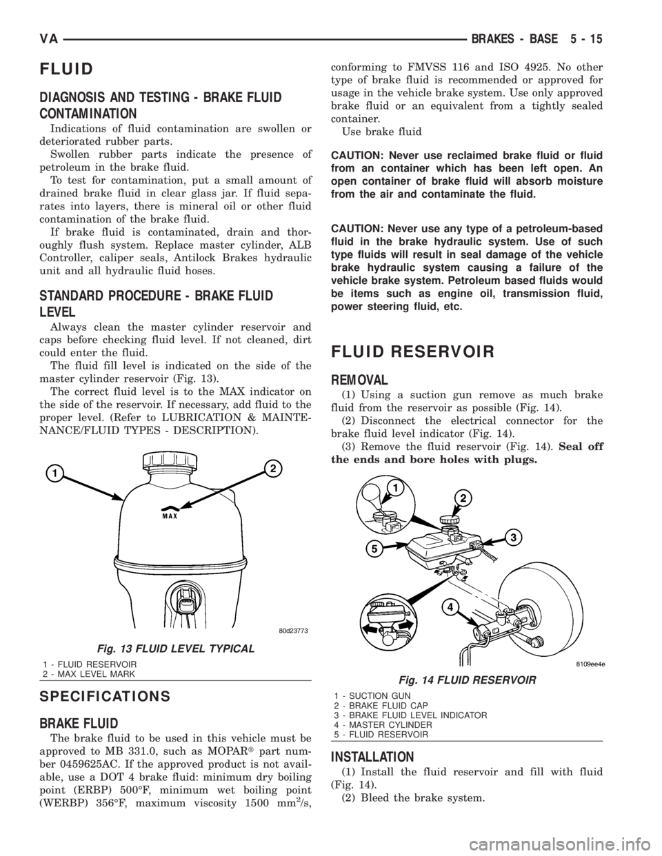
The fluid fill level is indicated on the side of the
master cylinder reservoir (Fig. 13).
The correct fluid level is to the MAX indicator on
the side of the reservoir. If necessary, add fluid to the
proper level. (Refer to LUBRICATION & MAINTE-
NANCE/FLUID TYPES - DESCRIPTION).
SPECIFICATIONS
BRAKE FLUID
The brake fluid to be used in this vehicle must be
approved to MB 331.0, such as MOPARtpart num-
ber 0459625AC. If the approved product is not avail-
able, use a DOT 4 brake fluid: minimum dry boiling
point (ERBP) 500ÉF, minimum wet boiling point
(WERBP) 356ÉF, maximum viscosity 1500 mm
2/s,conforming to FMVSS 116 and ISO 4925. No other
type of brake fluid is recommended or approved for
usage in the vehicle brake system. Use only approved
brake fluid or an equivalent from a tightly sealed
container.
Use brake fluid
CAUTION: Never use reclaimed brake fluid or fluid
from an container which has been left open. An
open container of brake fluid will absorb moisture
from the air and contaminate the fluid.
CAUTION: Never use any type of a petroleum-based
fluid in the brake hydraulic system. Use of such
type fluids will result in seal damage of the vehicle
brake hydraulic system causing a failure of the
vehicle brake system. Petroleum based fluids would
be items such as engine oil, transmission fluid,
power steering fluid, etc.
FLUID RESERVOIR
REMOVAL
(1) Using a suction gun remove as much brake
fluid from the reservoir as possible (Fig. 14).
(2) Disconnect the electrical connector for the
brake fluid level indicator (Fig. 14).
(3) Remove the fluid reservoir (Fig. 14).Seal off
the ends and bore holes with plugs.
INSTALLATION
(1) Install the fluid reservoir and fill with fluid
(Fig. 14).
(2) Bleed the brake system.
Fig. 13 FLUID LEVEL TYPICAL
1 - FLUID RESERVOIR
2 - MAX LEVEL MARK
Fig. 14 FLUID RESERVOIR
1 - SUCTION GUN
2 - BRAKE FLUID CAP
3 - BRAKE FLUID LEVEL INDICATOR
4 - MASTER CYLINDER
5 - FLUID RESERVOIR
VABRAKES - BASE 5 - 15
Page 819 of 2305
BRAKES - ABS
TABLE OF CONTENTS
page page
BRAKES - ABS
SPECIFICATIONS - TORQUE CHART........30
ELECTRICAL
DESCRIPTION.........................30
OPERATION...........................30
FRONT WHEEL SPEED SENSOR
REMOVAL.............................31
INSTALLATION.........................31
REAR WHEEL SPEED SENSOR
REMOVAL.............................31
INSTALLATION.........................32
TONE WHEEL
REMOVAL.............................32
INSTALLATION.........................32
STEERING ANGLE SENSOR
DESCRIPTION.........................32REMOVAL.............................33
INSTALLATION.........................33
LATERAL ACCELERATION SENSOR
DESCRIPTION.........................33
REMOVAL.............................33
INSTALLATION.........................34
YAW RATE SENSOR
DESCRIPTION.........................35
REMOVAL.............................35
INSTALLATION.........................36
HCU (HYDRAULIC CONTROL UNIT)
DESCRIPTION.........................36
REMOVAL.............................36
INSTALLATION.........................37
BRAKES - ABS
SPECIFICATIONS - TORQUE CHART
TORQUE SPECIFICATIONS
DESCRIPTION N´m Ft. Lbs. In. Lbs.
Brake Lines To Hydraulic
unit16 Ð 12
ELECTRICAL
DESCRIPTION
NOTE: Wheel speed sensor should be installed all
the way into the clamping bushings, the wheel
speed sensor will self adjust when the vehicle is
moved.
The ABS brake system uses 4 wheel speed sensors.
A sensor is mounted to each front hub/bearings in
the front. A rear sensor is mounted to each rear sup-
port plate.
OPERATION
The Wheel Speed Sensor consists of a magnet sur-
rounded by windings from a single strand of wire.
The sensor sends a small AC signal to the CAB. This
signal is generated by magnetic induction. The mag-netic induction is created when a toothed sensor ring
(exciter ring or tone wheel) passes the stationary
magnetic WSS.
When the ring gear is rotated, the exciter ring
passes the tip of the WSS. As the exciter ring tooth
approaches the tip of the WSS, the magnetic lines of
force expand, causing the magnetic field to cut across
the sensor's windings. This, in turn causes current to
flow through the WSS circuit (Fig. 1) in one direc-
tion. When the exciter ring tooth moves away from
the sensor tip, the magnetic lines of force collapse
cutting the winding in the opposite direction. This
causes the current to flow in the opposite direction.
Every time a tooth of the exciter ring passes the tip
of the WSS, an AC signal is generated. Each AC sig-
nal (positive to negative signal or sinewave) is inter-
preted by the CAB. It then compares the frequency of
the sinewave to a time value to calculate vehicle
speed. The CAB continues to monitor the frequency
5 - 30 BRAKES - ABSVA
Page 820 of 2305
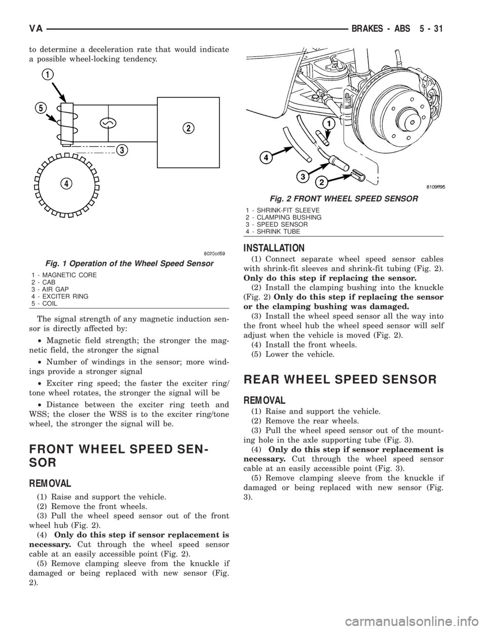
to determine a deceleration rate that would indicate
a possible wheel-locking tendency.
The signal strength of any magnetic induction sen-
sor is directly affected by:
²Magnetic field strength; the stronger the mag-
netic field, the stronger the signal
²Number of windings in the sensor; more wind-
ings provide a stronger signal
²Exciter ring speed; the faster the exciter ring/
tone wheel rotates, the stronger the signal will be
²Distance between the exciter ring teeth and
WSS; the closer the WSS is to the exciter ring/tone
wheel, the stronger the signal will be.
FRONT WHEEL SPEED SEN-
SOR
REMOVAL
(1) Raise and support the vehicle.
(2) Remove the front wheels.
(3) Pull the wheel speed sensor out of the front
wheel hub (Fig. 2).
(4)Only do this step if sensor replacement is
necessary.Cut through the wheel speed sensor
cable at an easily accessible point (Fig. 2).
(5) Remove clamping sleeve from the knuckle if
damaged or being replaced with new sensor (Fig.
2).
INSTALLATION
(1) Connect separate wheel speed sensor cables
with shrink-fit sleeves and shrink-fit tubing (Fig. 2).
Only do this step if replacing the sensor.
(2) Install the clamping bushing into the knuckle
(Fig. 2)Only do this step if replacing the sensor
or the clamping bushing was damaged.
(3) Install the wheel speed sensor all the way into
the front wheel hub the wheel speed sensor will self
adjust when the vehicle is moved (Fig. 2).
(4) Install the front wheels.
(5) Lower the vehicle.
REAR WHEEL SPEED SENSOR
REMOVAL
(1) Raise and support the vehicle.
(2) Remove the rear wheels.
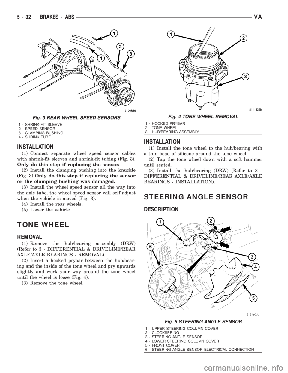
(3) Pull the wheel speed sensor out of the mount-
ing hole in the axle supporting tube (Fig. 3).
(4)Only do this step if sensor replacement is
necessary.Cut through the wheel speed sensor
cable at an easily accessible point (Fig. 3).
(5) Remove clamping sleeve from the knuckle if
damaged or being replaced with new sensor (Fig.
3).
Fig. 1 Operation of the Wheel Speed Sensor
1 - MAGNETIC CORE
2 - CAB
3 - AIR GAP
4 - EXCITER RING
5 - COIL
Fig. 2 FRONT WHEEL SPEED SENSOR
1 - SHRINK-FIT SLEEVE
2 - CLAMPING BUSHING
3 - SPEED SENSOR
4 - SHRINK TUBE
VABRAKES - ABS 5 - 31
Page 821 of 2305
INSTALLATION
(1) Connect separate wheel speed sensor cables
with shrink-fit sleeves and shrink-fit tubing (Fig. 3).
Only do this step if replacing the sensor.
(2) Install the clamping bushing into the knuckle
(Fig. 3)Only do this step if replacing the sensor
or the clamping bushing was damaged.
(3) Install the wheel speed sensor all the way into
the axle tube, the wheel speed sensor will self adjust
when the vehicle is moved (Fig. 3).
(4) Install the rear wheels.
(5) Lower the vehicle.
TONE WHEEL
REMOVAL
(1) Remove the hub/bearing assembly (DRW)
(Refer to 3 - DIFFERENTIAL & DRIVELINE/REAR
AXLE/AXLE BEARINGS - REMOVAL).
(2) Insert a hooked prybar between the hub/bear-
ing and the inside of the tone wheel and pry upwards
slightly and work your way around the tone wheel
until the wheel is loose (Fig. 4).
(3) Remove the tone wheel.
INSTALLATION
(1) Install the tone wheel to the hub/bearing with
a thin bead of silicone around the tone wheel.
(2) Tap the tone wheel down with a soft hammer
until seated.
(3) Install the hub/bearing (DRW) (Refer to 3 -
DIFFERENTIAL & DRIVELINE/REAR AXLE/AXLE
BEARINGS - INSTALLATION).
STEERING ANGLE SENSOR
DESCRIPTION
Fig. 3 REAR WHEEL SPEED SENSORS
1 - SHRINK-FIT SLEEVE
2 - SPEED SENSOR
3 - CLAMPING BUSHING
4 - SHRINK TUBE
Fig. 4 TONE WHEEL REMOVAL
1 - HOOKED PRYBAR
2 - TONE WHEEL
3 - HUB/BEARING ASSEMBLY
Fig. 5 STEERING ANGLE SENSOR
1 - UPPER STEERING COLUMN COVER
2 - CLOCKSPRING
3 - STEERING ANGLE SENSOR
4 - LOWER STEERING COLUMN COVER
5 - FRONT COVER
6 - STEERING ANGLE SENSOR ELECTRICAL CONNECTION
5 - 32 BRAKES - ABSVA
Page 822 of 2305
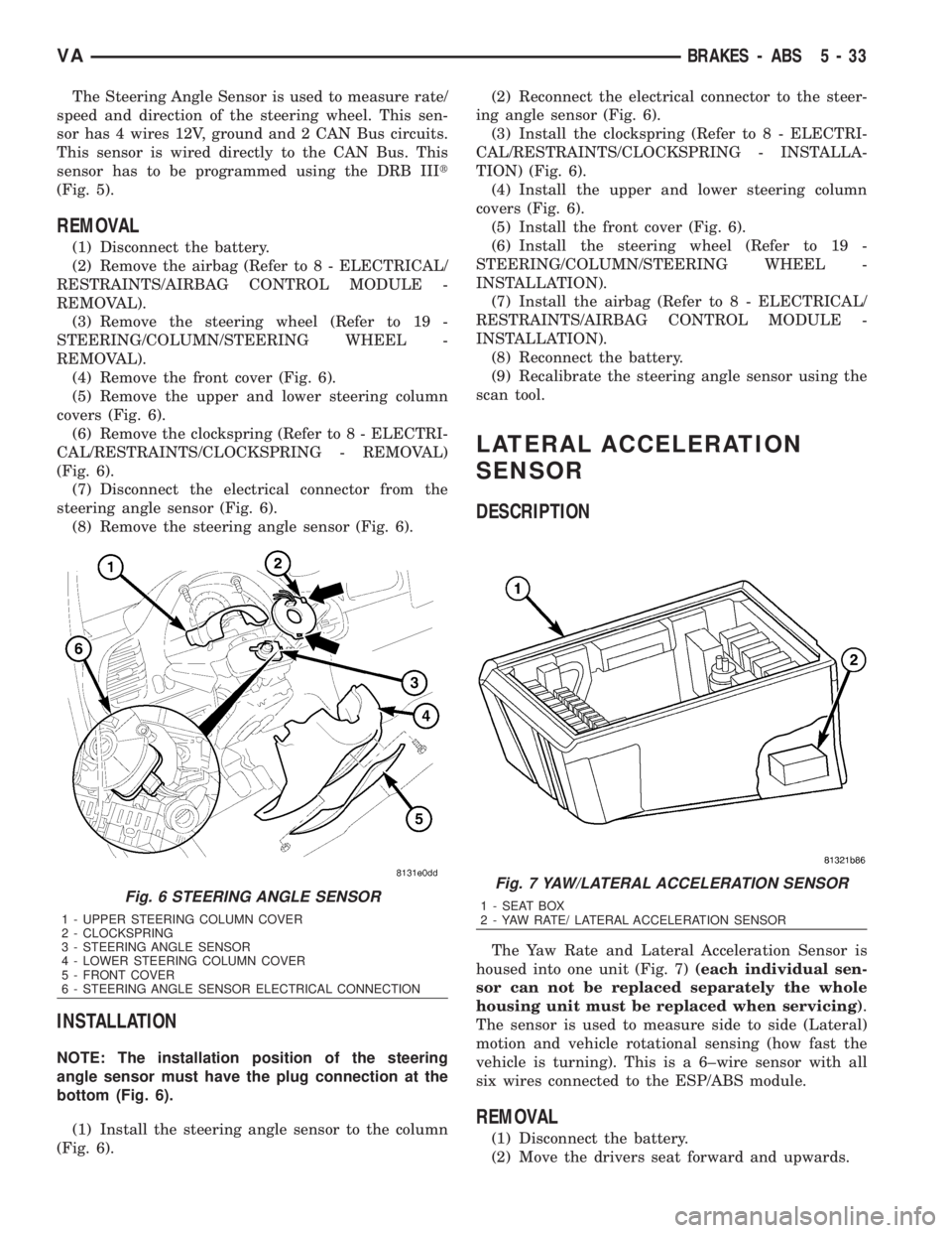
The Steering Angle Sensor is used to measure rate/
speed and direction of the steering wheel. This sen-
sor has 4 wires 12V, ground and 2 CAN Bus circuits.
This sensor is wired directly to the CAN Bus. This
sensor has to be programmed using the DRB IIIt
(Fig. 5).
REMOVAL
(1) Disconnect the battery.
(2) Remove the airbag (Refer to 8 - ELECTRICAL/
RESTRAINTS/AIRBAG CONTROL MODULE -
REMOVAL).
(3) Remove the steering wheel (Refer to 19 -
STEERING/COLUMN/STEERING WHEEL -
REMOVAL).
(4) Remove the front cover (Fig. 6).
(5) Remove the upper and lower steering column
covers (Fig. 6).
(6) Remove the clockspring (Refer to 8 - ELECTRI-
CAL/RESTRAINTS/CLOCKSPRING - REMOVAL)
(Fig. 6).
(7) Disconnect the electrical connector from the
steering angle sensor (Fig. 6).
(8) Remove the steering angle sensor (Fig. 6).
INSTALLATION
NOTE: The installation position of the steering
angle sensor must have the plug connection at the
bottom (Fig. 6).
(1) Install the steering angle sensor to the column
(Fig. 6).(2) Reconnect the electrical connector to the steer-
ing angle sensor (Fig. 6).
(3) Install the clockspring (Refer to 8 - ELECTRI-
CAL/RESTRAINTS/CLOCKSPRING - INSTALLA-
TION) (Fig. 6).
(4) Install the upper and lower steering column
covers (Fig. 6).
(5) Install the front cover (Fig. 6).
(6) Install the steering wheel (Refer to 19 -
STEERING/COLUMN/STEERING WHEEL -
INSTALLATION).
(7) Install the airbag (Refer to 8 - ELECTRICAL/
RESTRAINTS/AIRBAG CONTROL MODULE -
INSTALLATION).
(8) Reconnect the battery.
(9) Recalibrate the steering angle sensor using the
scan tool.
LATERAL ACCELERATION
SENSOR
DESCRIPTION
The Yaw Rate and Lateral Acceleration Sensor is
housed into one unit (Fig. 7)(each individual sen-
sor can not be replaced separately the whole
housing unit must be replaced when servicing).
The sensor is used to measure side to side (Lateral)
motion and vehicle rotational sensing (how fast the
vehicle is turning). This is a 6±wire sensor with all
six wires connected to the ESP/ABS module.
REMOVAL
(1) Disconnect the battery.
(2) Move the drivers seat forward and upwards.
Fig. 6 STEERING ANGLE SENSOR
1 - UPPER STEERING COLUMN COVER
2 - CLOCKSPRING
3 - STEERING ANGLE SENSOR
4 - LOWER STEERING COLUMN COVER
5 - FRONT COVER
6 - STEERING ANGLE SENSOR ELECTRICAL CONNECTION
Fig. 7 YAW/LATERAL ACCELERATION SENSOR
1 - SEAT BOX
2 - YAW RATE/ LATERAL ACCELERATION SENSOR
VABRAKES - ABS 5 - 33
Page 823 of 2305
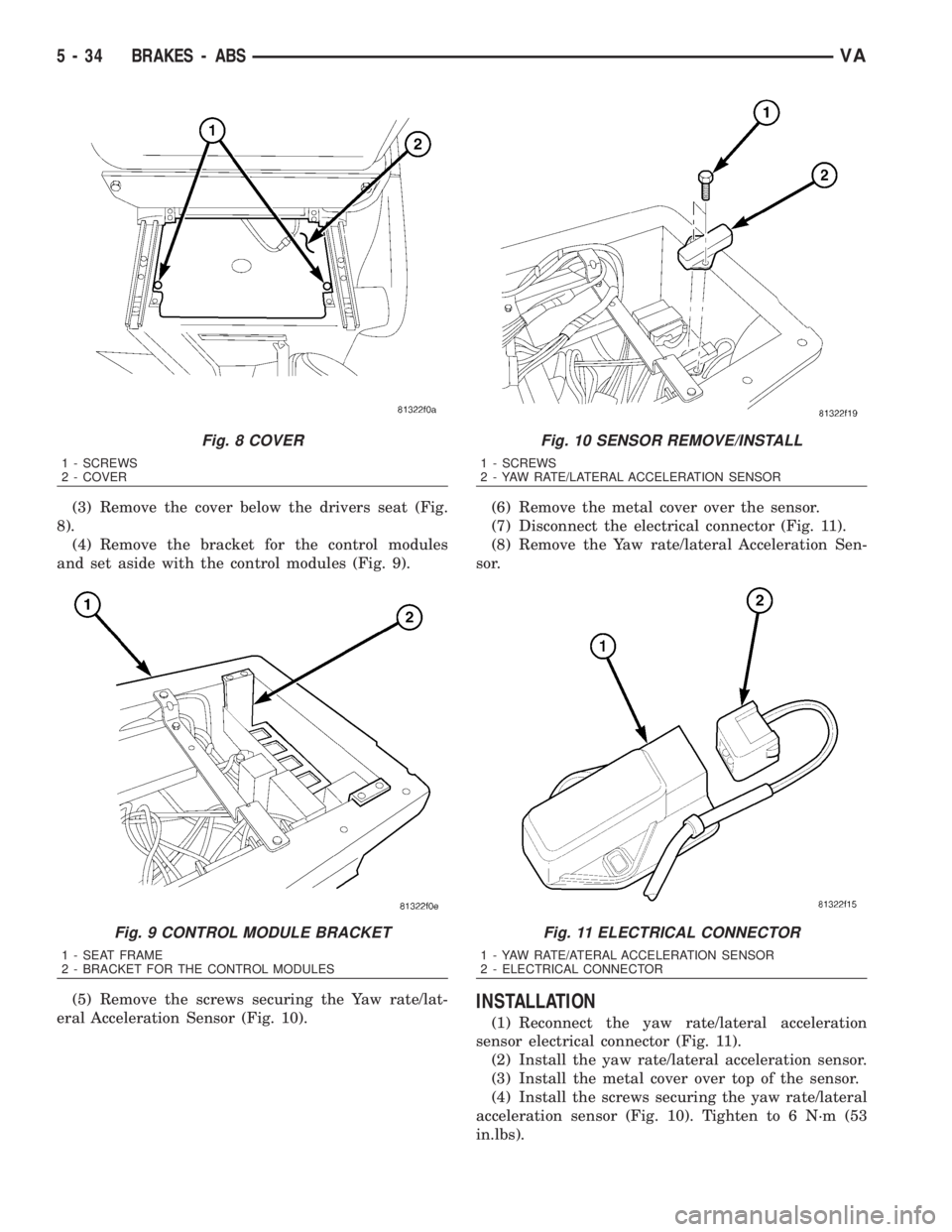
(3) Remove the cover below the drivers seat (Fig.
8).
(4) Remove the bracket for the control modules
and set aside with the control modules (Fig. 9).
(5) Remove the screws securing the Yaw rate/lat-
eral Acceleration Sensor (Fig. 10).(6) Remove the metal cover over the sensor.
(7) Disconnect the electrical connector (Fig. 11).
(8) Remove the Yaw rate/lateral Acceleration Sen-
sor.
INSTALLATION
(1) Reconnect the yaw rate/lateral acceleration
sensor electrical connector (Fig. 11).
(2) Install the yaw rate/lateral acceleration sensor.
(3) Install the metal cover over top of the sensor.
(4) Install the screws securing the yaw rate/lateral
acceleration sensor (Fig. 10). Tighten to 6 N´m (53
in.lbs).
Fig. 8 COVER
1 - SCREWS
2 - COVER
Fig. 9 CONTROL MODULE BRACKET
1 - SEAT FRAME
2 - BRACKET FOR THE CONTROL MODULES
Fig. 10 SENSOR REMOVE/INSTALL
1 - SCREWS
2 - YAW RATE/LATERAL ACCELERATION SENSOR
Fig. 11 ELECTRICAL CONNECTOR
1 - YAW RATE/ATERAL ACCELERATION SENSOR
2 - ELECTRICAL CONNECTOR
5 - 34 BRAKES - ABSVA
Page 824 of 2305
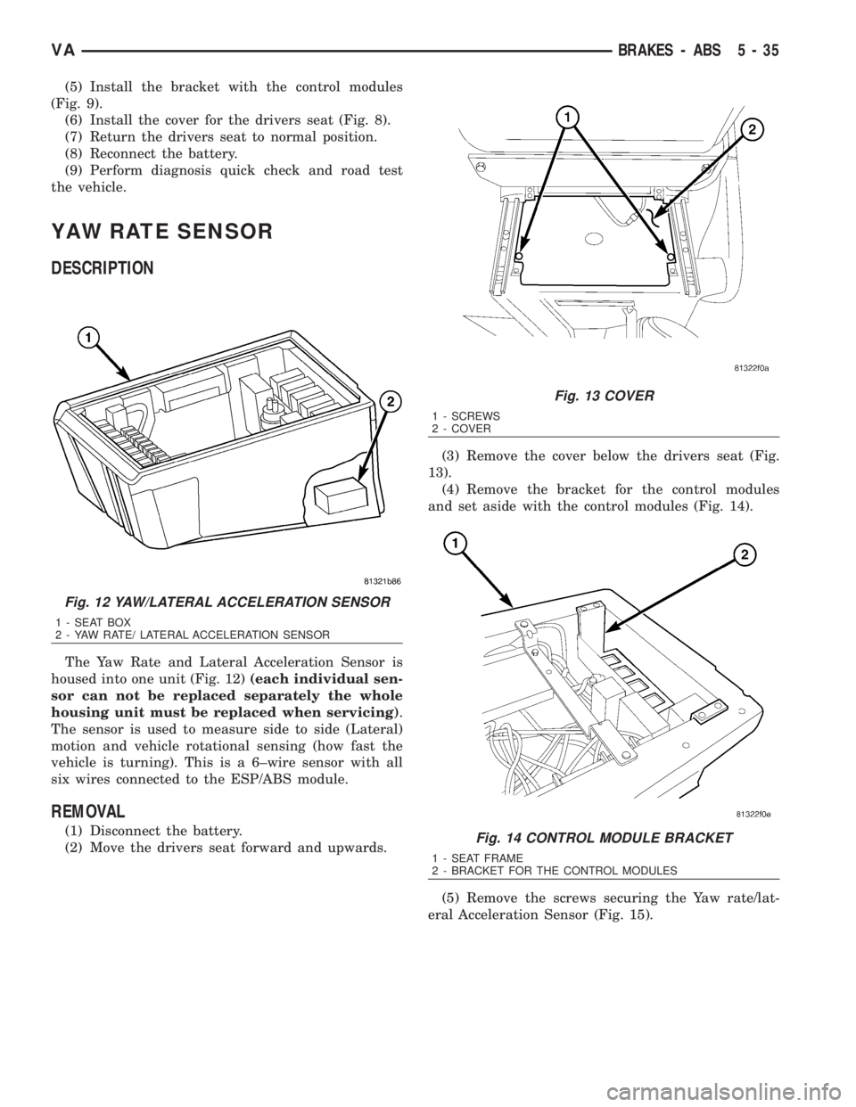
(5) Install the bracket with the control modules
(Fig. 9).
(6) Install the cover for the drivers seat (Fig. 8).
(7) Return the drivers seat to normal position.
(8) Reconnect the battery.
(9) Perform diagnosis quick check and road test
the vehicle.
YAW RATE SENSOR
DESCRIPTION
The Yaw Rate and Lateral Acceleration Sensor is
housed into one unit (Fig. 12)(each individual sen-
sor can not be replaced separately the whole
housing unit must be replaced when servicing).
The sensor is used to measure side to side (Lateral)
motion and vehicle rotational sensing (how fast the
vehicle is turning). This is a 6±wire sensor with all
six wires connected to the ESP/ABS module.
REMOVAL
(1) Disconnect the battery.
(2) Move the drivers seat forward and upwards.(3) Remove the cover below the drivers seat (Fig.
13).
(4) Remove the bracket for the control modules
and set aside with the control modules (Fig. 14).
(5) Remove the screws securing the Yaw rate/lat-
eral Acceleration Sensor (Fig. 15).
Fig. 12 YAW/LATERAL ACCELERATION SENSOR
1 - SEAT BOX
2 - YAW RATE/ LATERAL ACCELERATION SENSOR
Fig. 13 COVER
1 - SCREWS
2 - COVER
Fig. 14 CONTROL MODULE BRACKET
1 - SEAT FRAME
2 - BRACKET FOR THE CONTROL MODULES
VABRAKES - ABS 5 - 35