power steering MERCEDES-BENZ SPRINTER 2006 User Guide
[x] Cancel search | Manufacturer: MERCEDES-BENZ, Model Year: 2006, Model line: SPRINTER, Model: MERCEDES-BENZ SPRINTER 2006Pages: 2305, PDF Size: 48.12 MB
Page 791 of 2305
POWER BRAKE BOOSTER
DESCRIPTION.........................19
OPERATION...........................19
REMOVAL.............................20
INSTALLATION.........................20
ROTORS
REMOVAL
REMOVAL - FRONT (SRW)..............20
REMOVAL - REAR (SRW)...............20
REMOVAL - FRONT (DRW)..............21
REMOVAL - REAR (DRW)...............21
INSTALLATION
INSTALLATION - FRONT (SRW)..........22
INSTALLATION - REAR (SRW)...........22
INSTALLATION - FRONT (DRW)..........22
INSTALLATION - REAR (DRW)...........22
SUPPORT PLATE
REMOVAL - REAR......................23
INSTALLATION - REAR...................23
PARKING BRAKE
SPECIFICATIONS
TORQUE CHART......................23
SPECIAL TOOLS
PARK BRAKE........................24
CABLE TENSIONER
REMOVAL.............................24INSTALLATION.........................24
CABLES
REMOVAL
REMOVAL - FRONT....................24
REMOVAL - REAR.....................25
INSTALLATION
INSTALLATION - FRONT................25
INSTALLATION - REAR.................26
ADJUSTMENTS
ADJUSTMENT - PARKING BRAKE CABLES . 26
LEVER
REMOVAL.............................26
INSTALLATION.........................27
SHOES
REMOVAL
REMOVAL - (SRW)....................27
REMOVAL - (DRW)....................27
CLEANING - REAR DRUM IN HAT BRAKE....28
INSTALLATION
INSTALLATION - (SRW).................28
INSTALLATION - (DRW).................28
ADJUSTMENTS
ADJUSTMENT........................28
BRAKES - BASE
DIAGNOSIS AND TESTING - BASE BRAKE SYS-
TEM
Base brake components consist of the brake pads,
calipers, brake drum in hat rotor in the rear, rotors,
brake lines, master cylinder, booster, and parking
brake components.
Brake diagnosis involves determining if the prob-
lem is related to a mechanical, hydraulic, or vacuum
operated component.
The first diagnosis step is the preliminary check.
PRELIMINARY BRAKE CHECK
(1) Check condition of tires and wheels. Damaged
wheels and worn, damaged, or underinflated tires
can cause pull, shudder, vibration, and a condition
similar to grab.
(2) If complaint was based on noise when braking,
check suspension components. Jounce front and rear
of vehicle and listen for noise that might be caused
by loose, worn or damaged suspension or steering
components.
(3) Inspect brake fluid level and condition. Note
that the brake reservoir fluid level will decrease in
proportion to normal lining wear.Also note that
brake fluid tends to darken over time. This is
normal and should not be mistaken for contam-
ination.(a) If fluid level is abnormally low, look for evi-
dence of leaks at calipers, wheel cylinders, brake
lines, and master cylinder.
(b) If fluid appears contaminated, drain out a
sample to examine. System will have to be flushed
if fluid is separated into layers, or contains a sub-
stance other than brake fluid. The system seals
and cups will also have to be replaced after flush-
ing. Use clean brake fluid to flush the system.
(4) Check parking brake operation. Verify free
movement and full release of cables and pedal. Also
note if vehicle was being operated with parking
brake partially applied.
(5) Check brake pedal operation. Verify that pedal
does not bind and has adequate free play. If pedal
lacks free play, check pedal and power booster for
being loose or for bind condition. Do not road test
until condition is corrected.
(6) Check booster vacuum check valve and hose.
(7) If components checked appear OK, road test
the vehicle.
ROAD TESTING
(1) If complaint involved low brake pedal, pump
pedal and note if it comes back up to normal height.
(2) Check brake pedal response with transmission
in Neutral and engine running. Pedal should remain
firm under constant foot pressure.
5 - 2 BRAKES - BASEVA
Page 804 of 2305
FLUID
DIAGNOSIS AND TESTING - BRAKE FLUID
CONTAMINATION
Indications of fluid contamination are swollen or
deteriorated rubber parts.
Swollen rubber parts indicate the presence of
petroleum in the brake fluid.
To test for contamination, put a small amount of
drained brake fluid in clear glass jar. If fluid sepa-
rates into layers, there is mineral oil or other fluid
contamination of the brake fluid.
If brake fluid is contaminated, drain and thor-
oughly flush system. Replace master cylinder, ALB
Controller, caliper seals, Antilock Brakes hydraulic
unit and all hydraulic fluid hoses.
STANDARD PROCEDURE - BRAKE FLUID
LEVEL
Always clean the master cylinder reservoir and
caps before checking fluid level. If not cleaned, dirt
could enter the fluid.
The fluid fill level is indicated on the side of the
master cylinder reservoir (Fig. 13).
The correct fluid level is to the MAX indicator on
the side of the reservoir. If necessary, add fluid to the
proper level. (Refer to LUBRICATION & MAINTE-
NANCE/FLUID TYPES - DESCRIPTION).
SPECIFICATIONS
BRAKE FLUID
The brake fluid to be used in this vehicle must be
approved to MB 331.0, such as MOPARtpart num-
ber 0459625AC. If the approved product is not avail-
able, use a DOT 4 brake fluid: minimum dry boiling
point (ERBP) 500ÉF, minimum wet boiling point
(WERBP) 356ÉF, maximum viscosity 1500 mm
2/s,conforming to FMVSS 116 and ISO 4925. No other
type of brake fluid is recommended or approved for
usage in the vehicle brake system. Use only approved
brake fluid or an equivalent from a tightly sealed
container.
Use brake fluid
CAUTION: Never use reclaimed brake fluid or fluid
from an container which has been left open. An
open container of brake fluid will absorb moisture
from the air and contaminate the fluid.
CAUTION: Never use any type of a petroleum-based
fluid in the brake hydraulic system. Use of such
type fluids will result in seal damage of the vehicle
brake hydraulic system causing a failure of the
vehicle brake system. Petroleum based fluids would
be items such as engine oil, transmission fluid,
power steering fluid, etc.
FLUID RESERVOIR
REMOVAL
(1) Using a suction gun remove as much brake
fluid from the reservoir as possible (Fig. 14).
(2) Disconnect the electrical connector for the
brake fluid level indicator (Fig. 14).
(3) Remove the fluid reservoir (Fig. 14).Seal off
the ends and bore holes with plugs.
INSTALLATION
(1) Install the fluid reservoir and fill with fluid
(Fig. 14).
(2) Bleed the brake system.
Fig. 13 FLUID LEVEL TYPICAL
1 - FLUID RESERVOIR
2 - MAX LEVEL MARK
Fig. 14 FLUID RESERVOIR
1 - SUCTION GUN
2 - BRAKE FLUID CAP
3 - BRAKE FLUID LEVEL INDICATOR
4 - MASTER CYLINDER
5 - FLUID RESERVOIR
VABRAKES - BASE 5 - 15
Page 832 of 2305
ACCESSORY DRIVE
TABLE OF CONTENTS
page page
BELT TENSIONERS
DESCRIPTION..........................5
OPERATION............................5
DRIVE BELTS
DIAGNOSIS AND TESTING - ACCESSORY
DRIVE BELT..........................5REMOVAL
REMOVAL............................8
REMOVAL............................8
INSTALLATION
INSTALLATION........................8
INSTALLATION........................8
BELT TENSIONERS
DESCRIPTION
CAUTION: Do not attempt to check belt tension with
a belt tension gauge on vehicles equipped with an
automatic belt tensioner.
Drive belts on all engines are equipped with a
spring loaded automatic belt tensioner. This ten-
sioner maintains constant belt tension at all times
and requires no maintenance or adjustment. (Fig. 1)
OPERATION
WARNING: The automatic belt tensioner assembly
is spring loaded. do not attempt to disassemble the
tensioner assembly.
The automatic belt tensioner maintains correct belt
tension using a coiled spring within the tensioner
housing. The spring applies pressure to the tensionerarm pressing the arm into the belt, tensioning the
belt.
If a new belt is being installed, the arrow must be
within approximately 3 mm (1/8 in.) of indexing
mark. Belt is considered new if it has been used 15
minutes or less. If this specification cannot be met,
check for:
²The wrong belt being installed (incorrect length/
width)
²Worn bearings on an engine accessory (A/C com-
pressor, power steering pump, water pump, idler pul-
ley or generator)
²A pulley on an engine accessory being loose
²Misalignment of an engine accessory
²Belt incorrectly routed.
DRIVE BELTS
DIAGNOSIS AND TESTING - ACCESSORY
DRIVE BELT
VISUAL DIAGNOSIS
When diagnosing serpentine accessory drive belts,
small cracks that run across the ribbed surface of the
belt from rib to rib (Fig. 2), are considered normal.
These are not a reason to replace the belt. However,
cracks running along a rib (not across) arenotnor-
mal. Any belt with cracks running along a rib must
be replaced (Fig. 2). Also replace the belt if it has
excessive wear, frayed cords or severe glazing.
Refer to ACCESSORY DRIVE BELT DIAGNOSIS
CHART for further belt diagnosis.
Fig. 1 Accessory Drive Belt
1 - WATER PUMP
2 - ACCESSORY DRIVE BELT
3 - AUTOMATIC BELT TENSIONER
4 - 3/89SQUARE BOLT
5 - MOUNT. BOLT
VAACCESSORY DRIVE 7 - 5
Page 835 of 2305
REMOVAL
REMOVAL
CAUTION: Do not attempt to check belt tension with
a belt tension gauge on vehicles equipped with an
automatic belt tensioner.
NOTE: The belt routing schematics are published
from the latest information available at the time of
publication. If anything differs between these sche-
matics and the Belt Routing Label, use the sche-
matics on Belt Routing Label.This label is located in
the engine compartment.
(1) Remove A/C compressor drive belt (Refer to 7 -
COOLING/ACCESSORY DRIVE/DRIVE BELTS -
REMOVAL).
(2) A 3/8 inch square hole is provided in the auto-
matic belt tensioner. Attach a 3/8 inch drive-long
handle ratchet to this hole (Fig. 3).
(3) Rotate ratchet and tensioner assembly counter-
clockwise (as viewed from front) until tension has
been relieved from belt (Fig. 3).
(4) Remove belt from water pump pulley first.
(5) Remove belt from vehicle.
REMOVAL
(1) Loosen tension adjuster.
(2) Remove A/C compressor drive belt.
INSTALLATION
INSTALLATION
CAUTION: When installing the accessory drive belt,
the belt must be the correct length and routed cor-
rectly. If not, engine may overheat due to water
pump rotating in wrong direction.
(1) Position drive belt over all pulleysexcept
water pump pulley (Fig. 4).
(2) Attach a 3/8 inch ratchet to tensioner.
(3) Rotate ratchet and belt tensioner counterclock-
wise. Place belt over water pump pulley. Let ten-
sioner rotate back into place. Remove ratchet. Be
sure belt is properly seated on all pulleys.
(4) Install A/C compressor drive belt (Refer to 7 -
COOLING/ACCESSORY DRIVE/DRIVE BELTS -
INSTALLATION).
INSTALLATION
(1) Position A/C compressor drive belt over crank-
shaft pulley and A/C compressor pulley.
(2) Tighten drive belt tensioner.
Fig. 3 DRIVE BELT TENSIONER
1 - ACCESSORY DRIVE BELT TENSIONER
2 - RATCHET WRENCH
Fig. 4 ACCESSORY DRIVE BELT ROUTING
1 - A/C COMPRESSOR
2 - POWER STEERING
3 - DRIVE BELT TENSIONER
4 - CRANKSHAFT PULLEY
5 - WATER PUMP PULLEY
6 - GENERATOR
7 - IDLER PULLEY
7 - 8 ACCESSORY DRIVEVA
Page 845 of 2305
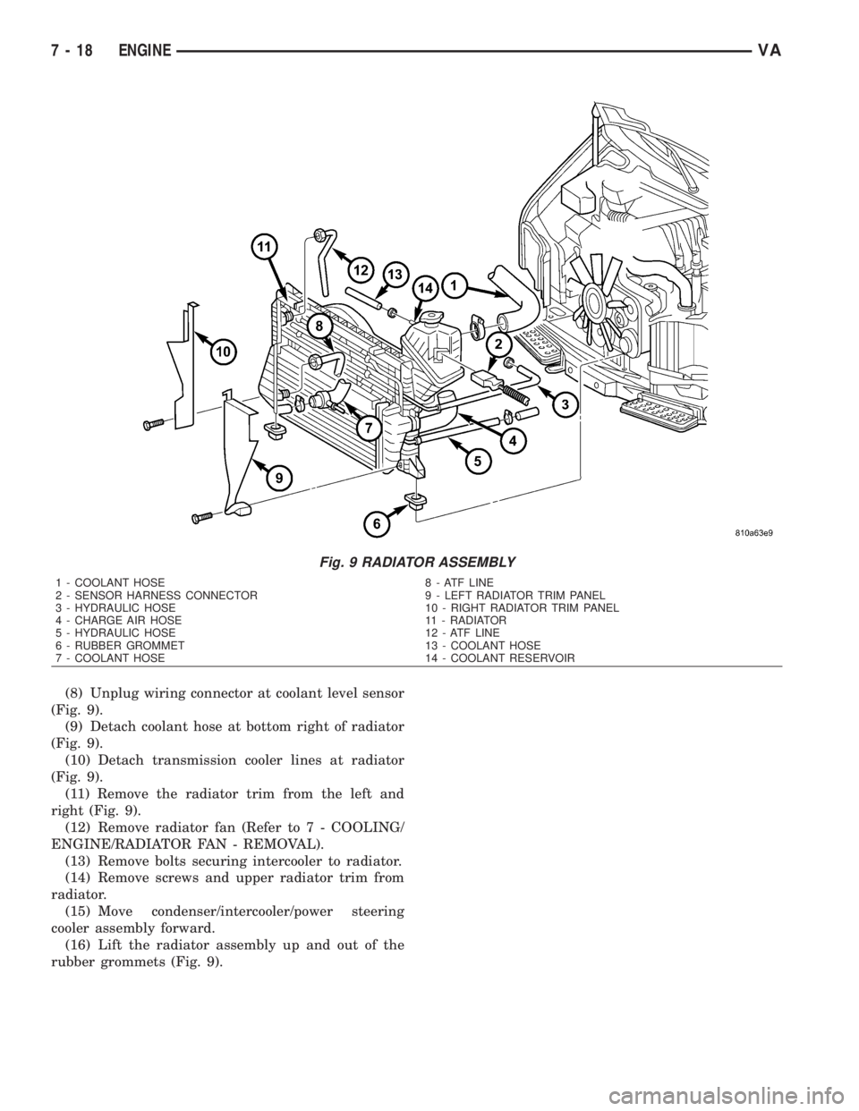
(8) Unplug wiring connector at coolant level sensor
(Fig. 9).
(9) Detach coolant hose at bottom right of radiator
(Fig. 9).
(10) Detach transmission cooler lines at radiator
(Fig. 9).
(11) Remove the radiator trim from the left and
right (Fig. 9).
(12) Remove radiator fan (Refer to 7 - COOLING/
ENGINE/RADIATOR FAN - REMOVAL).
(13) Remove bolts securing intercooler to radiator.
(14) Remove screws and upper radiator trim from
radiator.
(15) Move condenser/intercooler/power steering
cooler assembly forward.
(16) Lift the radiator assembly up and out of the
rubber grommets (Fig. 9).
Fig. 9 RADIATOR ASSEMBLY
1 - COOLANT HOSE 8 - ATF LINE
2 - SENSOR HARNESS CONNECTOR 9 - LEFT RADIATOR TRIM PANEL
3 - HYDRAULIC HOSE 10 - RIGHT RADIATOR TRIM PANEL
4 - CHARGE AIR HOSE 11 - RADIATOR
5 - HYDRAULIC HOSE 12 - ATF LINE
6 - RUBBER GROMMET 13 - COOLANT HOSE
7 - COOLANT HOSE 14 - COOLANT RESERVOIR
7 - 18 ENGINEVA
Page 846 of 2305
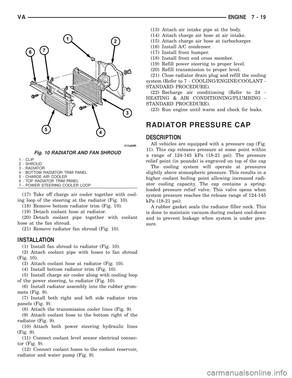
(17) Take off charge air cooler together with cool-
ing loop of the steering at the radiator (Fig. 10).
(18) Remove bottom radiator trim (Fig. 10).
(19) Detach coolant hose at radiator.
(20) Detach coolant pipe together with coolant
hose at the fan shroud.
(21) Remove radiator fan shroud (Fig. 10).
INSTALLATION
(1) Install fan shroud to radiator (Fig. 10).
(2) Attach coolant pipe with hoses to fan shroud
(Fig. 10).
(3) Attach coolant hose at radiator (Fig. 10).
(4) Install bottom radiator trim (Fig. 10).
(5) Install charge air cooler along with cooling loop
of the power steering, to radiator (Fig. 10).
(6) Install radiator assembly into the rubber grom-
mets (Fig. 9).
(7) Install both right and left side radiator trim
panels (Fig. 9).
(8) Attach the transmission cooler lines (Fig. 9).
(9) Attach coolant hose to the bottom right of the
radiator (Fig. 9).
(10) Attach both power steering hydraulic lines
(Fig. 9).
(11) Connect coolant level sensor electrical connec-
tor (Fig. 9).
(12) Connect coolant hoses to the coolant reservoir,
radiator and water pump (Fig. 9).(13) Attach air intake pipe at the body.
(14) Attach charge air hose at air intake.
(15) Attach charge air hose at turbocharger.
(16) Install A/C condenser.
(17) Install front bumper.
(18) Install front end cross member.
(19) Refill power steering to proper level.
(20) Refill transmission to proper level.
(21) Close radiator drain plug and refill the cooling
system (Refer to 7 - COOLING/ENGINE/COOLANT -
STANDARD PROCEDURE).
(22) Recharge air conditioning (Refer to 24 -
HEATING & AIR CONDITIONING/PLUMBING -
STANDARD PROCEDURE).
(23) Run engine until warm and check for leaks.
RADIATOR PRESSURE CAP
DESCRIPTION
All vehicles are equipped with a pressure cap (Fig.
11). This cap releases pressure at some point within
a range of 124-145 kPa (18-21 psi). The pressure
relief point (in pounds) is engraved on top of the cap
The cooling system will operate at pressures
slightly above atmospheric pressure. This results in a
higher coolant boiling point allowing increased radi-
ator cooling capacity. The cap contains a spring-
loaded pressure relief valve. This valve opens when
system pressure reaches the release range of 124-145
kPa (18-21 psi).
A rubber gasket seals the radiator filler neck. This
is done to maintain vacuum during coolant cool-down
and to prevent leakage when system is under pres-
sure.
Fig. 10 RADIATOR AND FAN SHROUD
1 - CLIP
2 - SHROUD
3 - RADIATOR
4 - BOTTOM RADIATOR TRIM PANEL
5 - CHARGE AIR COOLER
6 - TOP RADIATOR TRIM PANEL
7 - POWER STEERING COOLER LOOP
VAENGINE 7 - 19
Page 895 of 2305
Starting System Diagnosis
CONDITION POSSIBLE CAUSE CORRECTION
STARTER DOES NOT
DISENGAGE.1. Starter motor improp-
erly installed.1. Refer to Starter Motor Removal and Installation.
Tighten starter mounting hardware to correct torque
specifications.
2. Starter relay faulty. 2. Refer to Starter Relay Diagnosis and Testing. Re-
place starter relay if required.
3. Ignition switch faulty. 3. Refer to Ignition Switch and Key Lock Cylinder. Re-
place ignition switch if required.
4. Starter motor faulty. 4. If all other starting system components and circuits
test OK, replace starter motor.
INSPECTION
For complete starter wiring circuit diagrams, refer
to 8, Wiring Diagrams. Before removing any unit
from starting system for repair or diagnosis, perform
the following inspections:
WARNING: ON VEHICLES EQUIPPED WITH AIR-
BAGS, REFER TO 8, PASSIVE RESTRAINT SYS-
TEMS, BEFORE ATTEMPTING ANY STEERING
WHEEL, STEERING COLUMN, OR INSTRUMENT
PANEL COMPONENT DIAGNOSIS OR SERVICE.
FAILURE TO TAKE THE PROPER PRECAUTIONS
COULD RESULT IN ACCIDENTAL AIRBAG DEPLOY-
MENT AND POSSIBLE PERSONAL INJURY.
²Battery- Visually inspect battery for indica-
tions of physical damage and loose or corroded cable
connections. Determine state-of-charge and cranking
capacity of battery. Charge or replace battery if
required. Refer toBatteryin 8, Battery.
²Ignition Switch- Visually inspect ignition
switch for indications of physical damage and loose
or corroded wire harness connections. Refer toIgni-
tion Switch and Key Lock Cylinder.
²Park/Neutral Position Switch- Visually
inspect park/neutral position switch for indications of
physical damage and loose or corroded wire harness
connections. Refer toPark/Neutral Position
Switchin 21, Transmission.
²Starter Relay- Visually inspect starter relay
for indications of physical damage and loose or cor-
roded wire harness connections.
²Starter Motor- Visually inspect starter motor
for indications of physical damage and loose or cor-
roded wire harness connections.
²Starter Solenoid- Visually inspect starter sole-
noid for indications of physical damage and loose or
corroded wire harness connections.
²Wiring- Visually inspect wire harnesses for
damage or corrosion. Repair or replace any faulty
wiring, as required. Refer to 8, Wiring Diagrams.
TESTING
COLD CRANKING TEST
For complete starter wiring circuit diagrams, refer
to 8, Wiring Diagrams. The battery must be fully-
charged and load-tested before proceeding. Refer to
Batteryin 8, Battery.
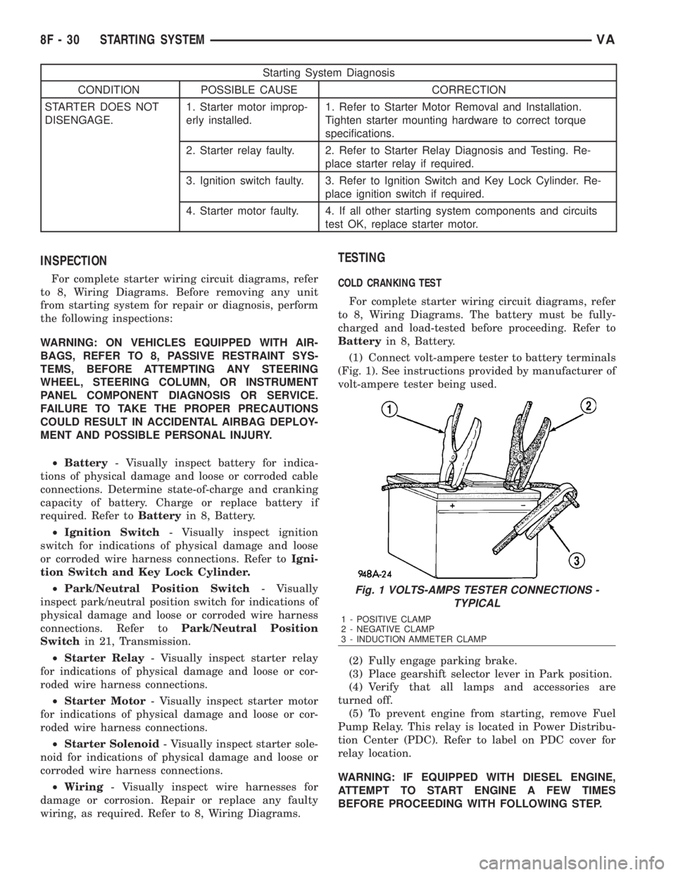
(1) Connect volt-ampere tester to battery terminals
(Fig. 1). See instructions provided by manufacturer of
volt-ampere tester being used.
(2) Fully engage parking brake.
(3) Place gearshift selector lever in Park position.
(4) Verify that all lamps and accessories are
turned off.
(5) To prevent engine from starting, remove Fuel
Pump Relay. This relay is located in Power Distribu-
tion Center (PDC). Refer to label on PDC cover for
relay location.
WARNING: IF EQUIPPED WITH DIESEL ENGINE,
ATTEMPT TO START ENGINE A FEW TIMES
BEFORE PROCEEDING WITH FOLLOWING STEP.
Fig. 1 VOLTS-AMPS TESTER CONNECTIONS -
TYPICAL
1 - POSITIVE CLAMP
2 - NEGATIVE CLAMP
3 - INDUCTION AMMETER CLAMP
8F - 30 STARTING SYSTEMVA
Page 952 of 2305
electrical package have a heavy duty 7-way trailer
tow connector installed in a bracket on the trailer
hitch receiver. This package includes a 7-way to
4-way connector adapter unit.
²Trailer Tow Control Module- Vehicles
equipped with a factory-approved, field-installed
trailer towing electrical package have a trailer tow
brake/turn control module located within the driver
side front seat riser that controls the brake lamp and
turn signal lamp outputs to the trailer lighting cir-
cuits.
²Turn Signal Relay- A turn signal relay is
installed in the fuse block located on the underside of
the steering column behind a fuse access panel in the
steering column opening cover on the instrument
panel. The electronic circuitry of the wipers, turn sig-
nals and engine start control module within the fuse
block controls the turn signal relay.
²Wipers, Turn Signals, Engine Start Control
Module- The wipers, turn signals and engine start
control module is integral to the fuse block located on
the underside of the steering column behind a fuse
access panel in the steering column opening cover on
the instrument panel. This module includes active
electronic elements that control the operation of the
turn signal relay based upon inputs from the multi-
function switch and feedback from the turn signal
circuits. (Refer to 8 - ELECTRICAL/POWER DISTRI-
BUTION/FUSE BLOCK - DESCRIPTION).
Hard wired circuitry connects the exterior lighting
system components to the electrical system of the
vehicle. These hard wired circuits are integral to sev-
eral wire harnesses, which are routed throughout the
vehicle and retained by many different methods.
These circuits may be connected to each other, to the
vehicle electrical system and to the exterior lighting
system components through the use of a combination
of soldered splices, splice block connectors, and many
different types of wire harness terminal connectors
and insulators. Refer to the appropriate wiring infor-
mation. The wiring information includes wiring dia-
grams, proper wire and connector repair procedures,
further details on wire harness routing and reten-
tion, as well as pin-out and location views for the
various wire harness connectors, splices and grounds.
OPERATION
Following are paragraphs that briefly describe the
operation of each of the major exterior lighting sys-
tems. The hard wired circuits and components of the
exterior lighting systems may be diagnosed and
tested using conventional diagnostic tools and proce-
dures. However, conventional diagnostic methods
may not prove conclusive in the diagnosis of the wip-
ers, turn signals and engine start control module
located within the fuse block underneath the steering
column, the ElectroMechanical Instrument Cluster
(EMIC), the Engine Control Module (ECM), or theController Area Network (CAN) data bus network.
The most reliable, efficient, and accurate means to
diagnose the electronic module within the fuse block,
the EMIC, the ECM, and the CAN data bus network
inputs and outputs related to the various exterior
lighting systems requires the use of a diagnostic scan
tool. Refer to the appropriate diagnostic information.
BACKUP LAMPS
The backup (or reverse) lamps have a path to
ground received at all times through the vehicle wire
harness from a ground point located on the frame
near the left end of the tailgate sill. The backup
lamps receive battery current on the backup lamp
supply circuit only when the backup lamp switch cir-
cuit of the Transmission Range Sensor (TRS) integral
to the gear shifter assembly is closed by the gear
shifter mechanism.
BRAKE LAMPS
The brake (or stop) lamps have a path to ground at
all times through the vehicle wire harness from a
ground point located on the frame near the left end
of the tailgate sill. The Center High Mounted Stop
Lamp (CHMSL) has a path to ground at all times
through the vehicle wire harness from a ground point
on the left side of the dash panel. The brake lamps
and CHMSL receive battery current on the brake
lamp switch output circuit when the brake lamp
switch is closed by the brake pedal arm.
DAYTIME RUNNING LAMPS
Vehicles manufactured for sale in Canada illumi-
nate the low beam headlamp bulb when the engine is
running and the exterior lamps are turned off. This
feature is enabled by the right and left Daytime Run-
ning Lamps (DRL) relays. When the DRL relays are
de-energized, they provide fused battery current from
the circuit K26 relay to the headlamp low beams.
When the headlamps are turned On using the left
(lighting) control stalk of the multi-function switch
the DRL relays are energized, which returns control
of the headlamps to the headlamp switch circuitry of
the multi-function switch. The circuit K26 relay is
energized by the ElectroMechanical Instrument Clus-
ter (EMIC) whenever it receives an electronic mes-
sage from the Engine Control Module (ECM) over the
Controller Area Network (CAN) data bus indicating
that the engine is running. The DRL and circuit K26
relays are installed in a relay bracket located below
the forward edge of the driver side front seat cushion
within the driver side front seat riser.
FRONT FOG LAMPS
Vehicles equipped with optional front fog lamps
have a front fog lamp relay installed in a relay
bracket located below the forward edge of the driver
side front seat cushion within the driver side front
VALAMPS/LIGHTING - EXTERIOR 8L - 3
Page 970 of 2305
MULTI - FUNCTION SWITCH
REMOVAL
WARNING: To avoid personal injury or death, on
vehicles equipped with airbags, disable the supple-
mental restraint system before attempting any
steering wheel, steering column, airbag, seat belt
tensioner, or instrument panel component diagno-
sis or service. Disconnect and isolate the battery
negative (ground) cable, then wait two minutes for
the system capacitor to discharge before perform-
ing further diagnosis or service. This is the only
sure way to disable the supplemental restraint sys-
tem. Failure to take the proper precautions could
result in accidental airbag deployment.
(1) Disconnect and isolate the battery negative
cable.
(2) Remove the fuse block from the underside of
the steering column. (Refer to 8 - ELECTRICAL/
POWER DISTRIBUTION/FUSE BLOCK -
REMOVAL).
(3) Remove the clockspring from the steering col-
umn. (Refer to 8 - ELECTRICAL/RESTRAINTS/
CLOCKSPRING - REMOVAL).
(4) If the vehicle is so equipped, remove the steer-
ing angle sensor from the steering column. (Refer to
5 - BRAKES/ELECTRICAL/STEERING ANGLE
SENSOR - REMOVAL).
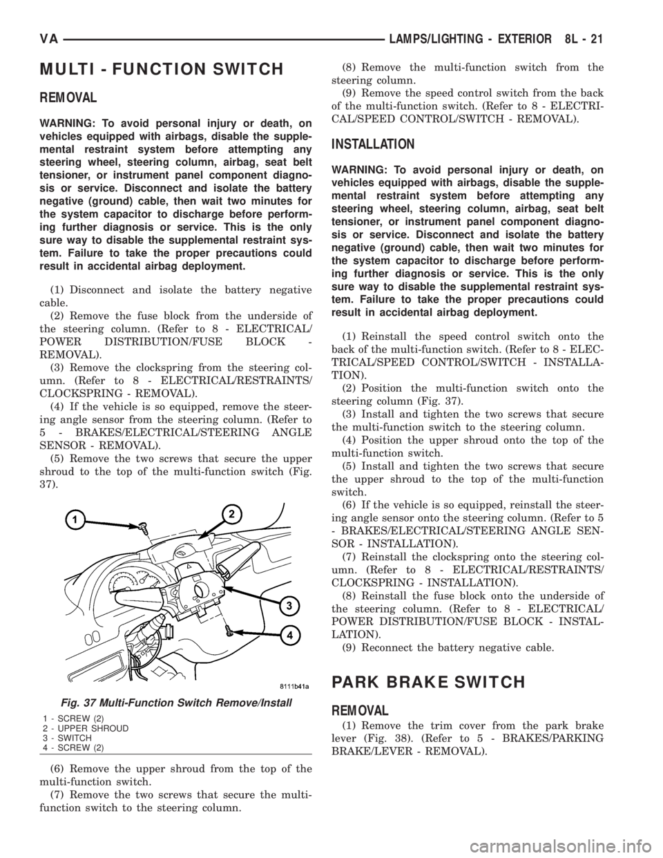
(5) Remove the two screws that secure the upper
shroud to the top of the multi-function switch (Fig.
37).
(6) Remove the upper shroud from the top of the
multi-function switch.
(7) Remove the two screws that secure the multi-
function switch to the steering column.(8) Remove the multi-function switch from the
steering column.
(9) Remove the speed control switch from the back
of the multi-function switch. (Refer to 8 - ELECTRI-
CAL/SPEED CONTROL/SWITCH - REMOVAL).
INSTALLATION
WARNING: To avoid personal injury or death, on
vehicles equipped with airbags, disable the supple-
mental restraint system before attempting any
steering wheel, steering column, airbag, seat belt
tensioner, or instrument panel component diagno-
sis or service. Disconnect and isolate the battery
negative (ground) cable, then wait two minutes for
the system capacitor to discharge before perform-
ing further diagnosis or service. This is the only
sure way to disable the supplemental restraint sys-
tem. Failure to take the proper precautions could
result in accidental airbag deployment.
(1) Reinstall the speed control switch onto the
back of the multi-function switch. (Refer to 8 - ELEC-
TRICAL/SPEED CONTROL/SWITCH - INSTALLA-
TION).
(2) Position the multi-function switch onto the
steering column (Fig. 37).
(3) Install and tighten the two screws that secure
the multi-function switch to the steering column.
(4) Position the upper shroud onto the top of the
multi-function switch.
(5) Install and tighten the two screws that secure
the upper shroud to the top of the multi-function
switch.
(6) If the vehicle is so equipped, reinstall the steer-
ing angle sensor onto the steering column. (Refer to 5
- BRAKES/ELECTRICAL/STEERING ANGLE SEN-
SOR - INSTALLATION).
(7) Reinstall the clockspring onto the steering col-
umn. (Refer to 8 - ELECTRICAL/RESTRAINTS/
CLOCKSPRING - INSTALLATION).
(8) Reinstall the fuse block onto the underside of
the steering column. (Refer to 8 - ELECTRICAL/
POWER DISTRIBUTION/FUSE BLOCK - INSTAL-
LATION).
(9) Reconnect the battery negative cable.
PARK BRAKE SWITCH
REMOVAL
(1) Remove the trim cover from the park brake
lever (Fig. 38). (Refer to 5 - BRAKES/PARKING
BRAKE/LEVER - REMOVAL).
Fig. 37 Multi-Function Switch Remove/Install
1 - SCREW (2)
2 - UPPER SHROUD
3 - SWITCH
4 - SCREW (2)
VALAMPS/LIGHTING - EXTERIOR 8L - 21
Page 1093 of 2305
Component Page
Ignition Lock Switch................... 8W-40
Ignition Switch....................... 8W-10
Instrument Cluster.................... 8W-40
Instrument Panel Socket................ 8W-41
Intake Air Pressure Sensor.............. 8W-30
Intake Air Temperature Sensor........... 8W-30
Interference Suppression Capacitor........ 8W-42
Interior Lamps....................... 8W-44
Interior Light Switches................. 8W-44
Interior Lighting Connector.............. 8W-44
Intrusion Sensors..................... 8W-39
Kickdown Switch...................... 8W-30
Lamp Relays......................... 8W-50
Lateral Acceleration Sensor.............. 8W-35
License Plate Lamps................... 8W-51
Lockeres............................ 8W-31
Low Fuel Pressure Sensor............... 8W-30
Low Pressure Switch................... 8W-42
Map/Reading Lamp Switch.............. 8W-44
Marker Lamp Connector................ 8W-51
Marker Lamps..................... 8W-50, 51
Mass Air Flow Sensor.................. 8W-30
Master Door Lock Switch............... 8W-61
Metering Pump....................... 8W-42
Microphone Connector.................. 8W-55
Multi-Function Switch......... 8W-50, 52, 53, 54
Optional Equipment Relay.............. 8W-11
Oxygen Sensor....................... 8W-30
Panic Alarm Switch.................... 8W-39
Parking Brake Switch.................. 8W-35
Power Distribution Center.............. 8W-10
Power Mirror Motors................... 8W-62
Power Mirror Switch................... 8W-62
Power Window Motors.................. 8W-60
Power Window Switches................ 8W-60
Radio............................... 8W-47
Radio Antenna........................ 8W-47
Radio/Cellular Antenna................. 8W-55
Rain Sensor.......................... 8W-53
Rain Sensor Control Module............. 8W-53
Reading Lamp Connector............... 8W-44
Rear Window Defogger Relay............ 8W-48
Recirculated Air Solenoid Valve........... 8W-42
Refrigerant Pressure Sensor............. 8W-42
Relay Block.......................... 8W-11
Rollover Switch....................... 8W-42
Rollover Switch Assembly............... 8W-42
Roof A/C Blower Fuses................. 8W-42
Roof A/C Blower Stage Relays............ 8W-42
Roof A/C Blowers...................... 8W-42
Roof A/C Compressor Fuse.............. 8W-42Component Page
Roof A/C Control Module................ 8W-42
Roof A/C Fan Fuse.................... 8W-42
Roof A/C Switch....................... 8W-42
Roof A/C Temperature Setting Control..... 8W-42
Roof Fan Motor....................... 8W-42
Roof Fan Switch...................... 8W-42
Roof Thermotronic Control Module........ 8W-42
SKREEM Antenna.................... 8W-39
SKREEM Transponder................. 8W-39
Seat Belt Switch...................... 8W-43
Seat Belt Tensioners................... 8W-43
Security System Module................ 8W-39
Sentry Key Remote Entry Module......... 8W-39
Shifter Assembly...................... 8W-31
Siren............................... 8W-41
Speakers............................ 8W-47
Speed Control Switch.................. 8W-33
Splices.............................. 8W-70
Starter Motor........................ 8W-21
Starter Motor Relay................... 8W-21
Steering Angle Sensor.................. 8W-35
TCS Switch.......................... 8W-35
Tail Lamp Assemblies.................. 8W-51
Temperature Sensor................... 8W-42
Thermotronic Diode.................... 8W-42
Time Delay Relay..................... 8W-44
Towing/Intrusion Sensor On/Off Switch..... 8W-39
Trailer Tow Connector.................. 8W-54
Trailer Tow Control Module.............. 8W-54
Transmission Control Module............ 8W-31
Transmission Relay.................... 8W-31
Turn Signal Relay..................... 8W-52
Turn Signal Switch.................... 8W-50
Turn Signal/Anti-Theft Alarm Relays...... 8W-39
Turn Signals......................... 8W-52
Warm Air Auxiliary Control Module....... 8W-42
Warm Air Auxiliary Heater Assembly...... 8W-42
Washer On/Off Switch.................. 8W-53
Washer Pump Motor-Front.............. 8W-53
Water Cycle Valve..................... 8W-42
Water In Fuel Sensor.................. 8W-30
Wheel Speed Sensors................... 8W-35
Window Defogger Module-Rear........... 8W-48
Window Defogger Switch-Rear........... 8W-48
Window Defoggers..................... 8W-48
Wiper Motor-Front.................... 8W-53
Wiper On/Off Relay.................... 8W-53
Wiper Switch......................... 8W-53
Wiper/Turn Signal/Engine Start Control
Module................... 8W-30, 31, 52, 53
8W - 02 - 2 8W-02 COMPONENT INDEXVA