TEST ACTION APPLICABILITY
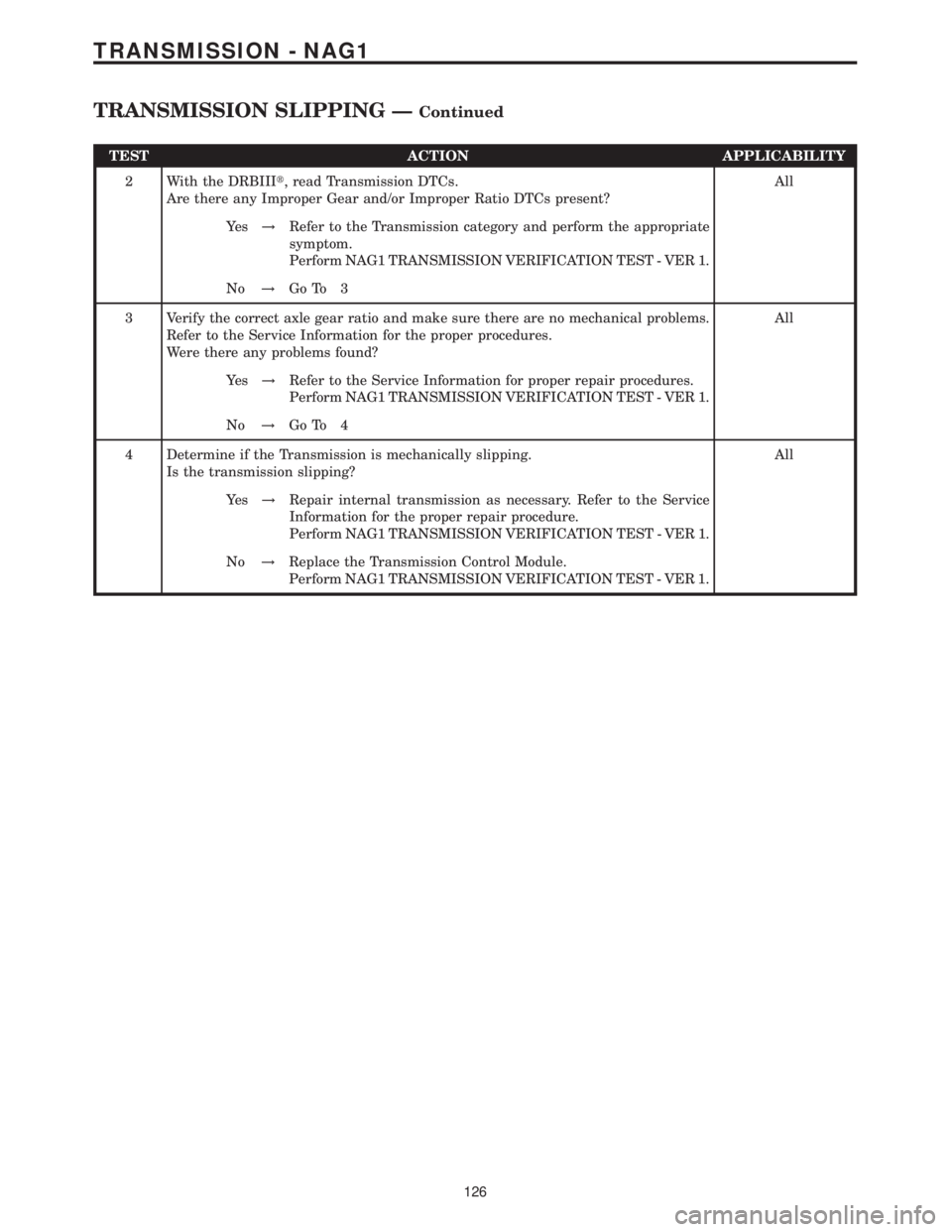
2 With the DRBIIIt, read Transmission DTCs.
Are there any Improper Gear and/or Improper Ratio DTCs present?All
Ye s!Refer to the Transmission category and perform the appropriate
symptom.
Perform NAG1 TRANSMISSION VERIFICATION TEST - VER 1.
No!Go To 3
3 Verify the correct axle gear ratio and make sure there are no mechanical problems.
Refer to the Service Information for the proper procedures.
Were there any problems found?All
Ye s!Refer to the Service Information for proper repair procedures.
Perform NAG1 TRANSMISSION VERIFICATION TEST - VER 1.
No!Go To 4
4 Determine if the Transmission is mechanically slipping.
Is the transmission slipping?All
Ye s!Repair internal transmission as necessary. Refer to the Service
Information for the proper repair procedure.
Perform NAG1 TRANSMISSION VERIFICATION TEST - VER 1.
No!Replace the Transmission Control Module.
Perform NAG1 TRANSMISSION VERIFICATION TEST - VER 1.
126
TRANSMISSION - NAG1
TRANSMISSION SLIPPING ÐContinued
Verification Tests
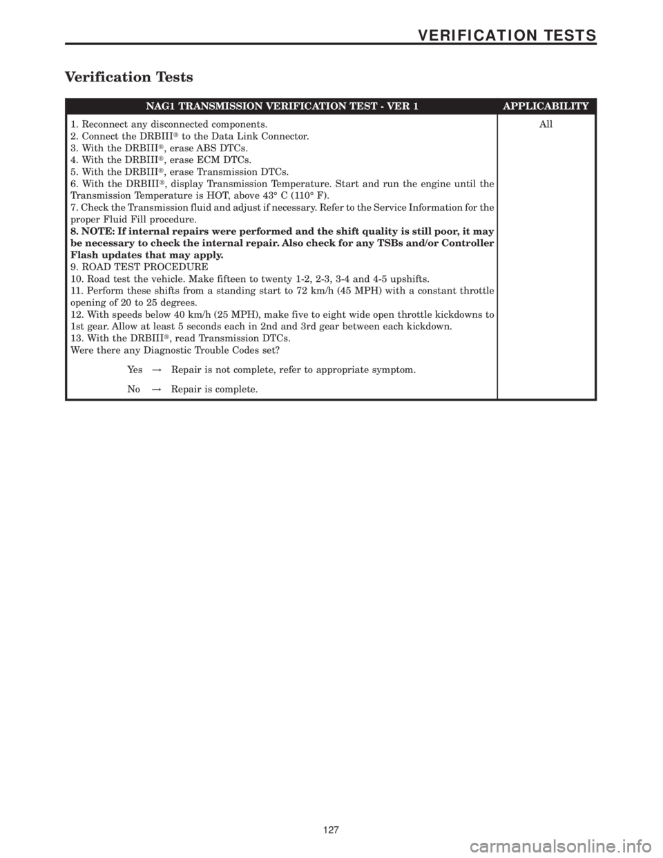
NAG1 TRANSMISSION VERIFICATION TEST - VER 1 APPLICABILITY
1. Reconnect any disconnected components.
2. Connect the DRBIIItto the Data Link Connector.
3. With the DRBIIIt, erase ABS DTCs.
4. With the DRBIIIt, erase ECM DTCs.
5. With the DRBIIIt, erase Transmission DTCs.
6. With the DRBIIIt, display Transmission Temperature. Start and run the engine until the
Transmission Temperature is HOT, above 43É C (110É F).
7. Check the Transmission fluid and adjust if necessary. Refer to the Service Information for the
proper Fluid Fill procedure.
8. NOTE: If internal repairs were performed and the shift quality is still poor, it may
be necessary to check the internal repair. Also check for any TSBs and/or Controller
Flash updates that may apply.
9. ROAD TEST PROCEDURE
10. Road test the vehicle. Make fifteen to twenty 1-2, 2-3, 3-4 and 4-5 upshifts.
11. Perform these shifts from a standing start to 72 km/h (45 MPH) with a constant throttle
opening of 20 to 25 degrees.
12. With speeds below 40 km/h (25 MPH), make five to eight wide open throttle kickdowns to
1st gear. Allow at least 5 seconds each in 2nd and 3rd gear between each kickdown.
13. With the DRBIIIt, read Transmission DTCs.
Were there any Diagnostic Trouble Codes set?All
Ye s!Repair is not complete, refer to appropriate symptom.
No!Repair is complete.
127
VERIFICATION TESTS
9.0 CONNECTOR PINOUTS
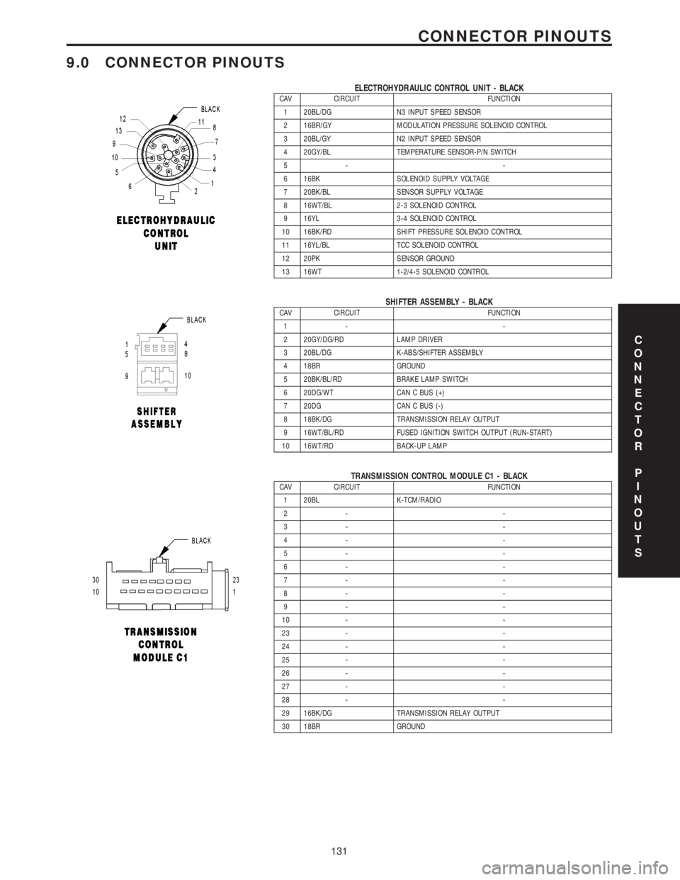
ELECTROHYDRAULIC CONTROL UNIT - BLACKCAV CIRCUIT FUNCTION
1 20BL/DG N3 INPUT SPEED SENSOR
2 16BR/GY MODULATION PRESSURE SOLENOID CONTROL
3 20BL/GY N2 INPUT SPEED SENSOR
4 20GY/BL TEMPERATURE SENSOR-P/N SWITCH
5- -
6 16BK SOLENOID SUPPLY VOLTAGE
7 20BK/BL SENSOR SUPPLY VOLTAGE
8 16WT/BL 2-3 SOLENOID CONTROL
9 16YL 3-4 SOLENOID CONTROL
10 16BK/RD SHIFT PRESSURE SOLENOID CONTROL
11 16YL/BL TCC SOLENOID CONTROL
12 20PK SENSOR GROUND
13 16WT 1-2/4-5 SOLENOID CONTROL
SHIFTER ASSEMBLY - BLACKCAV CIRCUIT FUNCTION
1- -
2 20GY/DG/RD LAMP DRIVER
3 20BL/DG K-ABS/SHIFTER ASSEMBLY
4 18BR GROUND
5 20BK/BL/RD BRAKE LAMP SWITCH
6 20DG/WT CAN C BUS (+)
7 20DG CAN C BUS (-)
8 18BK/DG TRANSMISSION RELAY OUTPUT
9 16WT/BL/RD FUSED IGNITION SWITCH OUTPUT (RUN-START)
10 16WT/RD BACK-UP LAMP
TRANSMISSION CONTROL MODULE C1 - BLACKCAV CIRCUIT FUNCTION
1 20BL K-TCM/RADIO
2- -
3- -
4- -
5- -
6- -
7- -
8- -
9- -
10 - -
23 - -
24 - -
25 - -
26 - -
27 - -
28 - -
29 16BK/DG TRANSMISSION RELAY OUTPUT
30 18BR GROUND
C
O
N
N
E
C
T
O
R
P
I
N
O
U
T
S
131
CONNECTOR PINOUTS
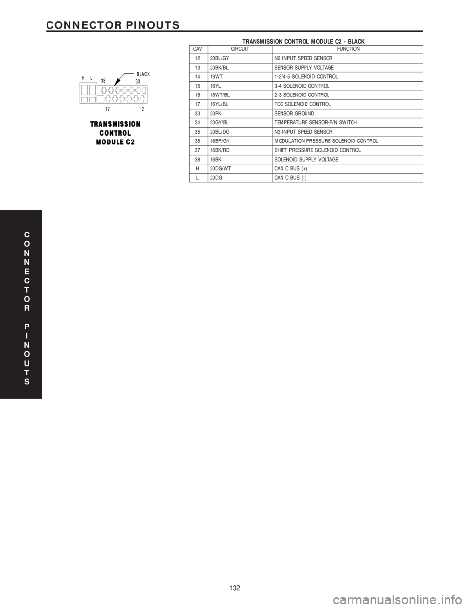
TRANSMISSION CONTROL MODULE C2 - BLACKCAV CIRCUIT FUNCTION
12 20BL/GY N2 INPUT SPEED SENSOR
13 20BK/BL SENSOR SUPPLY VOLTAGE
14 16WT 1-2/4-5 SOLENOID CONTROL
15 16YL 3-4 SOLENOID CONTROL
16 16WT/BL 2-3 SOLENOID CONTROL
17 16YL/BL TCC SOLENOID CONTROL
33 20PK SENSOR GROUND
34 20GY/BL TEMPERATURE SENSOR-P/N SWITCH
35 20BL/DG N3 INPUT SPEED SENSOR
36 16BR/GY MODULATION PRESSURE SOLENOID CONTROL
37 16BK/RD SHIFT PRESSURE SOLENOID CONTROL
38 16BK SOLENOID SUPPLY VOLTAGE
H 20DG/WT CAN C BUS (+)
L 20DG CAN C BUS (-)
C
O
N
N
E
C
T
O
R
P
I
N
O
U
T
S
132
CONNECTOR PINOUTS
