stop start MERCEDES-BENZ SPRINTER 2006 Owner's Manual
[x] Cancel search | Manufacturer: MERCEDES-BENZ, Model Year: 2006, Model line: SPRINTER, Model: MERCEDES-BENZ SPRINTER 2006Pages: 2305, PDF Size: 48.12 MB
Page 1716 of 2305
(3) Install engine cover.
(4) Reconnect negative battery cable.
CRANKSHAFT POSITION SEN-
SOR
DESCRIPTION
The crankshaft position sensor is located opposite
the teeth on the flywheel and uses a non contact
method to record the position of the crankshaft. The
leading edges of each tooth on the flywheel generate
a positive signal in the position sensor, while the
trailing edges generate a negative signal. When the
crankshaft is rotating, an alternating voltage is pro-
duced as a result.
The period of the signal is the time required by the
crankshaft to turn through the gap between two fly-
wheel teeth. The clearance between the crankshaft
position sensor and the teeth of the flywheel is fixed
by the installation.
Two teeth on the flywheel are missing. The result-
ing signal gap is used by the ECM to detect the TDC
position of cylinder number one.
OPERATION
The clearance between the crankshaft position sen-
sor and the flywheel are fixed by the installation
position. Two teeth on the flywheel are missing. The
resulting gap is used by the ECM to detect DTC of
cylinder number one. The crankshaft position is cal-
culated to an accuracy of a fraction of a degree so
that the start and end of injection can occur at
exactly the right moment. The engine speed signal is
also processed by the ECM from the crankshaft sen-
sor. This signal is then transferred to other control
modules over the CAN bus.
If the crankshaft position sensor fails, the ECM
will stop triggering the injectors, the engine will
stall, the engine warning light may or may not illu-
minate, but the engine will not restart.
REMOVAL
(1) Disconnect the negative battery cable.
(2) Unplug the crankshaft wiring harness connec-
tor.
(3) Remove the crankshaft sensor retaining bolt
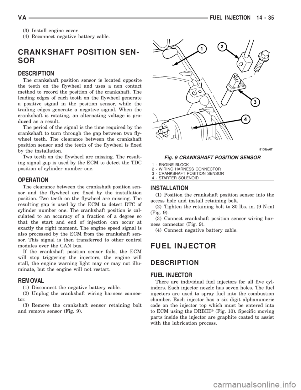
and remove sensor (Fig. 9).
INSTALLATION
(1) Position the crankshaft position sensor into the
access hole and install retaining bolt.
(2) Tighten the retaining bolt to 80 lbs. in. (9 N´m)
(Fig. 9).
(3) Connect crankshaft position sensor wiring har-
ness connector (Fig. 9).
(4) Connect negative battery cable.
FUEL INJECTOR
DESCRIPTION
FUEL INJECTOR
There are individual fuel injectors for all five cyl-
inders. Each injector nozzle has seven holes. The fuel
injectors are used to spray fuel into the combustion
chamber. Each injector has a six digit alphanumeric
code on the injector top which must be entered into
to ECM using the DRBIIIt(Fig. 10). Specific moving
parts inside the injector are graphite coated to assist
with the lubrication process.
Fig. 9 CRANKSHAFT POSITION SENSOR
1 - ENGINE BLOCK
2 - WIRING HARNESS CONNECTOR
3 - CRANKSHAFT POSITION SENSOR
4 - STARTER SOLENOID
VAFUEL INJECTION 14 - 35
Page 1718 of 2305
position against the opening forces applied to its
pressure stage (Fig. 11).
Injector opens (start of injection)
The solenoid valve is energized with the pickup
current which serves to ensure that it open quickly.
The force exerted by the triggered solenoid now
exceeds that of the valve spring and the armature
opens the bleed orifice. Almost immediately, the high-
level pick-up current is reduced to the lower holding
current required for the electromagnet. This is possi-
ble due to the magnetic circuit's air gap now being
smaller. When the bleed orifice opens, fuel can flow
from the valve control chamber into the cavity situ-
ated above it, and from there via the fuel return to
the tank. The bleed orifice prevents complete pres-
sure balance, and the pressure in the valve control
chamber sinks as a result. This leads to the pressure
in the valve-control chamber being lower than that in
the nozzle's chamber volume which is still at the
same pressure level as the rail. The reduced pressure
in the valve-control chamber causes a reduction in
the force exerted on the control plunger, the nozzle
needle open as a result, and injection starts (Fig. 11).
Injector opens fully
The control plunger reaches its upper stop where it
remains supported by a cushion of fuel which is gen-
erated by the flow of fuel between the bleed and feed
orifices. The injector nozzle has now opened fully,
and the fuel is injected into the combustion chamber
at a pressure almost equal to that in the fuel rail
(Fig. 11).
Injector closes (end of injection)
As soon as the solenoid valve is no longer trig-
gered, the valve spring forces the armature down-
wards and the ball closes the bleed orifice. The
armature is a 2±piece design. Here, although the
armature plate is guided by a driver shoulder in its
downward movement, it can ªoverspringº with the
return spring so that it exerts no downwards-acting
forces on the armature and the ball. The closing of
the bleed orifice lead to pressure build up in the con-
trol chamber via the input from the feed orifice. This
pressure is the same as that in the rail and exerts an
increased force on the control plunger through its
end face. This force, together with that of the spring,
now exceeds the force exerted by the chamber volume
and the nozzle needle closes. Injection ceases as soon
as the nozzle needle comes up against its bottom stop
again (Fig. 11).
STANDARD PROCEDURE
STANDARD PROCEDURE - INJECTOR CLASSI-
FICATION
NOTE: Fuel Injectors have different flow rates.
When ALL injectors are removed, re-enter all injec-
tor six digit codes.
The classification of injectors into 3 classes
describes the quantity characteristic of the injector.
This will make it possible in the future to match the
engine software to the tolerances of the injector
within a more narrowly graduated range. Classifica-
tion can be clearly recognized, and assigned only by
means of a DRBIIIt.
Classified injectors can be recognized by the six-
digit alphanumeric code or part number and identifi-
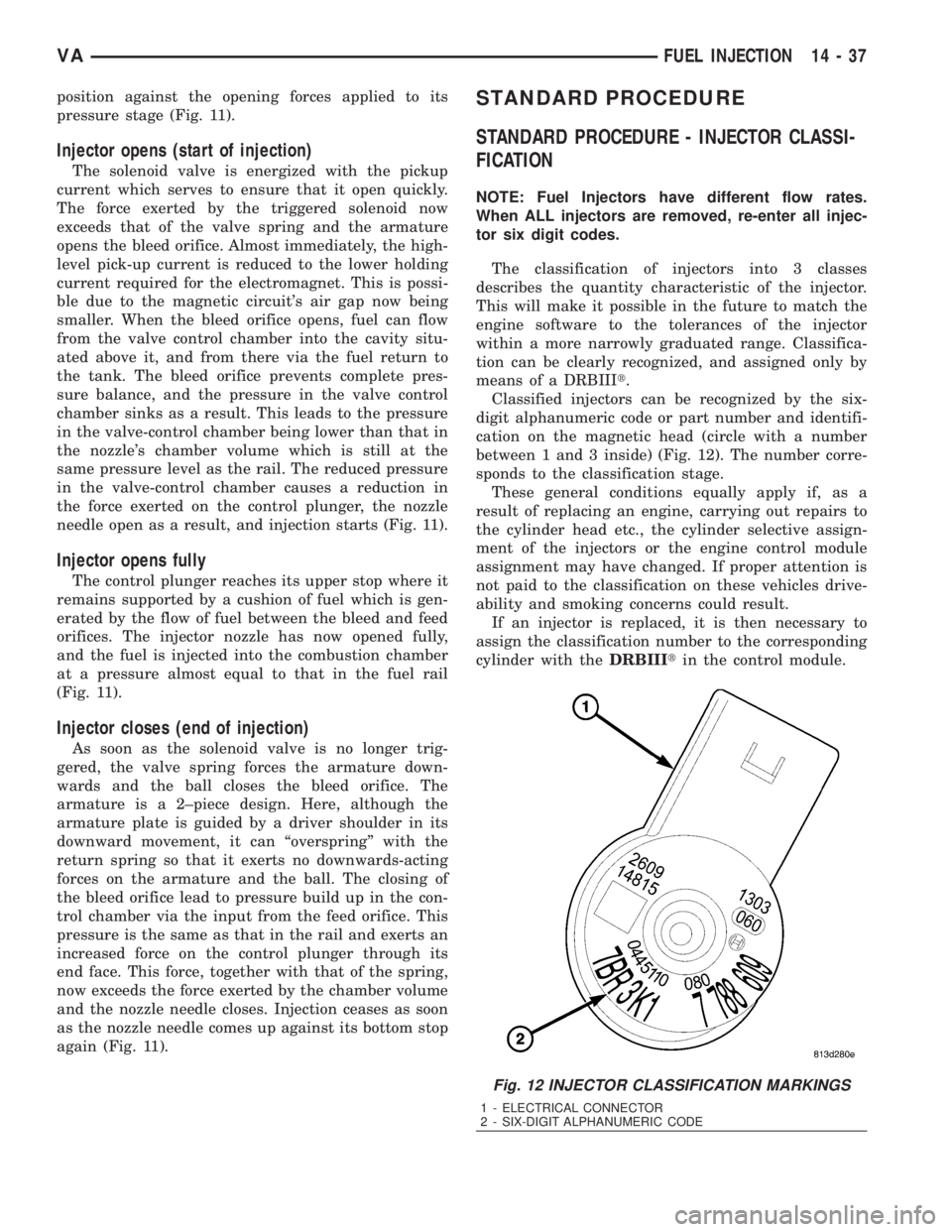
cation on the magnetic head (circle with a number
between 1 and 3 inside) (Fig. 12). The number corre-
sponds to the classification stage.
These general conditions equally apply if, as a
result of replacing an engine, carrying out repairs to
the cylinder head etc., the cylinder selective assign-
ment of the injectors or the engine control module
assignment may have changed. If proper attention is
not paid to the classification on these vehicles drive-
ability and smoking concerns could result.
If an injector is replaced, it is then necessary to
assign the classification number to the corresponding
cylinder with theDRBIIItin the control module.
Fig. 12 INJECTOR CLASSIFICATION MARKINGS
1 - ELECTRICAL CONNECTOR
2 - SIX-DIGIT ALPHANUMERIC CODE
VAFUEL INJECTION 14 - 37
Page 1741 of 2305
(4) Slowly turn the steering wheel lock-to-lock 20
times with the engine off while checking the fluid
level.
NOTE: For vehicles with long return lines or oil
coolers turn wheel 40 times.
(5) Start the engine. With the engine idling main-
tain the fluid level.
(6) Lower the front wheels and let the engine idle
for two minutes.
(7) Turn the steering wheel in both direction and
verify power assist and quiet operation of the pump.
If the fluid is extremely foamy or milky looking,
allow the vehicle to stand a few minutes and repeat
the procedure.
CAUTION: Do not run a vehicle with foamy fluid for
an extended period. This may cause pump damage.
STANDARD PROCEDURE - FLUSHING POWER
STEERING SYSTEM
Flushing is required when the power steering/hy-
draulic booster system fluid has become contami-
nated. Contaminated fluid in the steering/booster
system can cause seal deterioration and affect steer-
ing gear/booster spool valve operation.
(1) Raise the front end of the vehicle off the
ground until the wheels are free to turn.
(2) Remove the return line from the pump.
NOTE: If vehicle is equipped with a hydraulic
booster remove both return lines from the pump.
(3) Plug the return line port/ports at the pump.
(4) Position the return line/lines into a large con-
tainer to catch the fluid.
(5) While an assistant is filling the pump reservoir
start the engine.
(6) With the engine running at idle turn the wheel
back and forth.
NOTE: Do not contact or hold the wheel against the
steering stops.
(7) Run a quart of fluid through the system then
stop the engine and install the return line/lines.
(8) Fill the system with fluid and perform Steering
Pump Initial Operation, (Refer to 19 - STEERING/
PUMP - STANDARD PROCEDURE).
(9) Start the engine and run it for fifteen minutes
then stop the engine.
(10) Remove the return line/lines from the pump
and plug the pump port/ports.
(11) Pour fresh fluid into the reservoir and check
the draining fluid for contamination. If the fluid is
still contaminated, then flush the system again.(12) Install the return line/lines and perform
Steering Pump Initial Operation, (Refer to 19 -
STEERING/PUMP - STANDARD PROCEDURE).
REMOVAL
(1) Remove the belt from the power steering pump.
(2) Siphon as much power steering fluid as possi-
ble out of the reservoir.
(3) Remove the high pressure power steering hose
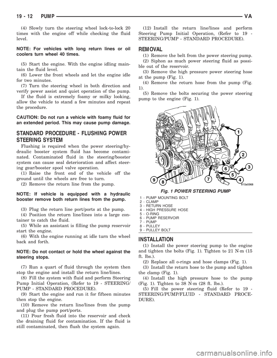
at the pump (Fig. 1).
(4) Remove the return hose from the pump (Fig.
1).
(5) Remove the bolts securing the power steering
pump to the engine (Fig. 1).
INSTALLATION
(1) Install the power steering pump to the engine
and tighten the bolts (Fig. 1). Tighten to 21 N´m (15
ft. lbs.).
(2) Replace all o-rings and hose clamps (Fig. 1).
(3) Install the return hose to the pump and tighten
the clamp (Fig. 1).
(4) Install the high pressure hose to the pump
(Fig. 1). Tighten to 38 N´m (28 ft. lbs.).
(5) Fill the power steering fluid (Refer to 19 -
STEERING/PUMP/FLUID - STANDARD PROCE-
DURE).
Fig. 1 POWER STEERING PUMP
1 - PUMP MOUNTING BOLT
2 - CLAMP
3 - RETURN HOSE
4 - HIGH PRESSURE HOSE
5 - O-RING
6 - PUMP RESERVOIR
7 - PUMP
8 - PULLEY
9 - PULLEY BOLT
19 - 12 PUMPVA
Page 1748 of 2305
flexible adaptation to different vehicle and engine
variants.
EMERGENCY RUNNING FUNCTION
In order to ensure a safe driving state and to pre-
vent damage to the automatic transmission, the TCM
control module switches to limp-home mode in the
event of critical faults. A diagnostic trouble code
(DTC) assigned to the fault is stored in memory. All
solenoid and regulating valves are thus de-energized.
The net effect is:
²The last engaged gear remains engaged.
²The modulating pressure and shift pressures
rise to the maximum levels.
²The torque converter lockup clutch is deacti-
vated.
In order to preserve the operability of the vehicle
to some extent, the hydraulic control can be used to
engage 2nd gear or reverse using the following pro-
cedure:²Stop the vehicle.
²Move selector lever to ªPº.
²Switch off engine.
²Wait at least 10 seconds.
²Start engine.
²Move selector lever to D: 2nd gear.
²Move selector lever to R: Reverse gear.
The limp-home function remains active until the
DTC is rectified or the stored DTC is erased with the
appropriate scan tool. Sporadic faults can be reset
via ignition OFF/ON.
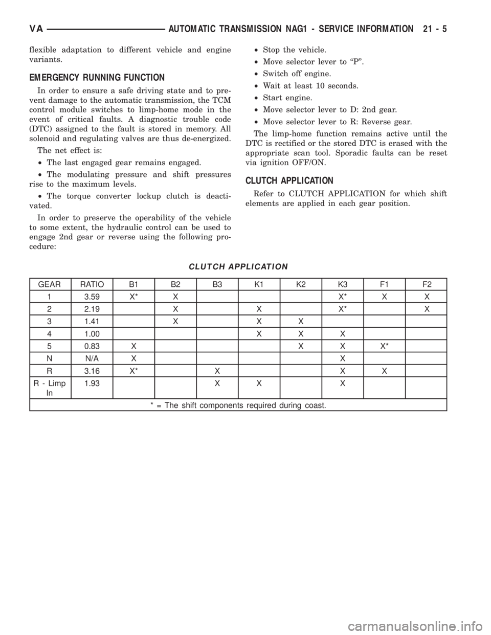
CLUTCH APPLICATION
Refer to CLUTCH APPLICATION for which shift
elements are applied in each gear position.
CLUTCH APPLICATION
GEAR RATIO B1 B2 B3 K1 K2 K3 F1 F2
1 3.59 X* X X* X X
2 2.19 X X X* X
3 1.41 X X X
4 1.00 X X X
5 0.83 X X X X*
N N/A X X
R 3.16 X* X X X
R - Limp
In1.93 X X X
* = The shift components required during coast.
VAAUTOMATIC TRANSMISSION NAG1 - SERVICE INFORMATION 21 - 5
Page 1782 of 2305
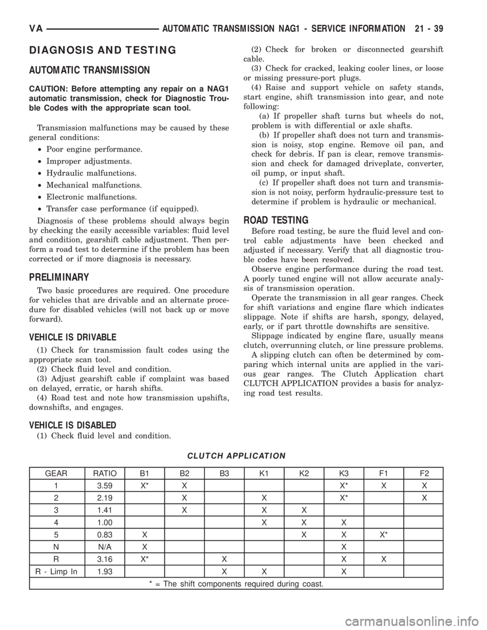
DIAGNOSIS AND TESTING
AUTOMATIC TRANSMISSION
CAUTION: Before attempting any repair on a NAG1
automatic transmission, check for Diagnostic Trou-
ble Codes with the appropriate scan tool.
Transmission malfunctions may be caused by these
general conditions:
²Poor engine performance.
²Improper adjustments.
²Hydraulic malfunctions.
²Mechanical malfunctions.
²Electronic malfunctions.
²Transfer case performance (if equipped).
Diagnosis of these problems should always begin
by checking the easily accessible variables: fluid level
and condition, gearshift cable adjustment. Then per-
form a road test to determine if the problem has been
corrected or if more diagnosis is necessary.
PRELIMINARY
Two basic procedures are required. One procedure
for vehicles that are drivable and an alternate proce-
dure for disabled vehicles (will not back up or move
forward).
VEHICLE IS DRIVABLE
(1) Check for transmission fault codes using the
appropriate scan tool.
(2) Check fluid level and condition.
(3) Adjust gearshift cable if complaint was based
on delayed, erratic, or harsh shifts.
(4) Road test and note how transmission upshifts,
downshifts, and engages.
VEHICLE IS DISABLED
(1) Check fluid level and condition.(2) Check for broken or disconnected gearshift
cable.
(3) Check for cracked, leaking cooler lines, or loose
or missing pressure-port plugs.
(4) Raise and support vehicle on safety stands,
start engine, shift transmission into gear, and note
following:
(a) If propeller shaft turns but wheels do not,
problem is with differential or axle shafts.
(b) If propeller shaft does not turn and transmis-
sion is noisy, stop engine. Remove oil pan, and
check for debris. If pan is clear, remove transmis-
sion and check for damaged driveplate, converter,
oil pump, or input shaft.
(c) If propeller shaft does not turn and transmis-
sion is not noisy, perform hydraulic-pressure test to
determine if problem is hydraulic or mechanical.
ROAD TESTING
Before road testing, be sure the fluid level and con-
trol cable adjustments have been checked and
adjusted if necessary. Verify that all diagnostic trou-
ble codes have been resolved.
Observe engine performance during the road test.
A poorly tuned engine will not allow accurate analy-
sis of transmission operation.
Operate the transmission in all gear ranges. Check
for shift variations and engine flare which indicates
slippage. Note if shifts are harsh, spongy, delayed,
early, or if part throttle downshifts are sensitive.
Slippage indicated by engine flare, usually means
clutch, overrunning clutch, or line pressure problems.
A slipping clutch can often be determined by com-
paring which internal units are applied in the vari-
ous gear ranges. The Clutch Application chart
CLUTCH APPLICATION provides a basis for analyz-
ing road test results.
CLUTCH APPLICATION
GEAR RATIO B1 B2 B3 K1 K2 K3 F1 F2
1 3.59 X* X X* X X
2 2.19 X X X* X
3 1.41 X X X
4 1.00 X X X
5 0.83 X X X X*
N N/A X X
R 3.16 X* X X X
R - Limp In 1.93 X X X
* = The shift components required during coast.
VAAUTOMATIC TRANSMISSION NAG1 - SERVICE INFORMATION 21 - 39
Page 1783 of 2305
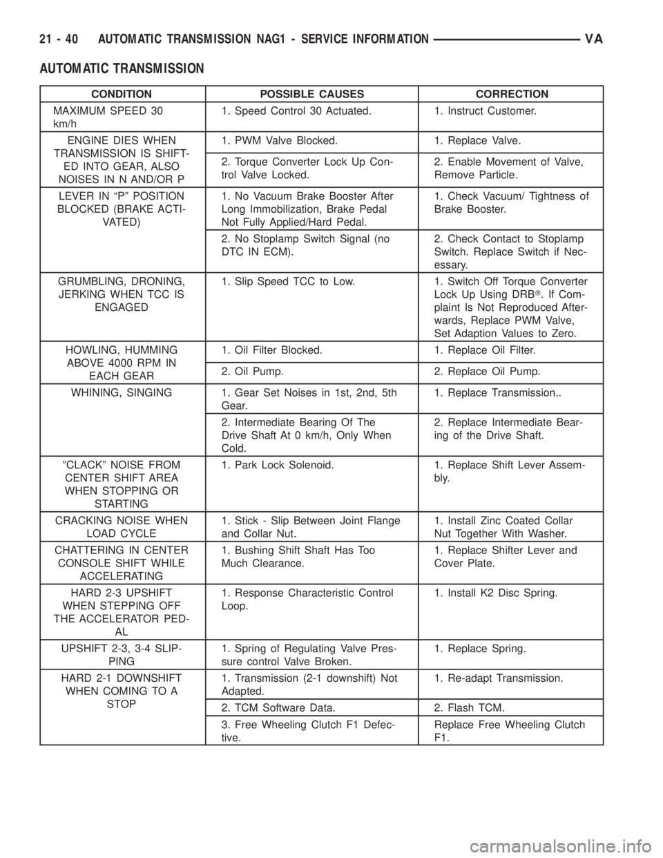
AUTOMATIC TRANSMISSION
CONDITION POSSIBLE CAUSES CORRECTION
MAXIMUM SPEED 30
km/h1. Speed Control 30 Actuated. 1. Instruct Customer.
ENGINE DIES WHEN
TRANSMISSION IS SHIFT-
ED INTO GEAR, ALSO
NOISES IN N AND/OR P1. PWM Valve Blocked. 1. Replace Valve.
2. Torque Converter Lock Up Con-
trol Valve Locked.2. Enable Movement of Valve,
Remove Particle.
LEVER IN ªPº POSITION
BLOCKED (BRAKE ACTI-
VATED)1. No Vacuum Brake Booster After
Long Immobilization, Brake Pedal
Not Fully Applied/Hard Pedal.1. Check Vacuum/ Tightness of
Brake Booster.
2. No Stoplamp Switch Signal (no
DTC IN ECM).2. Check Contact to Stoplamp
Switch. Replace Switch if Nec-
essary.
GRUMBLING, DRONING,
JERKING WHEN TCC IS
ENGAGED1. Slip Speed TCC to Low. 1. Switch Off Torque Converter
Lock Up Using DRBT. If Com-
plaint Is Not Reproduced After-
wards, Replace PWM Valve,
Set Adaption Values to Zero.
HOWLING, HUMMING
ABOVE 4000 RPM IN
EACH GEAR1. Oil Filter Blocked. 1. Replace Oil Filter.
2. Oil Pump. 2. Replace Oil Pump.
WHINING, SINGING 1. Gear Set Noises in 1st, 2nd, 5th
Gear.1. Replace Transmission..
2. Intermediate Bearing Of The
Drive Shaft At 0 km/h, Only When
Cold.2. Replace Intermediate Bear-
ing of the Drive Shaft.
9CLACKº NOISE FROM
CENTER SHIFT AREA
WHEN STOPPING OR
STARTING1. Park Lock Solenoid. 1. Replace Shift Lever Assem-
bly.
CRACKING NOISE WHEN
LOAD CYCLE1. Stick - Slip Between Joint Flange
and Collar Nut.1. Install Zinc Coated Collar
Nut Together With Washer.
CHATTERING IN CENTER
CONSOLE SHIFT WHILE
ACCELERATING1. Bushing Shift Shaft Has Too
Much Clearance.1. Replace Shifter Lever and
Cover Plate.
HARD 2-3 UPSHIFT
WHEN STEPPING OFF
THE ACCELERATOR PED-
AL1. Response Characteristic Control
Loop.1. Install K2 Disc Spring.
UPSHIFT 2-3, 3-4 SLIP-
PING1. Spring of Regulating Valve Pres-
sure control Valve Broken.1. Replace Spring.
HARD 2-1 DOWNSHIFT
WHEN COMING TO A
STOP1. Transmission (2-1 downshift) Not
Adapted.1. Re-adapt Transmission.
2. TCM Software Data. 2. Flash TCM.
3. Free Wheeling Clutch F1 Defec-
tive.Replace Free Wheeling Clutch
F1.
21 - 40 AUTOMATIC TRANSMISSION NAG1 - SERVICE INFORMATIONVA
Page 1875 of 2305
CAUSES OF BURNT FLUID
Burnt, discolored fluid is a result of overheating
which has three primary causes.
1. Internal clutch slippage, usually caused by low
line pressure, inadequate clutch apply pressure, or
clutch seal failure.
2. A result of restricted fluid flow through the
main and/or auxiliary cooler. This condition is usu-
ally the result of a faulty or improperly installed
drainback valve, a damaged oil cooler, or severe
restrictions in the coolers and lines caused by debris
or kinked lines.
3. Heavy duty operation with a vehicle not prop-
erly equipped for this type of operation. Trailer tow-
ing or similar high load operation will overheat the
transmission fluid if the vehicle is improperly
equipped. Such vehicles should have an auxiliary
transmission fluid cooler, a heavy duty cooling sys-
tem, and the engine/axle ratio combination needed to
handle heavy loads.
FLUID CONTAMINATION
Transmission fluid contamination is generally a
result of:
²adding incorrect fluid
²failure to clean dipstick and fill tube when
checking level
²engine coolant entering the fluid
²internal failure that generates debris
²overheat that generates sludge (fluid break-
down)
²failure to replace contaminated converter after
repair
The use of non-recommended fluids can result in
transmission failure. The usual results are erratic
shifts, slippage, abnormal wear and eventual failure
due to fluid breakdown and sludge formation. Avoid
this condition by using recommended fluids only.
The dipstick cap and fill tube should be wiped
clean before checking fluid level. Dirt, grease and
other foreign material on the cap and tube could fall
into the tube if not removed beforehand. Take the
time to wipe the cap and tube clean before withdraw-
ing the dipstick.
Engine coolant in the transmission fluid is gener-
ally caused by a cooler malfunction. The only remedy
is to replace the radiator as the cooler in the radiator
is not a serviceable part. If coolant has circulated
through the transmission, an overhaul is necessary.
The torque converter should be replaced whenever
a failure generates sludge and debris. This is neces-
sary because normal converter flushing procedures
will not remove all contaminants.
STANDARD PROCEDURE
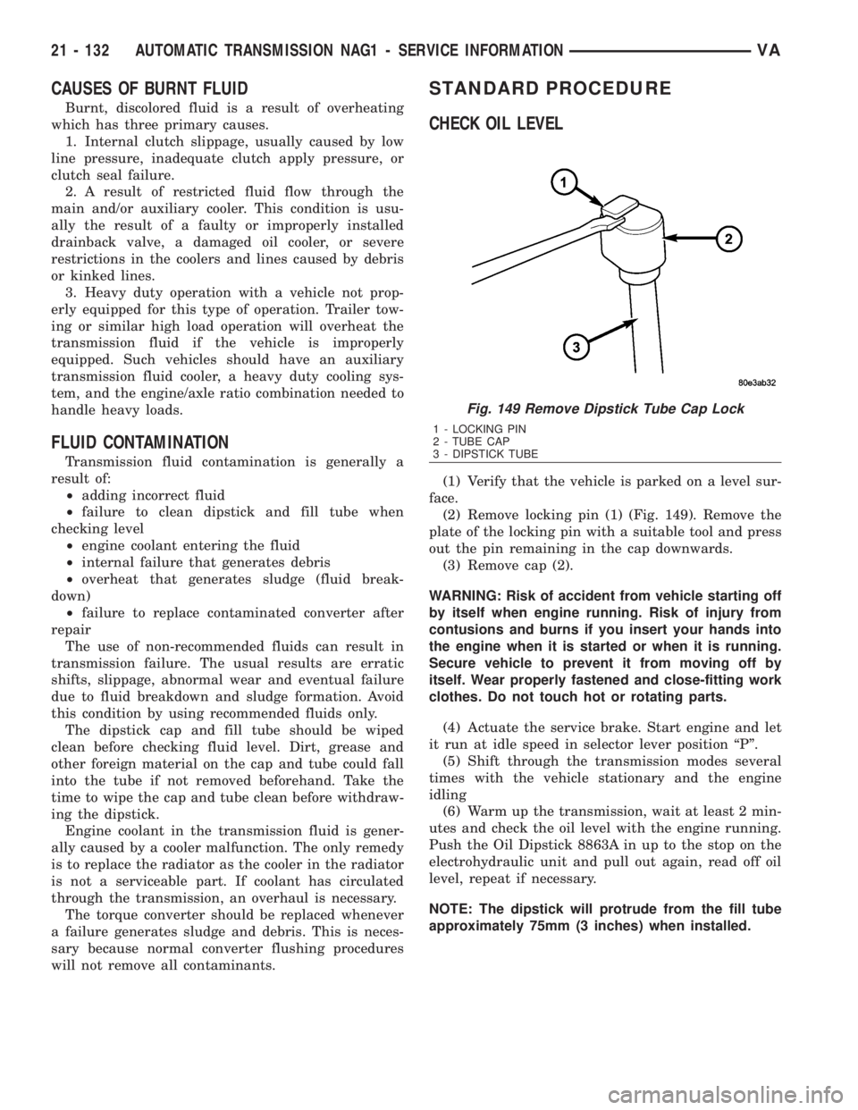
CHECK OIL LEVEL
(1) Verify that the vehicle is parked on a level sur-
face.
(2) Remove locking pin (1) (Fig. 149). Remove the
plate of the locking pin with a suitable tool and press
out the pin remaining in the cap downwards.
(3) Remove cap (2).
WARNING: Risk of accident from vehicle starting off
by itself when engine running. Risk of injury from
contusions and burns if you insert your hands into
the engine when it is started or when it is running.
Secure vehicle to prevent it from moving off by
itself. Wear properly fastened and close-fitting work
clothes. Do not touch hot or rotating parts.
(4) Actuate the service brake. Start engine and let
it run at idle speed in selector lever position ªPº.
(5) Shift through the transmission modes several
times with the vehicle stationary and the engine
idling
(6) Warm up the transmission, wait at least 2 min-
utes and check the oil level with the engine running.
Push the Oil Dipstick 8863A in up to the stop on the
electrohydraulic unit and pull out again, read off oil
level, repeat if necessary.
NOTE: The dipstick will protrude from the fill tube
approximately 75mm (3 inches) when installed.
Fig. 149 Remove Dipstick Tube Cap Lock
1 - LOCKING PIN
2 - TUBE CAP
3 - DIPSTICK TUBE
21 - 132 AUTOMATIC TRANSMISSION NAG1 - SERVICE INFORMATIONVA
Page 1945 of 2305
aligned and sealed. If component alignment or seal-
ing is necessary, refer to the appropriate section of
this group for proper procedures.
WATER LEAK TESTS
WARNING: DO NOT USE ELECTRIC SHOP LIGHTS
OR TOOLS IN WATER TEST AREA. PERSONAL
INJURY CAN RESULT.
When the conditions causing a water leak have
been determined, simulate the conditions as closely
as possible.
²If a leak occurs with the vehicle parked in a
steady light rain, flood the leak area with an open-
ended garden hose.
²If a leak occurs while driving at highway speeds
in a steady rain, test the leak area with a reasonable
velocity stream or fan spray of water. Direct the
spray in a direction comparable to actual conditions.
²If a leak occurs when the vehicle is parked on an
incline, hoist the end or side of the vehicle to simu-
late this condition. This method can be used when
the leak occurs when the vehicle accelerates, stops or
turns. If the leak occurs on acceleration, hoist the
front of the vehicle. If the leak occurs when braking,
hoist the back of the vehicle. If the leak occurs on left
turns, hoist the left side of the vehicle. If the leak
occurs on right turns, hoist the right side of the vehi-
cle. For hoisting recommendations (Refer to LUBRI-
CATION & MAINTENANCE/HOISTING -
STANDARD PROCEDURE).
WATER LEAK DETECTION
To detect a water leak point-of-entry, do a water
test and watch for water tracks or droplets forming
on the inside of the vehicle. If necessary, remove inte-
rior trim covers or panels to gain visual access to the
leak area. If the hose cannot be positioned without
being held, have someone help do the water test.
Some water leaks must be tested for a considerable
length of time to become apparent. When a leak
appears, find the highest point of the water track or
drop. The highest point usually will show the point of
entry. After leak point has been found, repair the
leak and water test to verify that the leak has
stopped.
Locating the entry point of water that is leaking
into a cavity between panels can be difficult. The
trapped water may splash or run from the cavity,
often at a distance from the entry point. Most water
leaks of this type become apparent after accelerating,
stopping, turning, or when on an incline.
MIRROR INSPECTION METHOD
When a leak point area is visually obstructed, use
a suitable mirror to gain visual access. A mirror canalso be used to deflect light to a limited-access area
to assist in locating a leak point.
BRIGHT LIGHT LEAK TEST METHOD
Some water leaks in the luggage compartment can
be detected without water testing. Position the vehi-
cle in a brightly lit area. From inside the darkened
luggage compartment inspect around seals and body
seams. If necessary, have a helper direct a drop light
over the suspected leak areas around the luggage
compartment. If light is visible through a normally
sealed location, water could enter through the open-
ing.
PRESSURIZED LEAK TEST METHOD
When a water leak into the passenger compart-
ment cannot be detected by water testing, pressurize
the passenger compartment and soap test exterior of
the vehicle. To pressurize the passenger compart-
ment, close all doors and windows, start engine, and
set heater control to high blower in HEAT position. If
engine can not be started, connect a charger to the
battery to ensure adequate voltage to the blower.
With interior pressurized, apply dish detergent solu-
tion to suspected leak area on the exterior of the
vehicle. Apply detergent solution with spray device or
soft bristle brush. If soap bubbles occur at a body
seam, joint, seal or gasket, the leak entry point could
be at that location.
DIAGNOSIS AND TESTING - WIND NOISE
Wind noise is the result of most air leaks. Air leaks
can be caused by poor sealing, improper body compo-
nent alignment, body seam porosity, or missing plugs
in the engine compartment or door hinge pillar areas.
All body sealing points should be airtight in normal
driving conditions. Moving sealing surfaces will not
always seal airtight under all conditions. At times,
side glass or door seals will allow wind noise to be
noticed in the passenger compartment during high
cross winds. Over compensating on door or glass
adjustments to stop wind noise that occurs under
severe conditions can cause premature seal wear and
excessive closing or latching effort. After a repair pro-
cedure has been performed, test vehicle to verify
noise has stopped before returning vehicle to use.
VISUAL INSPECTION BEFORE TESTS
Verify that floor and body plugs are in place and
body components are aligned and sealed. If compo-
nent alignment or sealing is necessary, refer to the
appropriate section of this group for proper proce-
dures.
ROAD TESTING WIND NOISE
(1) Drive the vehicle to verify the general location
of the wind noise.
23 - 2 BODYVA
Page 1989 of 2305
(3) Install wedge and install screws.
(4) Close sliding door to adjust closing wedge.
(5) Open door and tighten screws to 10 N´m (89 in.
lbs.).
TRIM PANEL
REMOVAL
Upper
(1) Remove rivets and remove panel.
Lower
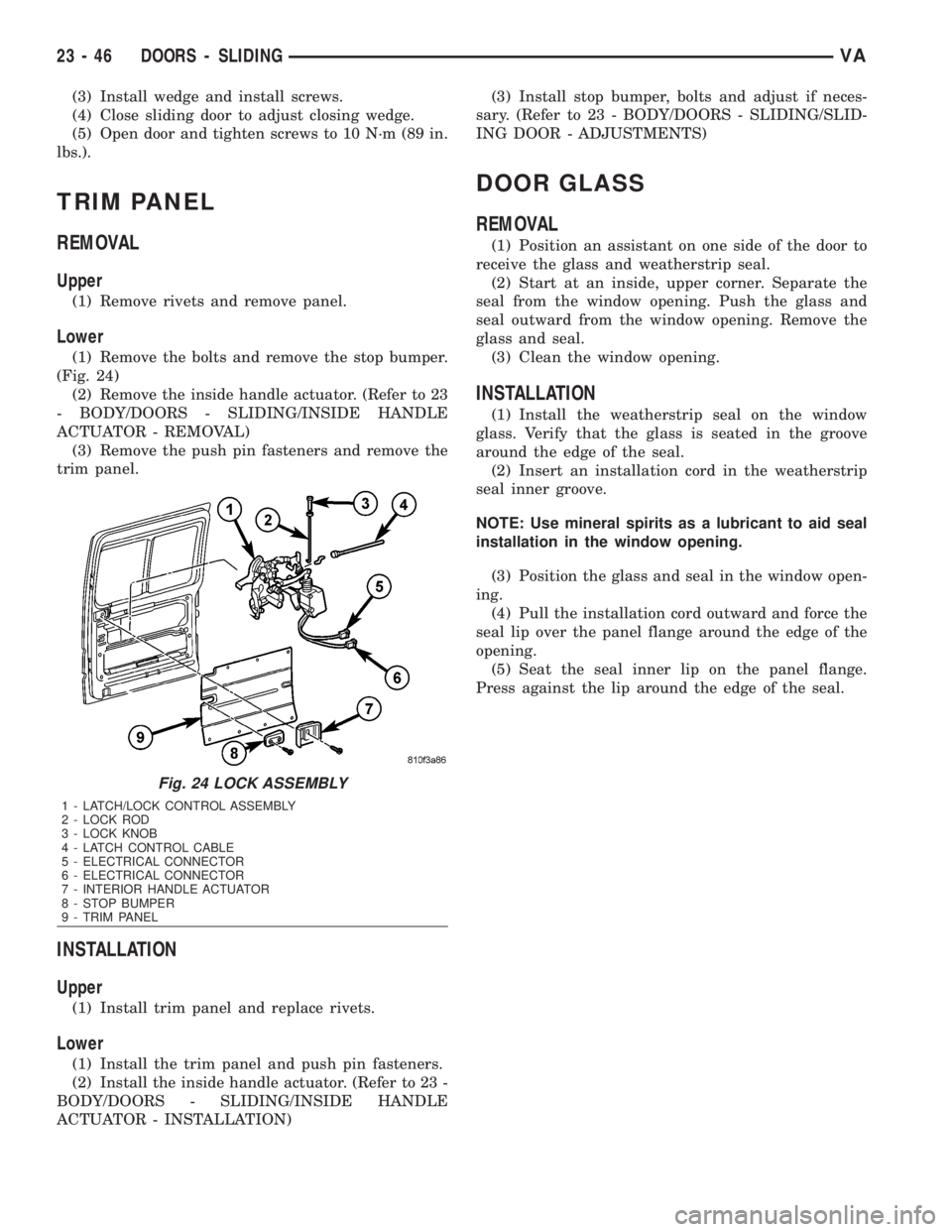
(1) Remove the bolts and remove the stop bumper.
(Fig. 24)
(2) Remove the inside handle actuator. (Refer to 23
- BODY/DOORS - SLIDING/INSIDE HANDLE
ACTUATOR - REMOVAL)
(3) Remove the push pin fasteners and remove the
trim panel.
INSTALLATION
Upper
(1) Install trim panel and replace rivets.
Lower
(1) Install the trim panel and push pin fasteners.
(2) Install the inside handle actuator. (Refer to 23 -
BODY/DOORS - SLIDING/INSIDE HANDLE
ACTUATOR - INSTALLATION)(3) Install stop bumper, bolts and adjust if neces-
sary. (Refer to 23 - BODY/DOORS - SLIDING/SLID-
ING DOOR - ADJUSTMENTS)
DOOR GLASS
REMOVAL
(1) Position an assistant on one side of the door to
receive the glass and weatherstrip seal.
(2) Start at an inside, upper corner. Separate the
seal from the window opening. Push the glass and
seal outward from the window opening. Remove the
glass and seal.
(3) Clean the window opening.
INSTALLATION
(1) Install the weatherstrip seal on the window
glass. Verify that the glass is seated in the groove
around the edge of the seal.
(2) Insert an installation cord in the weatherstrip
seal inner groove.
NOTE: Use mineral spirits as a lubricant to aid seal
installation in the window opening.
(3) Position the glass and seal in the window open-
ing.
(4) Pull the installation cord outward and force the
seal lip over the panel flange around the edge of the
opening.
(5) Seat the seal inner lip on the panel flange.
Press against the lip around the edge of the seal.
Fig. 24 LOCK ASSEMBLY
1 - LATCH/LOCK CONTROL ASSEMBLY
2 - LOCK ROD
3 - LOCK KNOB
4 - LATCH CONTROL CABLE
5 - ELECTRICAL CONNECTOR
6 - ELECTRICAL CONNECTOR
7 - INTERIOR HANDLE ACTUATOR
8 - STOP BUMPER
9 - TRIM PANEL
23 - 46 DOORS - SLIDINGVA
Page 2159 of 2305
INSIDE HANDLE ACTUATOR......23-33, 23-36
INSTRUMENT CLUSTER................8J-2
INSTRUMENT PANEL ANTENNA CABLE....8A-2
INSTRUMENT PANEL ASSEMBLY........23-59
INSTRUMENT PANEL CENTER BEZEL.....23-57
INSTRUMENT PANEL DUCTS...........24-51
INTAKE AIR PRESSURE SENSOR........14-43
INTAKE AIR TEMPERATURE SENSOR.....14-42
INTAKE MANIFOLD....................9-65
INTERIOR..........................23-70
INTERMEDIATE SHAFT.................19-4
INTERNATIONAL SYMBOLS...............0-9
INTERNATIONAL SYMBOLS...........Intro.-2
INTRUSION SENSOR...................8Q-1
IN - CAR TEMPERATURE SENSOR.......24-21
JUMP STARTING.......................0-6
KEY / LOCK CYLINDER.................19-5
KNUCKLE.............................2-5
LAMPS / LIGHTING - EXTERIOR..........8L-2
LAMPS / LIGHTING - INTERIOR.........8L-28
LATCH RELEASE CABLE...............23-52
LATCH RELEASE HANDLE..............23-52
LATCH STRIKER.....................23-18
LATCH ..................23-18, 23-33, 23-52
LATCH / LOCK CONTROL...............23-38
LATERAL ACCELERATION SENSOR........5-33
LEFT MOUNT.........................9-55
LEVER..............................5-26
LICENSE PLATE BRACKET..............23-48
LICENSE PLATE LAMP BULB...........8L-19
LICENSE PLATE LAMP UNIT............8L-19
LINKAGE............................19-9
LIQUID LINE........................24-77
LOCK CYLINDER.....................23-18
LOW BEAM HEADLAMP BULB..........8L-20
LOW FUEL INDICATOR................8J-19
LOW OIL LEVEL INDICATOR............8J-20
LOWER BALL JOINT....................2-6
LOWER CONTROL ARM.................2-6
LOWER ROLLER ARM.................23-37
MAINTENANCE INDICATOR.............8J-20
MAINTENANCE SCHEDULES..............0-8
MALFUNCTION INDICATOR LAMP (MIL) . . . 8J-21
MANIFOLD AIR FLOW (MAF) SENSOR....14-44
MASTER CYLINDER...................5-17
MASTER LOCK SWITCH................8N-1
METRIC SYSTEM...................Intro.-6
MODE DOOR CABLES.................24-21
MULTI - FUNCTION INDICATOR..........8J-22
MULTI - FUNCTION SWITCH............8L-21
O2 SENSOR.........................14-45
ODOMETER.........................8J-22
OIL COOLER & LINES..................9-56
OIL FILTER ..........................9-57
OIL JET .............................9-57
OIL PAN .............................9-58
OIL PUMP...........................9-61
OIL PUMP.........................21-154
OIL SENSOR.........................9-64
OIL ................................9-56
OPENING DIMENSIONS................23-93
OUTPUT SHAFT BEARING.............21-156
OUTPUT SHAFT SEAL................21-159
PAINT TOUCH - UP...................23-77
PAINT.............................23-77
PARK BRAKE INDICATOR..............8J-23
PARK BRAKE SWITCH.................8L-21
PARK LOCK CABLE..................21-160
PARKING BRAKE......................5-23
PASSENGER AIRBAG BRACKET.........8O-27
PASSENGER AIRBAG.................8O-24
PASSENGER HEATED SEAT SWITCH.....8G-13
PEDAL..............................5-19
PISTON & CONNECTING ROD............9-45
PISTON RINGS.......................9-52
PISTONS..........................21-163
PLANETARY GEARTRAIN..............21-164
PLUMBING.........................24-61
POWER BRAKE BOOSTER...............5-19
POWER DISTRIBUTION CENTER.......8W-97-3
POWER DISTRIBUTION..............8W-97-1
POWER MIRROR SWITCH..............8N-3
POWER MIRRORS....................8N-3
POWER OUTLET
...................8W-97-3
POWER WINDOW SWITCH
..............8N-5
POWER WINDOWS
....................8N-5
PROP ROD
.........................23-53
PROPELLER SHAFT
.................3-1, 3-7PUMP.............................19-11
QUARTER TRIM PANEL................23-74
QUARTER WINDOW..................23-84
RADIATOR CROSSMEMBER............23-49
RADIATOR FAN.......................7-14
RADIATOR PRESSURE CAP..............7-19
RADIATOR...........................7-17
RADIO..............................8A-2
RAIN SENSOR CONTROL MODULE......8R-15
RAIN SENSOR.......................8R-12
REAR AXLE..........................3-12
REAR A / C CONDENSER FAN...........24-83
REAR A / C EVAPORATOR..............24-84
REAR A / C EXPANSION VALVE..........24-85
REAR BUMPER - STEP.................13-2
REAR CROSSMEMBER - TRANSMISSION . . 13-11
REAR DISCHARGE LINE...............24-88
REAR FASCIA........................13-3
REAR LATCH STRIKER................23-40
REAR LATCH........................23-40
REAR LIQUID LINE...................24-91
REAR RECEIVER / DRIER..............24-94
REAR REFRIGERANT RESERVOIR........24-95
REAR SEAT BACK SHIELD..............23-82
REAR SEAT BELT & RETRACTOR........8O-28
REAR SEAT BELT BUCKLE.............8O-30
REAR SIDE MARKER LAMP BULB.......8L-22
REAR SUCTION LINE..................24-96
REAR TURN LAMP BULB..............8L-23
REAR VIEW MIRROR.................23-75
REAR WHEEL SPEED SENSOR...........5-31
REAR WINDOW DEFOGGER GRID........8G-7
REAR WINDOW DEFOGGER RELAY.......8G-3
REAR WINDOW DEFOGGER SWITCH......8G-4
REAR...............................2-11
RECEIVER / DRIER...................24-79
RECIRCULATION DOOR ACTUATOR......24-22
REFRIGERANT LINE COUPLER..........24-98
REFRIGERANT OIL...................24-81
REFRIGERANT.......................24-80
RELAY...........................8W-97-4
REMOTE KEYLESS ENTRY
TRANSMITTER.......................8N-1
REPEATER LAMP BULB................8L-23
REPEATER LAMP UNIT................8L-24
RESTRAINTS.........................8O-2
RIGHT MOUNT.......................9-56
ROTORS............................5-20
SAFETY LATCH......................23-53
SEAL - PINION........................3-39
SEAT ADJUSTERS - FRONT.............23-81
SEAT BACK CUSHION / COVER - REAR....23-82
SEAT BACK - FRONT..................23-80
SEAT BELT SWITCH..................8O-31
SEAT BELT TENSIONER................8O-32
SEAT BELT TURNING LOOP ADJUSTER . . . 8O-33
SEAT CUSHION - FRONT...............23-80
SEAT CUSHION / COVER - REAR.........23-83
SEATBELT INDICATOR.................8J-24
SEAT - FRONT.......................23-79
SEAT - REAR........................23-81
SECURITY SYSTEM MODULE............8Q-2
SENTRY KEY REMOTE ENTRY MODULE....8Q-2
SERVO..............................8P-2
SHAFT - AXLE DUAL REAR WHEELS......3-27
SHAFT - AXLE SINGLE REAR WHEEL......3-23
SHIFT MECHANISM..................21-168
SHOCK..............................2-13
SHOES..............................5-27
SIDE CURTAIN AIRBAG................8O-35
SIDE IMPACT SENSOR................8O-39
SIDE VIEW MIRROR..................23-49
SIDE VIEW MIRROR - GLASS...........23-50
SIREN..............................8Q-4
SLIDING DOOR......................23-40
SOLENOID.........................21-171
SPARE TIRE CARRIER.................22-12
SPEAKER............................8A-2
SPEED CONTROL.....................8P-1
SPEEDOMETER......................8J-25
SPRING CLAMP PLATES.................2-8
SPRING SHACKLE.....................2-15
SPRING STOP PLATES..................2-9
SPRING
.........................2-7, 2-14
STABILIZER BAR
..................2-9, 2-15
STABILIZER LINK
.................2-10, 2-16
STABILIZER
.........................23-45
STARTER MOTOR RELAY
..............8F-35STARTER MOTOR....................8F-33
STARTING SYSTEM...................8F-28
STEERING ANGLE SENSOR..............5-32
STEERING COLUMN OPENING COVER....23-68
STEERING WHEEL.....................19-6
STEERING...........................19-1
STEPWELL SCUFF PADS...............23-75
STRUT..............................2-10
SUCTION LINE.......................24-81
SUN VISOR.........................23-76
SUPPORT PLATE......................5-23
SUPPRESSOR FILTER - REAR BLOWER
MOTOR............................24-41
SUPPRESSOR FILTER - REAR
CONDENSER FAN....................24-43
SWITCH.............................8P-3
TACHOMETER.......................8J-25
TAIL LAMP UNIT.....................8L-25
TAILPIPE............................11-3
TEMPERATURE CONTROL..............24-38
TEMPERATURE SENSOR...............24-40
TEMPERATURE SENSOR / PARK -
NEUTRAL CONTACT..................21-176
TERMINAL........................Intro.-10
THREADED HOLE REPAIR.............Intro.-6
TIE ROD END ........................19-10
TIME DELAY RELAY....................8L-35
TIMING CHAIN AND SPROCKETS.........9-72
TIMING CHAIN COVER.................9-70
TIMING CHAIN TENSIONER..............9-81
TIRES..............................22-7
TIRES / WHEELS......................22-1
TONE WHEEL........................5-32
TOP COVER.........................23-67
TOP COVER - CLUSTER................23-64
TOP COVER - TRAY...................23-65
TORQUE CONVERTER HUB SEAL.......21-184
TORQUE CONVERTER................21-178
TORQUE REFERENCES...............Intro.-9
TOWING.............................0-7
TRACTION CONTROL INDICATOR........8J-26
TRACTION CONTROL MALFUNCTION
INDICATOR.........................8J-27
TRAILER HITCH......................13-11
TRANSMISSION CONTROL MODULE......8E-6
TRANSPONDER KEY...................8Q-5
TRIM PANEL.............23-18, 23-34, 23-46
TURBOCHARGER SYSTEM..............11-3
TURBOCHARGER......................11-6
TURN SIGNAL INDICATOR..............8J-27
TURN SIGNAL RELAY.................8L-26
UNDERBODY LINES..................24-100
UPPER ROLLER ARM.................23-36
VACUUM PUMP.......................9-54
VALVE COOLER.......................25-6
VALVE SPRINGS......................9-35
VALVE STEM SEALS...................9-34
VALVE ..............................25-5
VEHICLE IDENTIFICATION NUMBER.....Intro.-1
VEHICLE THEFT SECURITY..............8Q-1
VIBRATION DAMPER...................9-53
VOLTAGE REGULATOR.................8F-24
WAIT - TO - START INDICATOR..........8J-28
WASHER FLUID INDICATOR............8J-29
WASHER FLUID LEVEL SWITCH.........8R-16
WASHER HOSES / TUBES..............8R-18
WASHER NOZZLE....................8R-18
WASHER PUMP / MOTOR..............8R-19
WASHER RESERVOIR.................8R-21
WATER IN FUEL SENSOR..............14-30
WATER PUMP........................7-20
WATER VALVE .......................24-83
WATER - IN - FUEL INDICATOR..........8J-29
WHEEL ALIGNMENT...................2-17
WHEELS...........................22-13
WINDOW MOTOR.....................8N-5
WINDOW REGULATOR - MANUAL........23-21
WINDOW REGULATOR - POWER........23-20
WINDSHIELD........................23-85
WIPER ARM........................8R-23
WIPER BLADE.......................8R-26
WIPER LINKAGE.....................8R-28
WIPER MOTOR......................8R-31
WIPER RELAY.......................8R-34
WIPERS/WASHERS....................8R-2
WIRING DIAGRAM INFORMATION......Intro.-1
YAW RATE SENSOR...................5-35
2 INDEXVA
Description Group-Page Description Group-Page Description Group-Page