sensor MERCEDES-BENZ SPRINTER 2006 Service Manual
[x] Cancel search | Manufacturer: MERCEDES-BENZ, Model Year: 2006, Model line: SPRINTER, Model: MERCEDES-BENZ SPRINTER 2006Pages: 2305, PDF Size: 48.12 MB
Page 999 of 2305
restraint system is functioning normally and that the
repairs are complete. If the airbag indicator fails to
light, or lights and stays on, there is still an active
supplemental restraint system fault or malfunction.
Refer to the appropriate diagnostic information to
diagnose the problem.
NOTE: If the Airbag Control Module (ACM) has been
replaced with a new unit, it will be necessary to ini-
tialize the new ACM. In order to function properly,
the ACM must be programmed for the correct stan-
dard and optional supplemental restraint system
components installed in the vehicle. To initialize the
ACM, a diagnostic scan tool is required. Refer to
the appropriate diagnostic information.
AIRBAG CONTROL MODULE
DESCRIPTION
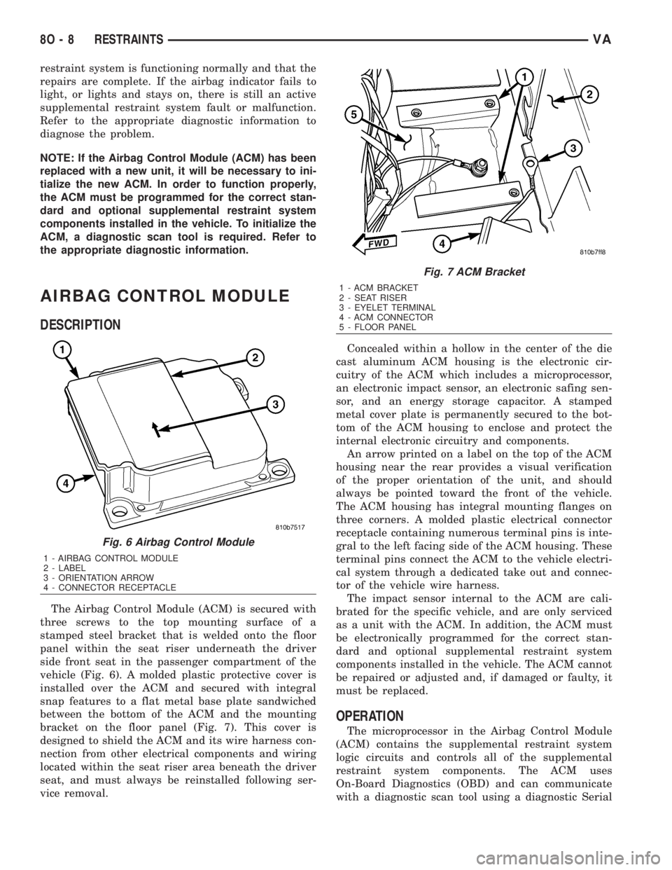
The Airbag Control Module (ACM) is secured with
three screws to the top mounting surface of a
stamped steel bracket that is welded onto the floor
panel within the seat riser underneath the driver
side front seat in the passenger compartment of the
vehicle (Fig. 6). A molded plastic protective cover is
installed over the ACM and secured with integral
snap features to a flat metal base plate sandwiched
between the bottom of the ACM and the mounting
bracket on the floor panel (Fig. 7). This cover is
designed to shield the ACM and its wire harness con-
nection from other electrical components and wiring
located within the seat riser area beneath the driver
seat, and must always be reinstalled following ser-
vice removal.Concealed within a hollow in the center of the die
cast aluminum ACM housing is the electronic cir-
cuitry of the ACM which includes a microprocessor,
an electronic impact sensor, an electronic safing sen-
sor, and an energy storage capacitor. A stamped
metal cover plate is permanently secured to the bot-
tom of the ACM housing to enclose and protect the
internal electronic circuitry and components.
An arrow printed on a label on the top of the ACM
housing near the rear provides a visual verification
of the proper orientation of the unit, and should
always be pointed toward the front of the vehicle.
The ACM housing has integral mounting flanges on
three corners. A molded plastic electrical connector
receptacle containing numerous terminal pins is inte-
gral to the left facing side of the ACM housing. These
terminal pins connect the ACM to the vehicle electri-
cal system through a dedicated take out and connec-
tor of the vehicle wire harness.
The impact sensor internal to the ACM are cali-
brated for the specific vehicle, and are only serviced
as a unit with the ACM. In addition, the ACM must
be electronically programmed for the correct stan-
dard and optional supplemental restraint system
components installed in the vehicle. The ACM cannot
be repaired or adjusted and, if damaged or faulty, it
must be replaced.
OPERATION
The microprocessor in the Airbag Control Module
(ACM) contains the supplemental restraint system
logic circuits and controls all of the supplemental
restraint system components. The ACM uses
On-Board Diagnostics (OBD) and can communicate
with a diagnostic scan tool using a diagnostic Serial
Fig. 6 Airbag Control Module
1 - AIRBAG CONTROL MODULE
2 - LABEL
3 - ORIENTATION ARROW
4 - CONNECTOR RECEPTACLE
Fig. 7 ACM Bracket
1 - ACM BRACKET
2 - SEAT RISER
3 - EYELET TERMINAL
4 - ACM CONNECTOR
5 - FLOOR PANEL
8O - 8 RESTRAINTSVA
Page 1000 of 2305
Communication Interface (SCI) data bus line for sup-
plemental restraint system programming or diagno-
sis and testing through the 16-way Data Link
Connector (DLC) located on the dash panel below the
driver side end of the instrument panel. A hard wired
output from the ACM is used for control of the airbag
indicator in the ElectroMechanical Instrument Clus-
ter (EMIC). (Refer to 8 - ELECTRICAL/INSTRU-
MENT CLUSTER/AIRBAG INDICATOR -
OPERATION).
The ACM microprocessor continuously monitors all
of the supplemental restraint system electrical cir-
cuits to determine the system readiness. If the ACM
detects a monitored system fault, it sets an appropri-
ate Diagnostic Trouble Code (DTC) and sends an out-
put to the EMIC to turn on the airbag indicator. The
ACM illuminates the indicator for about four seconds
each time the ignition switch is turned to the On
position as a bulb test. If the indicator remains illu-
minated for about ten seconds after the ignition
switch is turned to the On position, the ACM has
detected a non-critical fault that poses no danger to
the vehicle occupants. If the airbag indicator illumi-
nates solid (not flashing) while driving or stays on
longer than ten seconds following the bulb test, the
ACM has detected a critical fault that may cause the
airbags not to deploy when required or to deploy
when not required. An active fault only remains for
the duration of the fault, or in some cases, for the
duration of the current ignition switch cycle, while a
stored fault causes a DTC to be stored in memory by
the ACM.
The ACM receives battery current through a fused
ignition switch output circuit. The ACM receives
ground through a ground circuit and take out of the
vehicle wire harness. This take out has an eyelet ter-
minal connector secured by a nut to a ground stud on
the floor panel directly below the ACM within the
driver side seat riser. A case ground is also provided
for the ACM through a ground circuit and eyelet ter-
minal connector secured under the left rear ACM
mounting screw. These connections allow the ACM to
be operational whenever the ignition switch is in the
On position.
The ACM also contains an energy-storage capaci-
tor. When the ignition switch is in the On position,
this capacitor is continually being charged with
enough electrical energy to deploy the supplemental
restraint components for up to one second following a
battery disconnect or failure. The purpose of the
capacitor is to provide backup supplemental restraint
system protection in case there is a loss of battery
current supply to the ACM during an impact.
Two sensors are contained within the ACM, an
electronic impact sensor and a safing sensor. These
electronic sensors are accelerometers that sense the
rate of vehicle deceleration, which provide verifica-
tion of the direction and severity of an impact. Onmodels equipped with optional side curtain airbags,
the ACM also monitors inputs from two remote side
impact sensors located within the left and right front
door step wells to control deployment of the side cur-
tain airbag units.
The safing sensor is an electronic accelerometer
sensor within the ACM that provides an additional
logic input to the ACM microprocessor. The safing
sensor is used to verify the need for a supplemental
restraint deployment by detecting impact energy of a
lesser magnitude than that of the primary electronic
impact sensors, and must exceed a safing threshold
in order for the airbags to deploy. Vehicles equipped
with optional side curtain airbags feature a second
safing sensor within the ACM to provide confirma-
tion to the ACM microprocessor of side impact forces.
This second safing sensor is a bi-directional unit that
detects impact forces from either side of the vehicle.
Pre-programmed decision algorithms in the ACM
microprocessor determine when the deceleration rate
as signaled by the impact sensors and the safing sen-
sors indicate an impact that is severe enough to
require supplemental restraint system protection.
When the programmed conditions are met, the ACM
sends the proper electrical signals to deploy the front
airbags and seat belt tensioners and, if the vehicle is
so equipped, either side curtain airbag unit.
The ACM also provides a hard wired electrical
crash signal output following a supplemental
restraint deployment event. This output is used to
signal other electronic modules in the vehicle to pro-
vide their enhanced accident response features,
which include automatically disabling the engine
from running and unlocking all of the doors. How-
ever, these responses are each dependent upon the
circuits, components, and modules controlling these
features remaining intact from collateral damage
incurred during the vehicle impact.
A single ACM is used for all variations of the sup-
plemental restraint system available in this vehicle.
This ACM is programmable and in order to function
properly it must be programmed for the correct vehi-
cle supplemental restraint system equipment using
an initialization procedure. The initialization proce-
dure requires the use of a diagnostic scan tool. Refer
to the appropriate diagnostic information. The hard
wired inputs and outputs for the ACM may be diag-
nosed and tested using conventional diagnostic tools
and procedures. However, conventional diagnostic
methods will not prove conclusive in the diagnosis of
the ACM or the supplemental restraint system. The
most reliable, efficient, and accurate means to diag-
nose the ACM or the supplemental restraint system
requires the use of a diagnostic scan tool. Refer to
the appropriate diagnostic information.
VARESTRAINTS 8O - 9
Page 1001 of 2305
REMOVAL
WARNING: To avoid personal injury or death, on
vehicles equipped with airbags, disable the supple-
mental restraint system before attempting any
steering wheel, steering column, airbag, seat belt
tensioner, impact sensor, or instrument panel com-
ponent diagnosis or service. Disconnect and isolate
the battery negative (ground) cable, then wait two
minutes for the system capacitor to discharge
before performing further diagnosis or service. This
is the only sure way to disable the supplemental
restraint system. Failure to take the proper precau-
tions could result in accidental airbag deployment.
WARNING: To avoid personal injury or death, never
strike or drop the airbag control module as it can
damage the impact sensor or affect its calibration.
The airbag control module contains the impact sen-
sor, which enables the system to deploy the supple-
mental restraints. If an airbag control module is
accidentally dropped during service, the module
must be scrapped and replaced with a new unit.
Failure to observe this warning could result in acci-
dental, incomplete, or improper supplemental
restraint deployment.
(1) Disconnect and isolate the battery negative
cable. Wait two minutes for the system capacitor to
discharge before further service.
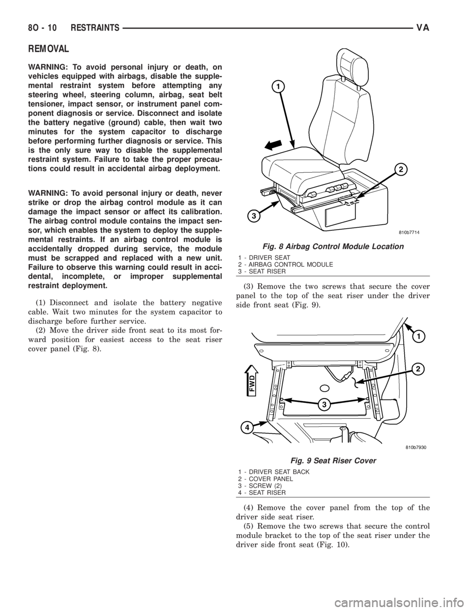
(2) Move the driver side front seat to its most for-
ward position for easiest access to the seat riser
cover panel (Fig. 8).(3) Remove the two screws that secure the cover
panel to the top of the seat riser under the driver
side front seat (Fig. 9).
(4) Remove the cover panel from the top of the
driver side seat riser.
(5) Remove the two screws that secure the control
module bracket to the top of the seat riser under the
driver side front seat (Fig. 10).
Fig. 8 Airbag Control Module Location
1 - DRIVER SEAT
2 - AIRBAG CONTROL MODULE
3 - SEAT RISER
Fig. 9 Seat Riser Cover
1 - DRIVER SEAT BACK
2 - COVER PANEL
3 - SCREW (2)
4 - SEAT RISER
8O - 10 RESTRAINTSVA
Page 1002 of 2305
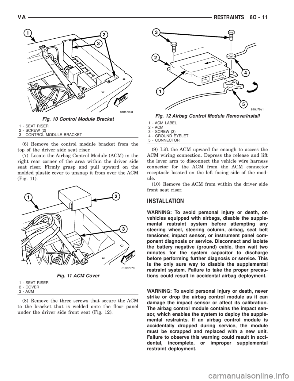
(6) Remove the control module bracket from the
top of the driver side seat riser.
(7) Locate the Airbag Control Module (ACM) in the
right rear corner of the area within the driver side
seat riser. Firmly grasp and pull upward on the
molded plastic cover to unsnap it from over the ACM
(Fig. 11).
(8) Remove the three screws that secure the ACM
to the bracket that is welded onto the floor panel
under the driver side front seat (Fig. 12).(9) Lift the ACM upward far enough to access the
ACM wiring connection. Depress the release and lift
the lever arm to disconnect the vehicle wire harness
connector for the ACM from the ACM connector
receptacle located on the left facing side of the mod-
ule.
(10) Remove the ACM from within the driver side
front seat riser.
INSTALLATION
WARNING: To avoid personal injury or death, on
vehicles equipped with airbags, disable the supple-
mental restraint system before attempting any
steering wheel, steering column, airbag, seat belt
tensioner, impact sensor, or instrument panel com-
ponent diagnosis or service. Disconnect and isolate
the battery negative (ground) cable, then wait two
minutes for the system capacitor to discharge
before performing further diagnosis or service. This
is the only sure way to disable the supplemental
restraint system. Failure to take the proper precau-
tions could result in accidental airbag deployment.
WARNING: To avoid personal injury or death, never
strike or drop the airbag control module as it can
damage the impact sensor or affect its calibration.
The airbag control module contains the impact sen-
sor, which enables the system to deploy the supple-
mental restraints. If an airbag control module is
accidentally dropped during service, the module
must be scrapped and replaced with a new unit.
Failure to observe this warning could result in acci-
dental, incomplete, or improper supplemental
restraint deployment.
Fig. 10 Control Module Bracket
1 - SEAT RISER
2 - SCREW (2)
3 - CONTROL MODULE BRACKET
Fig. 11 ACM Cover
1 - SEAT RISER
2 - COVER
3 - ACM
Fig. 12 Airbag Control Module Remove/Install
1 - ACM LABEL
2 - ACM
3 - SCREW (3)
4 - GROUND EYELET
5 - CONNECTOR
VARESTRAINTS 8O - 11
Page 1005 of 2305
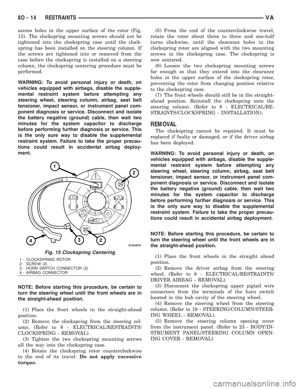
access holes in the upper surface of the rotor (Fig.
15). The clockspring mounting screws should not be
tightened into the clockspring case until the clock-
spring has been installed on the steering column. If
the screws are tightened into or removed from the
case before the clockspring is installed on a steering
column, the clockspring centering procedure must be
performed.
WARNING: To avoid personal injury or death, on
vehicles equipped with airbags, disable the supple-
mental restraint system before attempting any
steering wheel, steering column, airbag, seat belt
tensioner, impact sensor, or instrument panel com-
ponent diagnosis or service. Disconnect and isolate
the battery negative (ground) cable, then wait two
minutes for the system capacitor to discharge
before performing further diagnosis or service. This
is the only sure way to disable the supplemental
restraint system. Failure to take the proper precau-
tions could result in accidental airbag deploy-
ment.
NOTE: Before starting this procedure, be certain to
turn the steering wheel until the front wheels are in
the straight-ahead position.
(1) Place the front wheels in the straight-ahead
position.
(2) Remove the clockspring from the steering col-
umn. (Refer to 8 - ELECTRICAL/RESTRAINTS/
CLOCKSPRING - REMOVAL).
(3) Tighten the two clockspring mounting screws
all the way into the clockspring case.
(4) Rotate the clockspring rotor counterclockwise
to the end of its travel.Do not apply excessive
torque.(5) From the end of the counterclockwise travel,
rotate the rotor about three to three and one-half
turns clockwise, until the clearance holes in the
clockspring rotor are aligned with the two mounting
screws in the clockspring case. The clockspring is
now centered.
(6) Loosen the two clockspring mounting screws
far enough so that they extend into the clearance
holes in the upper surface of the clockspring rotor,
preventing the rotor from changing position relative
to the clockspring case.
(7) The front wheels should still be in the straight-
ahead position. Reinstall the clockspring onto the
steering column. (Refer to 8 - ELECTRICAL/RE-
STRAINTS/CLOCKSPRING - INSTALLATION).
REMOVAL
The clockspring cannot be repaired. It must be
replaced if faulty or damaged, or if the driver airbag
has been deployed.
WARNING: To avoid personal injury or death, on
vehicles equipped with airbags, disable the supple-
mental restraint system before attempting any
steering wheel, steering column, airbag, seat belt
tensioner, impact sensor, or instrument panel com-
ponent diagnosis or service. Disconnect and isolate
the battery negative (ground) cable, then wait two
minutes for the system capacitor to discharge
before performing further diagnosis or service. This
is the only sure way to disable the supplemental
restraint system. Failure to take the proper precau-
tions could result in accidental airbag deployment.
NOTE: Before starting this procedure, be certain to
turn the steering wheel until the front wheels are in
the straight-ahead position.
(1) Place the front wheels in the straight ahead
position.
(2) Remove the driver airbag from the steering
wheel. (Refer to 8 - ELECTRICAL/RESTRAINTS/
DRIVER AIRBAG - REMOVAL).
(3) Disconnect the clockspring upper pigtail wire
connectors from the terminals of the horn switch
located in the hub cavity of the steering wheel.
(4) Remove the steering wheel from the steering
column. (Refer to 19 - STEERING/COLUMN/STEER-
ING WHEEL - REMOVAL).
(5) Remove the steering column opening cover
from the instrument panel. (Refer to 23 - BODY/IN-
STRUMENT PANEL/STEERING COLUMN OPEN-
ING COVER - REMOVAL).
Fig. 15 Clockspring Centering
1 - CLOCKSPRING ROTOR
2 - SCREW (2)
3 - HORN SWITCH CONNECTOR (2)
4 - AIRBAG CONNECTOR
8O - 14 RESTRAINTSVA
Page 1006 of 2305
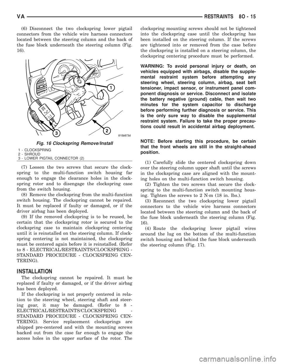
(6) Disconnect the two clockspring lower pigtail
connectors from the vehicle wire harness connectors
located between the steering column and the back of
the fuse block underneath the steering column (Fig.
16).
(7) Loosen the two screws that secure the clock-
spring to the multi-function switch housing far
enough to engage the clearance holes in the clock-
spring rotor and to disengage the clockspring case
from the switch housing.
(8) Remove the clockspring from the multi-function
switch housing. The clockspring cannot be repaired.
It must be replaced if faulty or damaged, or if the
driver airbag has been deployed.
(9) If the removed clockspring is to be reused, be
certain that the clockspring rotor is secured to the
clockspring case to maintain clockspring centering
until it is reinstalled on the steering column. If clock-
spring centering is not maintained, the clockspring
must be centered again before it is reinstalled. (Refer
to 8 - ELECTRICAL/RESTRAINTS/CLOCKSPRING -
STANDARD PROCEDURE - CLOCKSPRING CEN-
TERING).
INSTALLATION
The clockspring cannot be repaired. It must be
replaced if faulty or damaged, or if the driver airbag
has been deployed.
If the clockspring is not properly centered in rela-
tion to the steering wheel, steering shaft and steer-
ing gear, it may be damaged. (Refer to 8 -
ELECTRICAL/RESTRAINTS/CLOCKSPRING -
STANDARD PROCEDURE - CLOCKSPRING CEN-
TERING). Service replacement clocksprings are
shipped pre-centered and with the mounting screws
backed out from the case far enough to engage the
access holes in the upper surface of the rotor. Theclockspring mounting screws should not be tightened
into the clockspring case until the clockspring has
been installed on the steering column. If the screws
are tightened into or removed from the case before
the clockspring is installed on a steering column, the
clockspring centering procedure must be performed.
WARNING: To avoid personal injury or death, on
vehicles equipped with airbags, disable the supple-
mental restraint system before attempting any
steering wheel, steering column, airbag, seat belt
tensioner, impact sensor, or instrument panel com-
ponent diagnosis or service. Disconnect and isolate
the battery negative (ground) cable, then wait two
minutes for the system capacitor to discharge
before performing further diagnosis or service. This
is the only sure way to disable the supplemental
restraint system. Failure to take the proper precau-
tions could result in accidental airbag deployment.
NOTE: Before starting this procedure, be certain
that the front wheels are still in the straight-ahead
position.
(1) Carefully slide the centered clockspring down
over the steering column upper shaft until the screws
in the clockspring case are aligned with the mount-
ing holes on the multi-function switch housing.
(2) Tighten the two screws that secure the clock-
spring to the multi-function switch mounting hous-
ing. Tighten the screws to 2 N´m (18 in. lbs.).
(3) Reconnect the two clockspring lower pigtail
connectors to the vehicle wire harness connectors
located between the steering column and the back of
the fuse block underneath the steering column (Fig.
16).
(4) Route the clockspring lower pigtail wires
around the lug on the bottom of the multi-function
switch housing and behind the fuse block underneath
the steering column (Fig. 17).
Fig. 16 Clockspring Remove/Install
1 - CLOCKSPRING
2 - SHROUD
3 - LOWER PIGTAIL CONNECTOR (2)
VARESTRAINTS 8O - 15
Page 1009 of 2305
sealed within the airbag inflator. Typically, all poten-
tially hazardous chemicals are burned during an air-
bag deployment event. The inert gas that is produced
when the chemicals are burned is harmless. How-
ever, a small amount of residue from the burned
chemicals may cause some temporary discomfort if it
contacts the skin, eyes, or breathing passages. If skin
or eye irritation is noted, rinse the affected area with
plenty of cool, clean water. If breathing passages are
irritated, move to another area where there is plenty
of clean, fresh air to breath. If the irritation is not
alleviated by these actions, contact a physician.
REMOVAL
The following procedure is for replacement of a
faulty or damaged driver airbag. If the airbag is
faulty or damaged, but not deployed, review the rec-
ommended procedures for handling non-deployed
supplemental restraints. (Refer to 8 - ELECTRICAL/
RESTRAINTS - STANDARD PROCEDURE - HAN-
DLING NON-DEPLOYED SUPPLEMENTAL
RESTRAINTS). If the driver airbag has been
deployed, review the recommended procedures for
service after a supplemental restraint deployment
before removing the airbag from the vehicle. (Refer to
8 - ELECTRICAL/RESTRAINTS - STANDARD PRO-
CEDURE - SERVICE AFTER A SUPPLEMENTAL
RESTRAINT DEPLOYMENT).
WARNING: To avoid personal injury or death, on
vehicles equipped with airbags, disable the supple-
mental restraint system before attempting any
steering wheel, steering column, airbag, seat belt
tensioner, impact sensor, or instrument panel com-
ponent diagnosis or service. Disconnect and isolate
the battery negative (ground) cable, then wait two
minutes for the system capacitor to discharge
before performing further diagnosis or service. This
is the only sure way to disable the supplemental
restraint system. Failure to take the proper precau-
tions could result in accidental airbag deployment.
WARNING: To avoid personal injury or death, when
removing a deployed airbag, rubber gloves, eye
protection, and a long-sleeved shirt should be
worn. There may be deposits on the airbag cushion
and other interior surfaces. In large doses, these
deposits may cause irritation to the skin and eyes.
(1) Disconnect and isolate the battery negative
cable. Wait two minutes for the system capacitor to
discharge before further service.
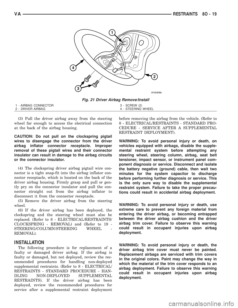
(2) From the underside of the steering wheel,
remove the two screws that secure the driver airbag
to the horn switch armature within the hub cavity of
the steering wheel (Fig. 21).
8O - 18 RESTRAINTSVA
Page 1010 of 2305
(3) Pull the driver airbag away from the steering
wheel far enough to access the electrical connection
at the back of the airbag housing.
CAUTION: Do not pull on the clockspring pigtail
wires to disengage the connector from the driver
airbag inflator connector receptacle. Improper
removal of these pigtail wires and their connector
insulator can result in damage to the airbag circuits
or the connector insulator.
(4) The clockspring driver airbag pigtail wire con-
nector is a tight snap-fit into the airbag inflator con-
nector receptacle, which is located on the back of the
driver airbag housing. Firmly grasp and pull or gen-
tly pry on the connector insulator and pull the con-
nector straight out from the airbag inflator to
disconnect it from the connector receptacle.
(5) Remove the driver airbag from the steering
wheel.
(6) If the driver airbag has been deployed, the
clockspring and the steering wheel must also be
replaced. (Refer to 8 - ELECTRICAL/RESTRAINTS/
CLOCKSPRING - REMOVAL) and (Refer to 19 -
STEERING/COLUMN/STEERING WHEEL -
REMOVAL).
INSTALLATION
The following procedure is for replacement of a
faulty or damaged driver airbag. If the airbag is
faulty or damaged, but not deployed, review the rec-
ommended procedures for handling non-deployed
supplemental restraints. (Refer to 8 - ELECTRICAL/
RESTRAINTS - STANDARD PROCEDURE - HAN-
DLING NON-DEPLOYED SUPPLEMENTAL
RESTRAINTS). If the driver airbag has been
deployed, review the recommended procedures for
service after a supplemental restraint deploymentbefore removing the airbag from the vehicle. (Refer to
8 - ELECTRICAL/RESTRAINTS - STANDARD PRO-
CEDURE - SERVICE AFTER A SUPPLEMENTAL
RESTRAINT DEPLOYMENT).
WARNING: To avoid personal injury or death, on
vehicles equipped with airbags, disable the supple-
mental restraint system before attempting any
steering wheel, steering column, airbag, seat belt
tensioner, impact sensor, or instrument panel com-
ponent diagnosis or service. Disconnect and isolate
the battery negative (ground) cable, then wait two
minutes for the system capacitor to discharge
before performing further diagnosis or service. This
is the only sure way to disable the supplemental
restraint system. Failure to take the proper precau-
tions could result in accidental airbag deployment.
WARNING: To avoid personal injury or death, use
extreme care to prevent any foreign material from
entering the driver airbag, or becoming entrapped
between the driver airbag cushion and the driver
airbag trim cover. Failure to observe this warning
could result in occupant injuries upon airbag
deployment.
WARNING: To avoid personal injury or death, the
driver airbag trim cover must never be painted.
Replacement airbags are serviced with trim covers
in the original colors. Paint may change the way in
which the material of the trim cover responds to an
airbag deployment. Failure to observe this warning
could result in occupant injuries upon airbag
deployment.
Fig. 21 Driver Airbag Remove/Install
1 - AIRBAG CONNECTOR
2 - DRIVER AIRBAG3 - SCREW (2)
4 - STEERING WHEEL
VARESTRAINTS 8O - 19
Page 1011 of 2305
(1) Position the driver airbag close enough to the
steering wheel to reconnect the clockspring driver
airbag pigtail wire connector at the back of the air-
bag housing.
(2) When installing the driver airbag, reconnect
the clockspring driver airbag pigtail wire connector
to the airbag inflator connector receptacle by press-
ing straight in on the connector (Fig. 21). You can be
certain that the connector is fully engaged by listen-
ing carefully for a distinct, audible click as the con-
nector snaps into place.
(3) Carefully position the driver airbag in the
steering wheel. Be certain that the clockspring pig-
tail wire and horn switch wires in the steering wheel
hub area are not pinched between the driver airbag
and the horn switch armature.
(4) From the underside of the steering wheel,
install and tighten the two screws that secure the
driver airbag to the horn switch armature within the
hub cavity of the steering wheel. Tighten the screws
to 6 N´m (53 in. lbs.).
(5) Do not reconnect the battery negative cable at
this time. The supplemental restraint system verifi-
cation test procedure should be performed following
service of any supplemental restraint system compo-
nent. (Refer to 8 - ELECTRICAL/RESTRAINTS -
STANDARD PROCEDURE - VERIFICATION TEST).
FRONT SEAT BELT & RETRAC-
TOR
REMOVAL
The following procedure is for replacement of a
faulty or damaged front seat belt and retractor unit,
which includes a seat belt tensioner for the driver
side as standard equipment. Vehicles equipped with
an optional passenger airbag also have a seat belt
tensioner for the passenger side. (Refer to 8 - ELEC-
TRICAL/RESTRAINTS/SEAT BELT TENSIONER -
DESCRIPTION). If the seat belt or retractor is faulty
or damaged, but the seat belt tensioner is not
deployed, review the recommended procedures for
handling non-deployed supplemental restraints.
(Refer to 8 - ELECTRICAL/RESTRAINTS - STAN-
DARD PROCEDURE - HANDLING NON-DE-
PLOYED SUPPLEMENTAL RESTRAINTS). If the
seat belt tensioner has been deployed, review the rec-
ommended procedures for service after a supplemen-
tal restraint deployment before removing the front
seat belt and retractor from the vehicle. (Refer to 8 -
ELECTRICAL/RESTRAINTS - STANDARD PROCE-
DURE - SERVICE AFTER A SUPPLEMENTAL
RESTRAINT DEPLOYMENT).
WARNING: To avoid personal injury or death, on
vehicles equipped with airbags, disable the supple-mental restraint system before attempting any
steering wheel, steering column, airbag, seat belt
tensioner, impact sensor, or instrument panel com-
ponent diagnosis or service. Disconnect and isolate
the battery negative (ground) cable, then wait two
minutes for the system capacitor to discharge
before performing further diagnosis or service. This
is the only sure way to disable the supplemental
restraint system. Failure to take the proper precau-
tions could result in accidental airbag deployment.
WARNING: To avoid personal injury or death, during
and following any seat belt service, carefully
inspect all seat belts, buckles, mounting hardware,
retractors, and anchors for proper installation, oper-
ation, or damage. Replace any belt that is cut,
frayed, or torn. Straighten any belt that is twisted.
Tighten any loose fasteners. Replace any belt that
has a damaged or inoperative buckle or retractor.
Replace any belt that has a bent or damaged latch
plate or anchor plate. Never attempt to repair a seat
belt component. Always replace damaged or faulty
seat belt components with the correct, new and
unused replacement parts listed in the
DaimlerChrysler Mopar Parts Catalog.
(1) Move the front seat to its most forward position
for easiest access to the B-pillar trim.
(2) Disconnect and isolate the battery negative
cable. Wait two minutes for the system capacitor to
discharge before further service.
(3) If the vehicle is so equipped, unsnap and
remove the plastic cover from the screw that secures
the front seat belt lower anchor to the outboard side
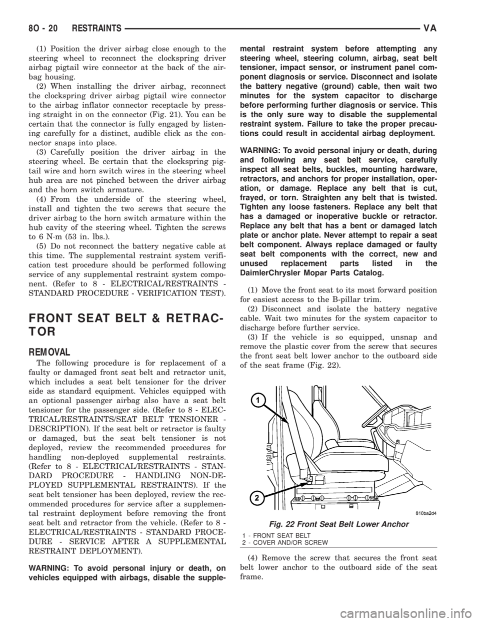
of the seat frame (Fig. 22).
(4) Remove the screw that secures the front seat
belt lower anchor to the outboard side of the seat
frame.
Fig. 22 Front Seat Belt Lower Anchor
1 - FRONT SEAT BELT
2 - COVER AND/OR SCREW
8O - 20 RESTRAINTSVA
Page 1013 of 2305
(12) Remove the screw that secures the front seat
belt retractor to the lower inner B-pillar.
(13) Remove the front seat belt and retractor unit
from the B-pillar.
INSTALLATION
The following procedure is for replacement of a
faulty or damaged front seat belt and retractor unit,
which includes a seat belt tensioner for the driver
side as standard equipment. Vehicles equipped with
an optional passenger airbag also have a seat belt
tensioner for the passenger side. (Refer to 8 - ELEC-
TRICAL/RESTRAINTS/SEAT BELT TENSIONER -
DESCRIPTION). If the seat belt or retractor is faulty
or damaged, but the seat belt tensioner is not
deployed, review the recommended procedures for
handling non-deployed supplemental restraints.
(Refer to 8 - ELECTRICAL/RESTRAINTS - STAN-
DARD PROCEDURE - HANDLING NON-DE-
PLOYED SUPPLEMENTAL RESTRAINTS). If the
seat belt tensioner has been deployed, review the rec-
ommended procedures for service after a supplemen-
tal restraint deployment before removing the front
seat belt and retractor from the vehicle. (Refer to 8 -
ELECTRICAL/RESTRAINTS - STANDARD PROCE-
DURE - SERVICE AFTER A SUPPLEMENTAL
RESTRAINT DEPLOYMENT).
WARNING: To avoid personal injury or death, on
vehicles equipped with airbags, disable the supple-
mental restraint system before attempting anysteering wheel, steering column, airbag, seat belt
tensioner, impact sensor, or instrument panel com-
ponent diagnosis or service. Disconnect and isolate
the battery negative (ground) cable, then wait two
minutes for the system capacitor to discharge
before performing further diagnosis or service. This
is the only sure way to disable the supplemental
restraint system. Failure to take the proper precau-
tions could result in accidental airbag deployment.
WARNING: To avoid personal injury or death, during
and following any seat belt service, carefully
inspect all seat belts, buckles, mounting hardware,
retractors, and anchors for proper installation, oper-
ation, or damage. Replace any belt that is cut,
frayed, or torn. Straighten any belt that is twisted.
Tighten any loose fasteners. Replace any belt that
has a damaged or inoperative buckle or retractor.
Replace any belt that has a bent or damaged latch
plate or anchor plate. Never attempt to repair a seat
belt component. Always replace damaged or faulty
seat belt components with the correct, new and
unused replacement parts listed in the
DaimlerChrysler Mopar Parts Catalog.
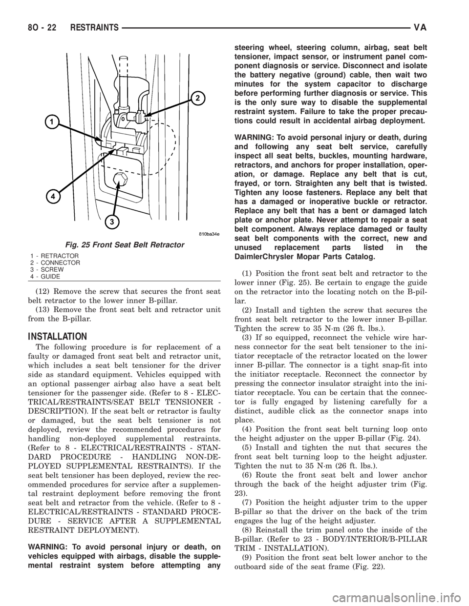
(1) Position the front seat belt and retractor to the
lower inner (Fig. 25). Be certain to engage the guide
on the retractor into the locating notch on the B-pil-
lar.
(2) Install and tighten the screw that secures the
front seat belt retractor to the lower inner B-pillar.
Tighten the screw to 35 N´m (26 ft. lbs.).
(3) If so equipped, reconnect the vehicle wire har-
ness connector for the seat belt tensioner to the ini-
tiator receptacle of the retractor located on the lower
inner B-pillar. The connector is a tight snap-fit into
the initiator receptacle. Reconnect the connector by
pressing the connector insulator straight into the ini-
tiator receptacle. You can be certain that the connec-
tor is fully engaged by listening carefully for a
distinct, audible click as the connector snaps into
place.
(4) Position the front seat belt turning loop onto
the height adjuster on the upper B-pillar (Fig. 24).
(5) Install and tighten the nut that secures the
front seat belt turning loop to the height adjuster.
Tighten the nut to 35 N´m (26 ft. lbs.).
(6) Route the front seat belt and lower anchor
through the back of the height adjuster trim (Fig.
23).
(7) Position the height adjuster trim to the upper
B-pillar so that the driver on the back of the trim
engages the lug of the height adjuster.
(8) Reinstall the trim panel onto the inside of the
B-pillar. (Refer to 23 - BODY/INTERIOR/B-PILLAR
TRIM - INSTALLATION).
(9) Position the front seat belt lower anchor to the
outboard side of the seat frame (Fig. 22).
Fig. 25 Front Seat Belt Retractor
1 - RETRACTOR
2 - CONNECTOR
3 - SCREW
4 - GUIDE
8O - 22 RESTRAINTSVA