transmission MERCEDES-BENZ SPRINTER 2010 MY10 Operator’s Manual
[x] Cancel search | Manufacturer: MERCEDES-BENZ, Model Year: 2010, Model line: SPRINTER, Model: MERCEDES-BENZ SPRINTER 2010Pages: 292, PDF Size: 6.75 MB
Page 246 of 292
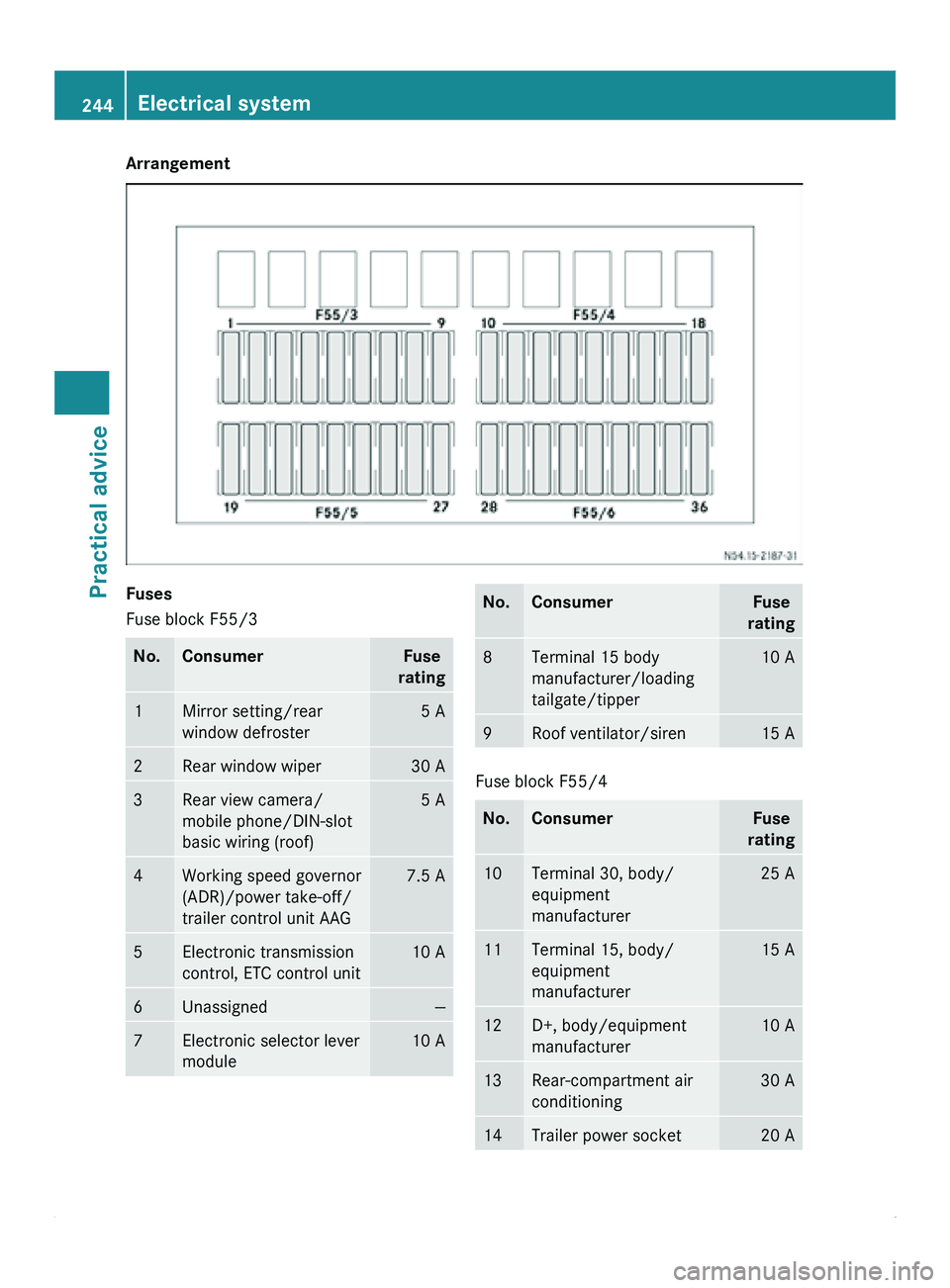
Arrangement
Fuses
Fuse block F55/3
No. Consumer Fuse
rating 1 Mirror setting/rear
window defroster 5 A
2 Rear window wiper 30 A
3 Rear view camera/
mobile phone/DIN-slot
basic wiring (roof) 5 A
4 Working speed governor
(ADR)/power take-off/
trailer control unit AAG 7.5 A
5 Electronic transmission
control, ETC control unit 10 A
6 Unassigned —
7 Electronic selector lever
module 10 A No. Consumer Fuse
rating 8 Terminal 15 body
manufacturer/loading
tailgate/tipper 10 A
9 Roof ventilator/siren 15 A
Fuse block F55/4
No. Consumer Fuse
rating 10 Terminal 30, body/
equipment
manufacturer 25 A
11 Terminal 15, body/
equipment
manufacturer 15 A
12 D+, body/equipment
manufacturer 10 A
13 Rear-compartment air
conditioning 30 A
14 Trailer power socket 20 A244
Electrical systemPractical advice
Page 248 of 292
recycled in an environmentally
responsible manner.
Dispose of old batteries in an
environmentally responsible
manner. Take discharged batteries
to a qualified specialist workshop,
e.g. an authorized Sprinter Dealer,
or to a special collection point for
old batteries.
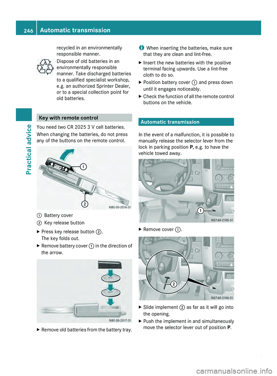
Key with remote control
You need two CR 2025 3 V cell batteries.
When changing the batteries, do not press
any of the buttons on the remote control. 0046
Battery cover
0047 Key release button
X Press key release button 0047.
The key folds out.
X Remove battery cover 0046 in
the direction of
the arrow. X
Remove old batteries from the battery tray. i
When inserting the batteries, make sure
that they are clean and lint-free.
X Insert the new batteries with the positive
terminal facing upwards. Use a lint-free
cloth to do so.
X Position battery cover 0046 and press down
until it engages noticeably.
X Check the function of all the remote control
buttons on the vehicle. Automatic transmission
In the event
of a malfunction, it is possible to
manually release the selector lever from the
lock in parking position P, e.g. to have the
vehicle towed away. X
Remove cover 0046. X
Slide implement 0047 as far as it will go into
the opening.
X Push the implement in and simultaneously
move the selector lever out of position P.246
Automatic transmission
Practical advice
Page 249 of 292
X
Remove implement 0047.
X Refit cover 0046. Jump starting, tow-starting and
towing away
Jump-starting
General notes If the vehicle battery is flat, the engine can be
started from another vehicle using jumper
cables. For this purpose, the vehicle has a
jump-starting connection point in the engine
compartment.
The additional battery in the engine
compartment is
not
suitable for jump-starting
operations. If your vehicle requires jump-
starting, or if you use it to jump-start another
vehicle, use the jump-starting connection
point in the engine compartment. G
Warning
Explosive oxyhydrogen is produced when
batteries are being
charged. When working on
batteries, always make sure that the work
area is well ventilated.
Keep flames and naked lights away from the
battery, and do not smoke.
Prevent the creation of sparks (e.g. when
disconnecting the batteries). Sparks can
ignite the oxyhydrogen gas and cause the
batteries to explode. You and others could be
seriously injured. G
Warning
Due to the gases which escape from batteries,
there is a risk of acid burns when jump-
starting a vehicle.
Do not lean over the battery
while the engine is being jump-started.
! Avoid repeated and lengthy starting
attempts.
Do not use a rapid-charging device to start
the engine. When jump-starting, observe the following
points:
R
jump-starting must only be performed
when the engine and catalytic converter
are cold.
R do not start the engine if the battery is
frozen. Let the battery thaw first.
R when jump-starting, use
only batteries with
the same nominal voltage and a similar
capacity.
R only use jump leads protected against
polarity reversal, with adequate cross-
section and with insulated battery terminal
clamps.
X Make sure that the two vehicles do not
touch.
X Apply the parking brake.
X Move the selector lever of the automatic
transmission to position P.
X Switch off all electrical consumers.
X Switch on the battery isolating switch
(Y page 87).
X Remove the key from the ignition lock.
X Open the hood (Y page 168).
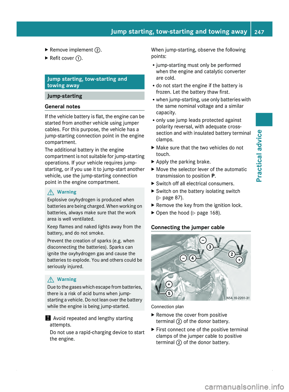
Connecting the jumper cable Connection plan
X
Remove the cover from positive
terminal 0047 of the donor battery.
X First connect one of the positive terminal
clamps of the jumper cable to positive
terminal 0047 of the donor battery. Jump starting, tow-starting and towing away
247
Practical advice Z
Page 250 of 292
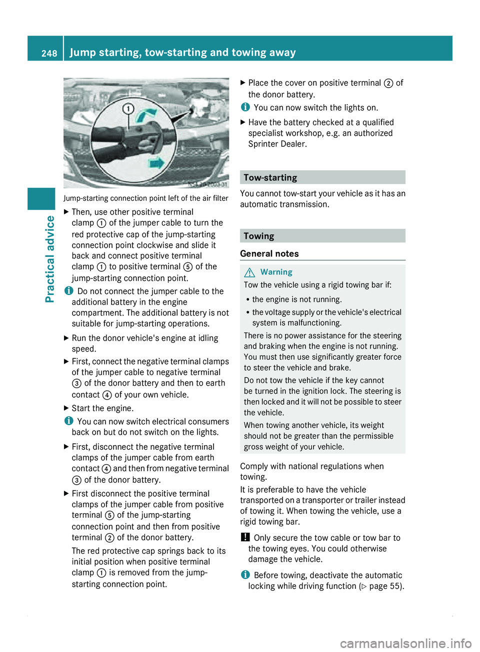
Jump-starting connection point left of the air filter
X
Then, use other positive terminal
clamp 0046 of the jumper cable to turn the
red protective cap of the jump-starting
connection point clockwise and slide it
back and connect positive terminal
clamp 0046 to positive terminal 0086 of the
jump-starting connection point.
i Do not connect the jumper cable to the
additional battery in the engine
compartment. The
additional
battery is not
suitable for jump-starting operations.
X Run the donor vehicle's engine at idling
speed.
X First, connect the negative terminal clamps
of the jumper cable to negative terminal
008A of the donor battery and then to earth
contact 0088 of your own vehicle.
X Start the engine.
i You can
now
switch electrical consumers
back on but do not switch on the lights.
X First, disconnect the negative terminal
clamps of the jumper cable from earth
contact 0088 and then
from negative terminal
008A of the donor battery.
X First disconnect the positive terminal
clamps of the jumper cable from positive
terminal 0086 of the jump-starting
connection point and then from positive
terminal 0047 of the donor battery.
The red protective cap springs back to its
initial position when positive terminal
clamp 0046 is removed from the jump-
starting connection point. X
Place the cover on positive terminal 0047 of
the donor battery.
i You can now switch the lights on.
X Have the battery checked at a qualified
specialist workshop, e.g. an authorized
Sprinter Dealer. Tow-starting
You cannot tow-start
your vehicle as it has an
automatic transmission. Towing
General notes G
Warning
Tow the vehicle using a rigid towing bar if:
R the engine is not running.
R the voltage supply
or the vehicle's electrical
system is malfunctioning.
There is no power assistance for the steering
and braking when the engine is not running.
You must then use significantly greater force
to steer the vehicle and brake.
Do not tow the vehicle if the key cannot
be turned in the ignition lock. The steering is
then locked and it will not be possible to steer
the vehicle.
When towing another vehicle, its weight
should not be greater than the permissible
gross weight of your vehicle.
Comply with national regulations when
towing.
It is preferable to have the vehicle
transported on a transporter or trailer instead
of towing it. When towing the vehicle, use a
rigid towing bar.
! Only secure the tow cable or tow bar to
the towing eyes. You could otherwise
damage the vehicle.
i Before towing, deactivate the automatic
locking while driving function (Y page 55). 248
Jump starting, tow-starting and towing away
Practical advice
Page 251 of 292
You could otherwise become locked out
when pushing or towing the vehicle.
! Do not exceed the towing speed of
31 mph (50 km/h). You could otherwise
damage the transmission.
X Turn the key to position 2
in the ignition
lock.
X For a towing distance of up to 30 miles
(50 km), move the selector lever to
position N. G
Warning
A propeller shaft could fall off as it is being
removed and injure
you. Secure the propeller
shaft before removal to prevent it from falling
down, e.g. with the aid of another person or
by tying the propeller shaft up.
X For a towing distance greater than
30 miles(50 km), remove the propeller
shafts to the driven axles.
! Always use new bolts when installing the
propeller shafts.
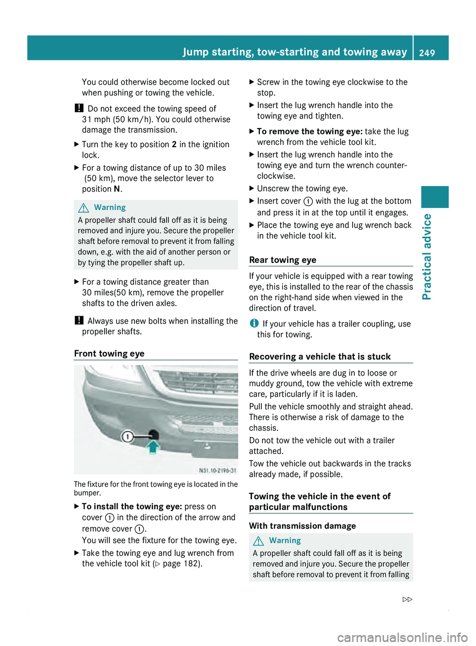
Front towing eye The fixture for the front towing eye is located in the
bumper.
X
To install the towing eye: press on
cover 0046 in the direction of the arrow and
remove cover 0046.
You will see the fixture for the towing eye.
X Take the towing eye and lug wrench from
the vehicle tool kit (Y page 182). X
Screw in the towing eye clockwise to the
stop.
X Insert the lug wrench handle into the
towing eye and tighten.
X To remove the towing eye: take the lug
wrench from the vehicle tool kit.
X Insert the lug wrench handle into the
towing eye and turn the wrench counter-
clockwise.
X Unscrew the towing eye.
X Insert cover 0046 with the lug at the bottom
and press it in at the top until it engages.
X Place the towing eye and lug wrench back
in the vehicle tool kit.
Rear towing eye If your vehicle is equipped with a rear towing
eye, this
is
installed to the rear of the chassis
on the right-hand side when viewed in the
direction of travel.
i If your vehicle has a trailer coupling, use
this for towing.
Recovering a vehicle that is stuck If the drive wheels are dug in to loose or
muddy ground, tow the vehicle with extreme
care, particularly if it is laden.
Pull the
vehicle
smoothly and straight ahead.
There is otherwise a risk of damage to the
chassis.
Do not tow the vehicle out with a trailer
attached.
Tow the vehicle out backwards in the tracks
already made, if possible.
Towing the vehicle in the event of
particular malfunctions With transmission damage
G
Warning
A propeller shaft could fall off as it is being
removed and injure
you. Secure the propeller
shaft before removal to prevent it from falling Jump starting, tow-starting and towing away
249
Practical advice
Z
Page 252 of 292
down, e.g. with the aid of another person or
by tying the propeller shaft up.
X Always remove the propeller shafts leading
to the driven axles.
! Always use new bolts when installing the
propeller shafts.
With front axle damage
X Turn the key to position 1 in the ignition
lock.
X Raise the front axle. G
Warning
A propeller shaft could fall off as it is being
removed and injure
you. Secure the propeller
shaft before removal to prevent it from falling
down, e.g. with the aid of another person or
by tying the propeller shaft up.
! The ignition must be switched off if the
vehicle is being towed with the front or rear
axle raised. Otherwise, ESP ®
may intervene
and damage the brake system.
With rear axle damage
X Turn the key to position 1 in the ignition
lock.
X Raise the rear axle.
Malfunction in the electrical system
If the battery is defective, the automatic
transmission will be locked in position P. To
shift the automatic transmission to
position N, you must provide power to the
vehicle's electrical system in the same way
as jump-starting ( Y page 247).
Have the vehicle
transported on a transporter
or trailer.
Transporting the vehicle The towing
eye can be used to pull the vehicle
onto a special transporter or trailer for
transportation.
! Only lash the
vehicle down by the wheels
or rims, not by vehicle parts such as axle or steering components. There is otherwise a
risk of damage to the vehicle.
X Move the selector lever of the automatic
transmission to position N.250
Jump starting, tow-starting and towing away
Practical advice
Page 279 of 292
for example an authorized Sprinter Dealer.
Otherwise, the vehicle parts may wear out
more quickly. This can invalidate the
general operating
permit
and the insurance
cover, and lead to the loss of the New
Vehicle Limited Warranty. Retrofitting electrical or electronic
equipment
Electrical and electronic equipment can
jeopardize the operational safety of the
vehicle. If equipment
of this kind is retrofitted,
it must be type-approved and bear the e
mark. The e mark may be obtained from the
equipment manufacturer or an authorized
testing center.
! Damage or consequential damage arising
from installing equipment that is not
approved for Sprinters is not covered by
the New Vehicle Limited Warranty.
If you wish to install telephones or two-way
radios in the vehicle, you must obtain formal
approval.
For operation of mobile phones and two-way
radios, We recommend connection to an
approved exterior antenna. This is the only
way to ensure optimum reception quality
inside the vehicle and to minimize mutual
interference between the vehicle electronics,
mobile phones and two-way radios. G
Warning
Excessive electromagnetic radiation may
constitute a health hazard to yourself and
others. Use of an exterior antenna gives
consideration to scientific discussion
surrounding the possible
health risk posed by
electromagnetic fields.
The exterior antenna should only be installed
at a qualified specialist workshop which has
the necessary specialist knowledge and tools
to carry out the work required. We
recommend that you use an authorized
Sprinter Dealer for this purpose. In particular,
work relevant to safety or on safety-related systems must be carried out at a qualified
specialist workshop.
The transmission output
of the mobile phone
or two-way radio must not exceed the
maximum transmission outputs listed. Frequency range Maximum
transmission
output (PEAK)
Short wave
(f < 50 MHz) 100 W
4 m waveband 30 W
2 m waveband 50 W
Trunked radio/Tetra 35 W
70 cm waveband 35 W
GSM 900/AMPS 10 W
GSM 1800 10 W
UMTS 10 W
!
If electrical or electronic equipment
which does not fulfill these conditions is
used in the vehicle, the vehicle's general
operating permit may be invalidated. Vehicle identification plates
Vehicle identification plates
The vehicle identification plate with the
vehicle identification number
(VIN), the paint
code, and the specifications for the
permissible weights is located on the base of
the driver's seat. Vehicle identification plates
277
Technical data Z
Page 287 of 292
vehicle's registration papers and on the type
plate of
the
trailer coupling, the trailer and the
vehicle identification plate ( Y page 277). In
the event that the data stated differs, the
lower value applies.
Make sure that you adhere to the weight
restrictions by having the weight checked at
a public weighbridge.
! The permissible gross combination
weight is less than the sum of the
permissible gross vehicle weight plus the
permissible trailer load. Exceeding the
permissible gross combination weight can
lead to damage to the drivetrain, to the
transmission or to the trailer tow hitch.
For this reason, applicable values for the
permissible gross vehicle weight or the
permissible trailer load are reduced
accordingly if either the vehicle or the
trailer is fully loaded. In this case, the trailer
or the vehicle may only be partially loaded. Operating data
285
Technical data Z