key battery MERCEDES-BENZ SPRINTER 2015 MY15 Operator’s Manual
[x] Cancel search | Manufacturer: MERCEDES-BENZ, Model Year: 2015, Model line: SPRINTER, Model: MERCEDES-BENZ SPRINTER 2015Pages: 334, PDF Size: 5.94 MB
Page 7 of 334
Transmission oil change ................3
24
Automatic transmission emer-
gency mode ....................................... 145
AUX port ............................................. 237
Auxiliary heating
Activating/deactivating heater
booster mode ................................ 130
Adjusting ....................................... 194
Conditions for switching on ........... 123
Heating time .................................. 123
Important safety notes .................. 122
Operating with the button (control
panel) ............................................ 123
Operation with the remote con-
trol ................................................. 125
Operation with the timer ................ 127
Problem (malfunction) ................... 132
Selecting a switch-on time ............. 124
Setting the switch-on time ............. 125
see Auxiliary heating
Axle load, permissible (trailer tow-
ing) ...................................................... 330 B
Backup lamps Replacing bulbs ............................ .103
Backup lamps (Chassis Cab)
Replacing bulbs ............................ .104
BAS (Brake Assist System)
Display message ............................ 205
Function/notes ................................ 59
Indicator lamp ................................ 218
Basic settings
see Settings
Battery
Isolating switch .............................. 137
Replacing (SmartKey) ..................... .69
Battery (SmartKey)
Checking .......................................... 68
Important safety notes .................... 68
Replacing ......................................... 69
Battery (vehicle)
Care ............................................... 264
Charge indicator lamp ................... 222
Charging ........................................ 263
Disconnecting and connecting
(driver's footwell) ........................... 260 Disconnecting and connecting
(engine compartment) ................... 262
Display message ............................ 216
Important safety notes .................. 258
Installing/removing (driver's foot-
well )............................................... 262
Installing/removing (engine com-
partment) ....................................... 263
Jump starting ................................. 276
Location ......................................... 260
Removing/installing the floor cov-
ering (driver's footwell) .................. 260
Before driving off
Important safety notes .................. 138
Belt
see Seat belts
Bleeding the fuel system .................. 141
Blind Spot Assist
Activating/deactivating ......... 165, 194
Notes/function .............................. 163
Trailer towing ................................. 165
BlueTEC exhaust gas aftertreat-
ment
Notes ............................................... 25
Bottle holder
see Cup holder
Brake Assist
see BAS (Brake Assist System)
Brake Assist System
see BAS (Brake Assist System)
Brake fluid
Checking the level ......................... 254
Display message ............................ 206
Notes ............................................. 324
Warning lamp ................................. 219
Brake force distribution, elec-
tronic
see EBD (electronic brake force
distribution)
Brake lamps
Replacing bulb s............................. 103
Brake lamps (Chassis Cab)
Replacing bulb s............................. 104
Brake linings
Display message ............................ 205
Indicator lamp ................................ 222
Brake system
Malfunction .................................... 205 Index
5
Page 19 of 334
Side windows
Cleaning ......................................... 267
Hinged side windows ....................... 78
Important safety information ........... 78
Opening/closing .............................. 78
Overview .......................................... 78
Problem (malfunction) ..................... 79
Resetting ......................................... 79
Sliding door
Child-proof locks .............................. 56
Cleaning ......................................... 269
Closing assist ................................... 73
Important safety notes .................... 72
Opening/closing .............................. 72
Opening/closing from the inside ..... 73
Opening/closing from the out-
side .................................................. 73
SmartKey
Changing the battery ....................... 69
Changing the locking system set-
tings ............................................... 194
Checking the battery ....................... 68
Display message ............................2 17
Door central locking/unlocking ....... 66
Important safety notes .................... 66
Loss ................................................. 70
Problem (malfunction) ..................... 70
SmartKey positions (ignition lock) .. 138
Snow chains ...................................... 287
Sockets .............................................. 236
Spare wheel
General notes ................................ 312
Important safety notes .................. 312
Removing/mounting ..................... .313
Special seat belt retractor .................. 52
Specialist workshop ............................ 25
Speed, controlling
see Cruise control
Speedometer
Digital (vehicles with steering
wheel buttons) ............................... 191
Digital (vehicles without steering
wheel buttons) ............................... 182
Selecting display unit (vehicles
with steering- wheel buttons) ....... .190
see Instrument cluster Sprinter Dealer
see Qualified specialist workshop
Standing lamps
Replacing bulbs ............................ .100
Replacing bulbs (rear) .................... 103
Standing lamps (Chassis Cab)
Replacing bulbs (rear) .................... 104
Start-off assist
Display message ............................ 205
Starting (engine) ................................ 139
Station
see Radio
Steering wheel
Adjusting ......................................... 88
Button overview ............................... 37
Cleaning ......................................... 270
Step
see Electrical step
Stickers
General safety notes ........................ 22
Stowage spaces
see Stowage spaces and stowagecompartments
Stowage spaces and stowage com-
partments
Eyeglasses compartment .............. .231
Glove box ....................................... 230
Important safety notes .................. 230
Paper holder .................................. 233
Stowage compartment above the
windshield ..................................... 232
Stowage compartment in the cen-
ter console ..................................... 232
Stowage compartment in the
dashboard ...................................... 231
Stowage space above the head-
liner ............................................... 232
Stowage space under the rear
bench seat ..................................... 233
Stowage space under the twin co-
driver's sea t................................... 232
Summer tires ..................................... 286
Switch unit
see Control panel
Switching off the alarm (ATA) ............ 61
Switching the heater booster func-
tion on/off ......................................... 130 Index
17
Page 22 of 334
Trailer
Brake force booster malfunction ... 219
Trailer coupling
see Towing a trailer
Trailer loads and drawbar nose-
weights .............................................. .177
Trailer towing
Blind Spot Assist ............................ 165
PARKTRONIC ................................. 170
Permissible trailer loads and
drawbar noseweights ..................... 177
Transmission
see Automatic transmission
Transmission oil ................................ 324
Transport
Loading guidelines ......................... 240
Vehicle .......................................... .280
Transport by rail ................................ 154
Transportation
Rail ................................................ 154
Transporting
Load distribution ............................ 242
Securing a load .............................. 242
Trim pieces (cleaning instruc-
tions) ................................................. .270
Trip computer (on-board com-
puter) ................................................. .195
Trip meter
see Trip odometer
Trip odometer
Display (vehicles with steering
wheel buttons) ............................... 187
Display (vehicles without steeringwheel buttons) ............................... 182
Resetting ....................................... 181
see Trip computer (on-board computer)
Turn signals
Replacing bulbs (front) ................... 102
Replacing bulbs (rear) .................... 103
Switching on/off .............................. 94
Turn signals (Chassis Cab)
Replacing bulbs (rear) .................... 104
Twin co-driver's seat
Folding table .................................. 234
Stowage compartment .................. 232
Two-way radios
Type approval/frequency .............. 316 TWR (Tongue Weight Rating) (defi-
nition)
................................................. 305 U
Unlocking From inside the vehicle (central
unlocking button) ............................ .71
USB port .............................................2 38 V
Vehicle Data acquisition ............................... 29
Display message ............................ 216
Electronics ..................................... 316
Equipment ....................................... 22
Individual settings (vehicles with
steering wheel buttons) ................. 188
Limited Warranty ............................ .22
Loading .......................................... 295
Locking (SmartKey) .......................... 66
Lowering ........................................ 310
Maintenance .................................... 28
Parking for a long period ................ 151
Pulling away ................................... 140
Raising ........................................... 307
Registration ............................... 25, 28
Reporting problems ......................... 28
Securing from rolling away ............ 149
Towing away .................................. 277
Transporting .................................. 280
Unlocking (SmartKey )...................... 66
Vehicle battery
see Battery (vehicle)
Vehicle bodies
Body/equipment mounting direc-
tives for trucks ................................. 26
Vehicle data ....................................... 327
Vehicle identification number .......... 316
Vehicle identification plate .............. 316
Vehicle tool kit .................................. 274
Vents
see Air vents
Voltage supply
Fuses ............................................. 280 20
Index
Page 63 of 334
X
Position both handles 0043horizontally.
Make sure that the locks 0087are inside in
front of the window frame.
The window is locked.
X Replace locking pins 0044at the latest before
starting on a new journey.
You can obtain information on this at any
qualified specialist workshop.
In an emergency, or after an accident, the
vehicle occupants can exit the vehicle
through the emergency exit window.
Observe the following notes to make sure that
the emergency exit window can be used
safely in the event of an emergency:
R Before beginning a journey, inform the vehi-
cle occupants of the emergency exit win-
dow and explain how to use it. Make sure to
explicitly point out the risks described here.
R Only vehicle occupants who know how to
use the emergency exit window are permit-
ted to sit next to it.
R Access to the emergency exit window must
remain unobstructed. Do not place any
large or heavy objects on or in front of the
seats next to the emergency exit window.
R The window handles must not be used as
hooks, e.g. to hang up light objects, bags or
items of clothing.
R When exiting the vehicle through the emer-
gency exit window, pay attention to the
vehicle height and the local conditions. Par- ticularly children and smaller adults may
require assistance when exiting the vehi-
cle. Theft deterrent locking system
Immobilizer
X To activate: remove the key from the igni-
tion lock.
X To deactivate: turn the key to position 2in
the ignition lock.
The immobilizer prevents your vehicle from
being started without the correct key. Always take the key with you and lock the
vehicle when leaving the vehicle. If you leave
the key in the vehicle, anyone can start the
engine.
i The immobilizer is always deactivated
when you start the engine.
In the event that the engine cannot be star- ted when the starter battery is fully
charged, the immobilizer may be faulty.
Contact an authorized Sprinter dealer or
call 1-877-762-8267 (in USA) or
1-800-387-0100 (in Canada). ATA (Anti-Theft Alarm system)
X To arm: close all doors.
X Lock the vehicle with the key.
The indicator lamp in the central locking
button (Y page 71) flashes.
X To deactivate: unlock the vehicle with the
key.
The indicator lamp in the central locking
button (Y page 71) goes out.
i Cargo Van and Passenger Van only:
Unless you open a door within 40 seconds
after unlocking the vehicle:
R the vehicle will be locked again
R the anti-theft alarm system will be armed
again
If the alarm system is armed, a visual and
audible alarm is triggered by the following:
R Unlocking the vehicle from inside
R Opening a door
R Opening the hood
i The alarm is not switched off, even if you
immediately close the open door that has
triggered it, for example.
X To stop the alarm: press the0036button
on the remote control.
or
X Insert the key into the ignition lock.
The alarm stops. Theft deterrent locking system
61Safety Z
Page 69 of 334
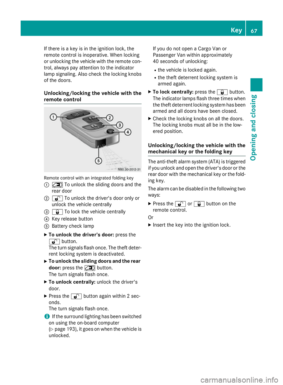
If there is a key is in the ignition lock, the
remote control is inoperative. When locking
or unlocking the vehicle with the remote con- trol, always pay attention to the indicator
lamp signaling. Also check the locking knobs
of the doors.
Unlocking/locking the vehicle with the
remote control Remote control with an integrated folding key
0043 0042 To unlock the sliding doors and the
rear door
0044 0036 To unlock the driver's door only or
unlock the vehicle centrally
0087 0037 To lock the vehicle centrally
0085 Key release button
0083 Battery check lamp
X To unlock the driver's door: press the
0036 button.
The turn signals flash once. The theft deter-
rent locking system is deactivated.
X To unlock the sliding doors and the rear
door: press the 0042button.
The turn signals flash once.
X To unlock centrally: unlock the driver's
door.
X Press the 0036button again within 2 sec-
onds.
The turn signals flash once.
i If the surround lighting has been switched
on using the on-board computer
(Y page 193), it goes on when the vehicle is
unlocked. If you do not open a Cargo Van or
Passenger Van within approximately
40 seconds of unlocking:
R the vehicle is locked again.
R the theft deterrent locking system is
armed again.
X To lock centrally: press the0037button.
The indicator lamps flash three times when
the theft deterrent locking system has been armed and all doors have been closed.
X Check the locking knobs on all the doors.
The locking knobs must all be in the low-
ered position.
Unlocking/locking the vehicle with the
mechanical key or the folding key The anti-theft alarm system (ATA) is triggered
if you unlock and open the driver's door or the
rear door with the mechanical key or the fold-
ing key.
The alarm can be disabled in the following two ways:
X Press the 0036or0037 button on the
remote control.
Or
X Insert the key into the ignition lock. Key
67Opening and closing Z
Page 70 of 334
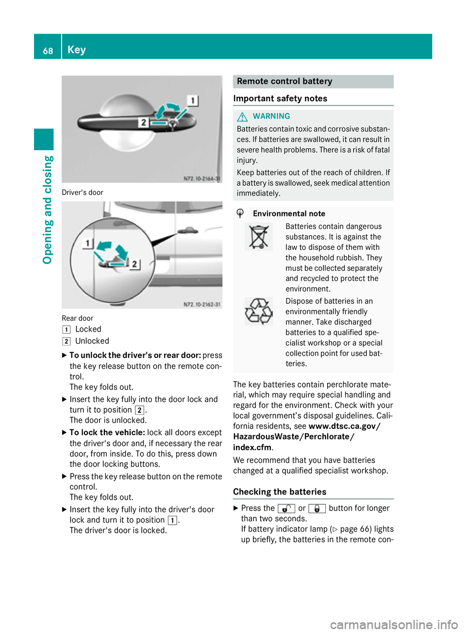
Driver's door
Rear door
0047
Locked
0048 Unlocked
X To unlock the driver's or rear door: press
the key release button on the remote con-
trol.
The key folds out.
X Insert the key fully into the door lock and
turn it to position 0048.
The door is unlocked.
X To lock the vehicle: lock all doors except
the driver's door and, if necessary the rear
door, from inside. To do this, press down
the door locking buttons.
X Press the key release button on the remote
control.
The key folds out.
X Insert the key fully into the driver's door
lock and turn it to position 0047.
The driver's door is locked. Remote control battery
Important safety notes G
WARNING
Batteries contain toxic and corrosive substan- ces. If batteries are swallowed, it can result in
severe health problems. There is a risk of fatal injury.
Keep batteries out of the reach of children. If
a battery is swallowed, seek medical attention immediately. H
Environmental note Batteries contain dangerous
substances. It is against the
law to dispose of them with
the household rubbish. They
must be collected separately
and recycled to protect the
environment. Dispose of batteries in an
environmentally friendly
manner. Take discharged
batteries to a qualified spe-
cialist workshop or a special
collection point for used bat-
teries.
The key batteries contain perchlorate mate-
rial, which may require special handling and
regard for the environment. Check with your
local government’s disposal guidelines. Cali-
fornia residents, see www.dtsc.ca.gov/
HazardousWaste/Perchlorate/
index.cfm.
We recommend that you have batteries
changed at a qualified specialist workshop.
Checking the batteries X
Press the 0036or0037 button for longer
than two seconds.
If battery indicator lamp (Y page 66) lights
up briefly, the batteries in the remote con- 68
KeyOpening and closing
Page 71 of 334
trol still have sufficient charge. Otherwise,
change the batteries immediately.
i If the remote control is checked within the
signal reception range of the vehicle, press- ing the 0037or0036 button:
R lock or
R unlock the vehicle
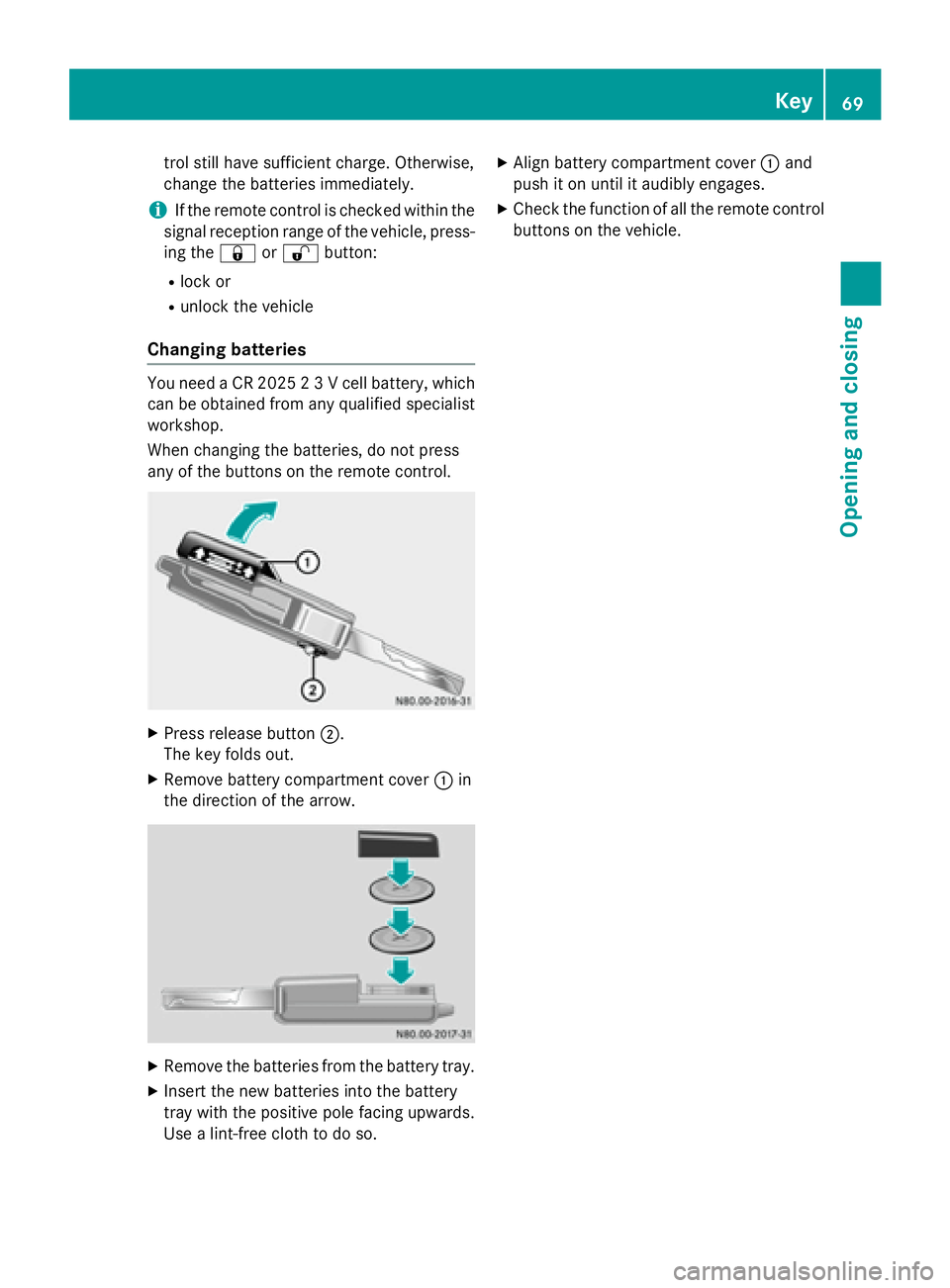
Changing batteries You need a CR 2025 2 3 V cell battery, which
can be obtained from any qualified specialist
workshop.
When changing the batteries, do not press
any of the buttons on the remote control. X
Press release button 0044.
The key folds out.
X Remove battery compartment cover 0043in
the direction of the arrow. X
Remove the batteries from the battery tray.
X Insert the new batteries into the battery
tray with the positive pole facing upwards.
Use a lint-free cloth to do so. X
Align battery compartment cover 0043and
push it on until it audibly engages.
X Check the function of all the remote control
buttons on the vehicle. Key
69Opening and closing Z
Page 72 of 334
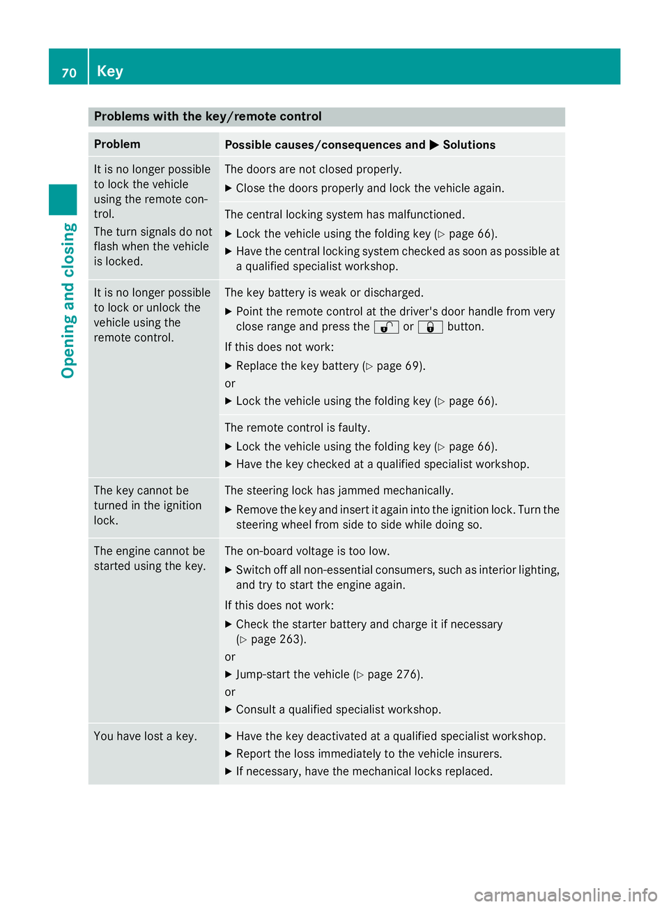
Problems with the key/remote control
Problem
Possible causes/consequences and
0050
0050Solutions It is no longer possible
to lock the vehicle
using the remote con-
trol.
The turn signals do not
flash when the vehicle
is locked. The doors are not closed properly.
X Close the doors properly and lock the vehicle again. The central locking system has malfunctioned.
X Lock the vehicle using the folding key (Y page 66).
X Have the central locking system checked as soon as possible at
a qualified specialist workshop. It is no longer possible
to lock or unlock the
vehicle using the
remote control. The key battery is weak or discharged.
X Point the remote control at the driver's door handle from very
close range and press the 0036or0037 button.
If this does not work:
X Replace the key battery (Y page 69).
or
X Lock the vehicle using the folding key (Y page 66). The remote control is faulty.
X Lock the vehicle using the folding key (Y page 66).
X Have the key checked at a qualified specialist workshop. The key cannot be
turned in the ignition
lock. The steering lock has jammed mechanically.
X Remove the key and insert it again into the ignition lock. Turn the
steering wheel from side to side while doing so. The engine cannot be
started using the key. The on-board voltage is too low.
X Switch off all non-essential consumers, such as interior lighting,
and try to start the engine again.
If this does not work: X Check the starter battery and charge it if necessary
(Y page 263).
or
X Jump-start the vehicle (Y page 276).
or
X Consult a qualified specialist workshop. You have lost a key. X
Have the key deactivated at a qualified specialist workshop.
X Report the loss immediately to the vehicle insurers.
X If necessary, have the mechanical locks replaced. 70
KeyOpening and closing
Page 90 of 334
X
Make sure that the key is in position 1or 2
in the ignition lock.
X To switch on: press the0072button
repeatedly until the desired heating level
has been set.
X To switch off: press the0072button
repeatedly until all indicator lamps go out.
If the indicator lamps of the current heating
level in the 0072button flash, the seat heat-
ing has switched off automatically. In this
case, too many electrical consumers are
switched on or the battery charge is not suf-
ficient. The seat heating will automatically
switch back to the current heating level when
enough on-board voltage is available again. Steering wheel
G
WARNING
You could lose control of your vehicle if you do the following while driving:
R adjust the driver's seat, head restraint,
steering wheel or mirrors
R fasten the seat belt
There is a risk of an accident.
Adjust the driver's seat, head restraint, steer-
ing wheel and mirror and fasten your seat belt before starting the engine. G
WARNING
If the steering wheel is unlocked while the
vehicle is in motion, it could change position
unexpectedly. This could cause you to lose
control of the vehicle. There is a risk of an
accident.
Before starting off, make sure the steering
wheel is locked. Never unlock the steering
wheel while the vehicle is in motion. G
WARNING
Children could injure themselves if they
adjust the steering wheel. There is a risk of
injury. When leaving the vehicle, always take the
SmartKey with you and lock the vehicle. Never
leave children unsupervised in the vehicle.
The steering wheel can still be adjusted if the
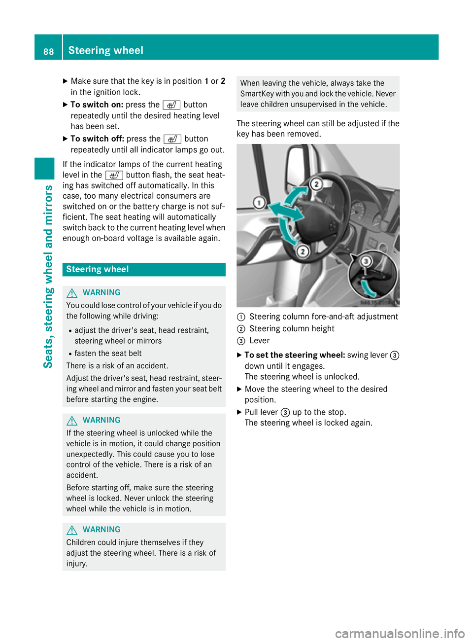
key has been removed. 0043
Steering column fore-and-aft adjustment
0044 Steering column height
0087 Lever
X To set the steering wheel: swing lever0087
down until it engages.
The steering wheel is unlocked.
X Move the steering wheel to the desired
position.
X Pull lever 0087up to the stop.
The steering wheel is locked again. 88
Steering wheelSeats, steering wheel and mirrors
Page 101 of 334
Motion detector
G
WARNING
The motion detector sends the invisible infra- red radiation emitted by LEDs (light emitting
diodes).
These LEDs are classified as class 1M lasers
and can damage the retina if you:
R look directly into the unfiltered laser beam
of the motion detector for an extended
period
R look directly into the laser beam of the
motion detector using optical instruments,
e.g. eyeglasses or a magnifying glass.
There is a risk of injury.
Never look directly into the motion detector.
The cargo compartment lighting is also
switched on by the motion detector in the
cargo compartment of Cargo Vans equipped
with this feature.
If the motion detector detects a movement in the cargo compartment when the vehicle is
stationary, the cargo compartment lighting
switches on for approximately two minutes.
The cargo compartment lighting can be
switched on by the motion detector within
four seconds if:
R the rear interior light switch (Y page 98) is
set to automatic control.
R the vehicle is stationary, the parking brake
is applied and the brake pedal is not being
depressed
Or
R the selector lever is in position Pon vehi-
cles with automatic transmission and the
brake pedal is not being depressed and
R the vehicle has not been locked from the
outside using the key
The motion detector switches off automati-
cally if no change is detected in the vehicle for
several hours, e.g. if a door is opened, if the
ignition key is turned, etc. This prevents the
battery from becoming discharged. Changing bulbs
Important safety notes
G
DANGER
Xenon bulbs carry a high voltage. You can get an electric shock if you remove the cover of
the Xenon bulb and touch the electrical con-
tacts. There is a risk of fatal injury.
Never touch the parts or the electrical con-
tacts of the Xenon bulb. Always have work on
the Xenon bulbs carried out at a qualified spe-
cialist workshop. G
WARNING
Bulbs, lamps and connectors can get very hot when operating. If you change a bulb, you
could burn yourself on these components.
There is a risk of injury.
Allow these components to cool down before changing a bulb.
! Make sure the bulbs are always securely
installed.
If your vehicle is equipped with Bi-Xenon
bulbs, you can recognize this by the following: the cone of light from the Xenon bulbs moves
from the top to the bottom and back again
when you start the engine. For this to be
observed, the low-beam headlamps must be
switched on before starting the engine.
The bulbs and lamps are an essential compo- nent of vehicle safety. You must therefore
make sure that these function correctly at all
times. Have the headlamp setting checked
regularly.
R Always switch off the vehicle's lighting sys-
tem before changing a bulb.
This will prevent a short circuit.
R Do not touch the glass tube of new bulbs
with your bare hands. Always use a clean,
lint-free cloth or only touch the base of the bulb when installing.
Even minor contamination can burn into
the glass surface and reduce the service life
of the bulbs. Changing bulbs
99Lights and windshield wipers Z