remote control MERCEDES-BENZ SPRINTER 2015 MY15 Operator’s Manual
[x] Cancel search | Manufacturer: MERCEDES-BENZ, Model Year: 2015, Model line: SPRINTER, Model: MERCEDES-BENZ SPRINTER 2015Pages: 334, PDF Size: 5.94 MB
Page 7 of 334
Transmission oil change ................3
24
Automatic transmission emer-
gency mode ....................................... 145
AUX port ............................................. 237
Auxiliary heating
Activating/deactivating heater
booster mode ................................ 130
Adjusting ....................................... 194
Conditions for switching on ........... 123
Heating time .................................. 123
Important safety notes .................. 122
Operating with the button (control
panel) ............................................ 123
Operation with the remote con-
trol ................................................. 125
Operation with the timer ................ 127
Problem (malfunction) ................... 132
Selecting a switch-on time ............. 124
Setting the switch-on time ............. 125
see Auxiliary heating
Axle load, permissible (trailer tow-
ing) ...................................................... 330 B
Backup lamps Replacing bulbs ............................ .103
Backup lamps (Chassis Cab)
Replacing bulbs ............................ .104
BAS (Brake Assist System)
Display message ............................ 205
Function/notes ................................ 59
Indicator lamp ................................ 218
Basic settings
see Settings
Battery
Isolating switch .............................. 137
Replacing (SmartKey) ..................... .69
Battery (SmartKey)
Checking .......................................... 68
Important safety notes .................... 68
Replacing ......................................... 69
Battery (vehicle)
Care ............................................... 264
Charge indicator lamp ................... 222
Charging ........................................ 263
Disconnecting and connecting
(driver's footwell) ........................... 260 Disconnecting and connecting
(engine compartment) ................... 262
Display message ............................ 216
Important safety notes .................. 258
Installing/removing (driver's foot-
well )............................................... 262
Installing/removing (engine com-
partment) ....................................... 263
Jump starting ................................. 276
Location ......................................... 260
Removing/installing the floor cov-
ering (driver's footwell) .................. 260
Before driving off
Important safety notes .................. 138
Belt
see Seat belts
Bleeding the fuel system .................. 141
Blind Spot Assist
Activating/deactivating ......... 165, 194
Notes/function .............................. 163
Trailer towing ................................. 165
BlueTEC exhaust gas aftertreat-
ment
Notes ............................................... 25
Bottle holder
see Cup holder
Brake Assist
see BAS (Brake Assist System)
Brake Assist System
see BAS (Brake Assist System)
Brake fluid
Checking the level ......................... 254
Display message ............................ 206
Notes ............................................. 324
Warning lamp ................................. 219
Brake force distribution, elec-
tronic
see EBD (electronic brake force
distribution)
Brake lamps
Replacing bulb s............................. 103
Brake lamps (Chassis Cab)
Replacing bulb s............................. 104
Brake linings
Display message ............................ 205
Indicator lamp ................................ 222
Brake system
Malfunction .................................... 205 Index
5
Page 18 of 334
Releasing the parking lock man-
ually (automatic transmission)
........ 145
Remote control
Changing the operating duration
(auxiliary heating) .......................... 126
Replacing the battery (auxiliary
heating ) ........................................ 130
Switching on/off (auxiliary heat-
ing) ................................................ 126
Synchronizing (auxiliary heating) ... 126
Replacing bulbs
Important safety notes .................... 99
Replacing the battery (auxiliary
heating remote control) .................... 130
Restraint system
Introduction ..................................... 42
Warning lamp (function) .......... 42, 222
Reverse warning feature .................. 140
Roof carrier
Maximum payloa d.......................... 328
Notes ............................................. 245
Roof load (roof carrier) ..................... 328S
Safety Child restraint systems .................... 52
Children in the vehicle ..................... 51
Safety system
see Driving safety systems
Seat belts
Adjusting the height ......................... 45
Cleaning ......................................... 271
Correct usage .................................. 45
Display message ............................ 207
Fastening ......................................... 45
Important safety guidelines ............. 44
Introduction ..................................... 43
Releasing ......................................... 46
Warning lamp ................................. 227
Warning lamp (function) ................... 46
Seat heating ......................................... 87
Seats
Adjusting lumbar support ................ 83
Adjusting the co-driver's sea t.......... 83
Adjusting the head restraint ............ 86
Armrest ............................................ 87
Cleaning the cover ......................... 271 Correct driver's seat position ........... 82
Folding seat ..................................... 85
Important safety notes .................... 82
Rear bench seat ............................... 85
Seat heating .................................... 87
Setting the driver's seat ................... 83
Swivel seat ....................................... 84
Twin co-driver's seat ........................ 85
Securing loads
Important safety notes .................. 242
Selector lever
Cleaning ......................................... 270
Sensors (cleaning instructions) ....... 268
Service center
see Qualified specialist workshop
Service interval display
Calling up the service due date ...... 258
Exceeding a service due date ........ 258
Notes ............................................. 257
Service due date (automatic dis-
play) ............................................... 257
Service products
Brake fluid ..................................... 324
Coolant (engine) ............................ 325
Diesel ............................................ 318
Diesel Exhaust Fluid (DEF) ............. 320
Engine oil ....................................... 322
Fuel ................................................ 318
Important safety notes .................. 318
Power steering fluid ....................... 324
Refrigerant ..................................... 326
Transmission oil ............................. 324
Washer fluid ................................... 326
Setting the air distribution ............... 117
Setting the airflow ............................ 118
Setting the clock
Vehicles with steering wheel but-
tons ............................................... 191
Vehicles without steering wheel
buttons .......................................... 183
Settings
Resetting all (vehicles with steer-
ing wheel buttons) ......................... 188
Resetting submenus (vehicles
with steering wheel buttons) ......... 189
Short journeys (diesel particle fil-
ter) ...................................................... 153 16
Index
Page 63 of 334
X
Position both handles 0043horizontally.
Make sure that the locks 0087are inside in
front of the window frame.
The window is locked.
X Replace locking pins 0044at the latest before
starting on a new journey.
You can obtain information on this at any
qualified specialist workshop.
In an emergency, or after an accident, the
vehicle occupants can exit the vehicle
through the emergency exit window.
Observe the following notes to make sure that
the emergency exit window can be used
safely in the event of an emergency:
R Before beginning a journey, inform the vehi-
cle occupants of the emergency exit win-
dow and explain how to use it. Make sure to
explicitly point out the risks described here.
R Only vehicle occupants who know how to
use the emergency exit window are permit-
ted to sit next to it.
R Access to the emergency exit window must
remain unobstructed. Do not place any
large or heavy objects on or in front of the
seats next to the emergency exit window.
R The window handles must not be used as
hooks, e.g. to hang up light objects, bags or
items of clothing.
R When exiting the vehicle through the emer-
gency exit window, pay attention to the
vehicle height and the local conditions. Par- ticularly children and smaller adults may
require assistance when exiting the vehi-
cle. Theft deterrent locking system
Immobilizer
X To activate: remove the key from the igni-
tion lock.
X To deactivate: turn the key to position 2in
the ignition lock.
The immobilizer prevents your vehicle from
being started without the correct key. Always take the key with you and lock the
vehicle when leaving the vehicle. If you leave
the key in the vehicle, anyone can start the
engine.
i The immobilizer is always deactivated
when you start the engine.
In the event that the engine cannot be star- ted when the starter battery is fully
charged, the immobilizer may be faulty.
Contact an authorized Sprinter dealer or
call 1-877-762-8267 (in USA) or
1-800-387-0100 (in Canada). ATA (Anti-Theft Alarm system)
X To arm: close all doors.
X Lock the vehicle with the key.
The indicator lamp in the central locking
button (Y page 71) flashes.
X To deactivate: unlock the vehicle with the
key.
The indicator lamp in the central locking
button (Y page 71) goes out.
i Cargo Van and Passenger Van only:
Unless you open a door within 40 seconds
after unlocking the vehicle:
R the vehicle will be locked again
R the anti-theft alarm system will be armed
again
If the alarm system is armed, a visual and
audible alarm is triggered by the following:
R Unlocking the vehicle from inside
R Opening a door
R Opening the hood
i The alarm is not switched off, even if you
immediately close the open door that has
triggered it, for example.
X To stop the alarm: press the0036button
on the remote control.
or
X Insert the key into the ignition lock.
The alarm stops. Theft deterrent locking system
61Safety Z
Page 68 of 334
Useful information
This Operator's Manual describes all models
as well as standard and optional equipment of your vehicle that were available at the time of going to print. Country-specific variations are
possible. Note that your vehicle may not be
equipped with all of the described functions.
This also applies to systems and functions
relevant to safety.
Read the information on qualified specialist
workshops (Y page 25). Key
Important safety notes
G
WARNING
Activate the child-proof door locks if children are traveling in the vehicle. The children could
otherwise open the doors while the vehicle is
in motion, injuring themselves and others. G
WARNING
Do not leave children unsupervised in the
vehicle, even if they are secured in a child
restraint system. Children could otherwise
injure themselves on parts of the vehicle.
They could be severely or even fatally injured by prolonged exposure to intense heat or
cold.
If children open a door, they could:
R injure other people
R get out of the vehicle and thereby injure
themselves or be injured by a passing vehi-
cle
R severely injure themselves by falling down,
in particular due to the vehicle height
Always take the key with you when leaving the
vehicle, even if you are only leaving for a short time. G
WARNING
If you attach heavy or large objects to the
SmartKey, the SmartKey could be uninten- tionally turned in the ignition lock. This could
cause the engine to be switched off. There is a risk of an accident.
Do not attach any heavy or large objects to the
SmartKey. Remove any bulky key rings before
inserting the SmartKey into the ignition lock.
Do not keep the key with remote control:
R with electronic devices, e.g. a mobile
phone or another key with remote control
R with metallic objects, e.g. coins or metal
foil
R in metallic objects, e.g. metal cases
This can affect the key's functionality. Key functions of the remote control
General notes The vehicle is equipped with either 2 or
4 remote controls with a folding key, or 4
mechanical keys. In this Operator's Manual,
both the mechanical keys and the keys with
remote control are referred to as keys. The
remote control key has a range of up to 32 ft (10 m). Use the remote control of the key only
when in immediate proximity of the vehicle.
This prevents theft.
Remote controls that are not included in the
scope of delivery for the vehicle must be pro- grammed before use. Further information can
be obtained at any authorized Sprinter
Dealer.
The key's remote control locks/unlocks the
driver's door and/or the following centrally if the factory settings have not been changed:
R the driver's and the co-driver's door
R the sliding doors
R the rear doors
i If the driver's or co-driver's door is not
closed, the corresponding door is not
locked. If a sliding door or a rear door is not
closed properly, none of the rear doors are
locked. 66
KeyOpening and closing
Page 69 of 334
If there is a key is in the ignition lock, the
remote control is inoperative. When locking
or unlocking the vehicle with the remote con- trol, always pay attention to the indicator
lamp signaling. Also check the locking knobs
of the doors.
Unlocking/locking the vehicle with the
remote control Remote control with an integrated folding key
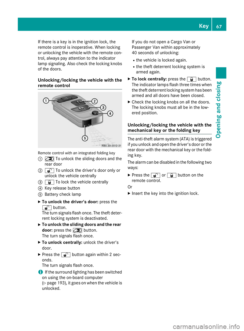
0043 0042 To unlock the sliding doors and the
rear door
0044 0036 To unlock the driver's door only or
unlock the vehicle centrally
0087 0037 To lock the vehicle centrally
0085 Key release button
0083 Battery check lamp
X To unlock the driver's door: press the
0036 button.
The turn signals flash once. The theft deter-
rent locking system is deactivated.
X To unlock the sliding doors and the rear
door: press the 0042button.
The turn signals flash once.
X To unlock centrally: unlock the driver's
door.
X Press the 0036button again within 2 sec-
onds.
The turn signals flash once.
i If the surround lighting has been switched
on using the on-board computer
(Y page 193), it goes on when the vehicle is
unlocked. If you do not open a Cargo Van or
Passenger Van within approximately
40 seconds of unlocking:
R the vehicle is locked again.
R the theft deterrent locking system is
armed again.
X To lock centrally: press the0037button.
The indicator lamps flash three times when
the theft deterrent locking system has been armed and all doors have been closed.
X Check the locking knobs on all the doors.
The locking knobs must all be in the low-
ered position.
Unlocking/locking the vehicle with the
mechanical key or the folding key The anti-theft alarm system (ATA) is triggered
if you unlock and open the driver's door or the
rear door with the mechanical key or the fold-
ing key.
The alarm can be disabled in the following two ways:
X Press the 0036or0037 button on the
remote control.
Or
X Insert the key into the ignition lock. Key
67Opening and closing Z
Page 70 of 334
Driver's door
Rear door
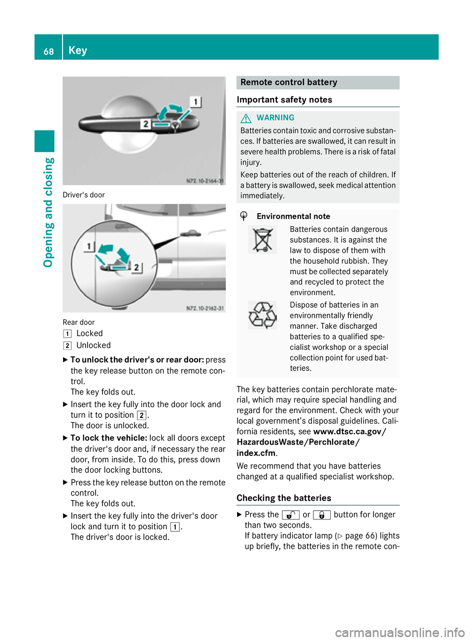
0047
Locked
0048 Unlocked
X To unlock the driver's or rear door: press
the key release button on the remote con-
trol.
The key folds out.
X Insert the key fully into the door lock and
turn it to position 0048.
The door is unlocked.
X To lock the vehicle: lock all doors except
the driver's door and, if necessary the rear
door, from inside. To do this, press down
the door locking buttons.
X Press the key release button on the remote
control.
The key folds out.
X Insert the key fully into the driver's door
lock and turn it to position 0047.
The driver's door is locked. Remote control battery
Important safety notes G
WARNING
Batteries contain toxic and corrosive substan- ces. If batteries are swallowed, it can result in
severe health problems. There is a risk of fatal injury.
Keep batteries out of the reach of children. If
a battery is swallowed, seek medical attention immediately. H
Environmental note Batteries contain dangerous
substances. It is against the
law to dispose of them with
the household rubbish. They
must be collected separately
and recycled to protect the
environment. Dispose of batteries in an
environmentally friendly
manner. Take discharged
batteries to a qualified spe-
cialist workshop or a special
collection point for used bat-
teries.
The key batteries contain perchlorate mate-
rial, which may require special handling and
regard for the environment. Check with your
local government’s disposal guidelines. Cali-
fornia residents, see www.dtsc.ca.gov/
HazardousWaste/Perchlorate/
index.cfm.
We recommend that you have batteries
changed at a qualified specialist workshop.
Checking the batteries X
Press the 0036or0037 button for longer
than two seconds.
If battery indicator lamp (Y page 66) lights
up briefly, the batteries in the remote con- 68
KeyOpening and closing
Page 71 of 334
trol still have sufficient charge. Otherwise,
change the batteries immediately.
i If the remote control is checked within the
signal reception range of the vehicle, press- ing the 0037or0036 button:
R lock or
R unlock the vehicle
Changing batteries You need a CR 2025 2 3 V cell battery, which
can be obtained from any qualified specialist
workshop.
When changing the batteries, do not press
any of the buttons on the remote control. X
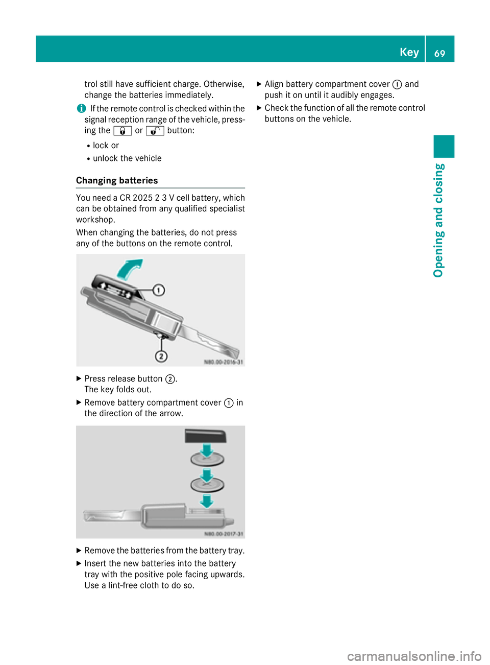
Press release button 0044.
The key folds out.
X Remove battery compartment cover 0043in
the direction of the arrow. X
Remove the batteries from the battery tray.
X Insert the new batteries into the battery
tray with the positive pole facing upwards.
Use a lint-free cloth to do so. X
Align battery compartment cover 0043and
push it on until it audibly engages.
X Check the function of all the remote control
buttons on the vehicle. Key
69Opening and closing Z
Page 72 of 334
Problems with the key/remote control
Problem
Possible causes/consequences and
0050
0050Solutions It is no longer possible
to lock the vehicle
using the remote con-
trol.
The turn signals do not
flash when the vehicle
is locked. The doors are not closed properly.
X Close the doors properly and lock the vehicle again. The central locking system has malfunctioned.
X Lock the vehicle using the folding key (Y page 66).
X Have the central locking system checked as soon as possible at
a qualified specialist workshop. It is no longer possible
to lock or unlock the
vehicle using the
remote control. The key battery is weak or discharged.
X Point the remote control at the driver's door handle from very
close range and press the 0036or0037 button.
If this does not work:
X Replace the key battery (Y page 69).
or
X Lock the vehicle using the folding key (Y page 66). The remote control is faulty.
X Lock the vehicle using the folding key (Y page 66).
X Have the key checked at a qualified specialist workshop. The key cannot be
turned in the ignition
lock. The steering lock has jammed mechanically.
X Remove the key and insert it again into the ignition lock. Turn the
steering wheel from side to side while doing so. The engine cannot be
started using the key. The on-board voltage is too low.
X Switch off all non-essential consumers, such as interior lighting,
and try to start the engine again.
If this does not work: X Check the starter battery and charge it if necessary
(Y page 263).
or
X Jump-start the vehicle (Y page 276).
or
X Consult a qualified specialist workshop. You have lost a key. X
Have the key deactivated at a qualified specialist workshop.
X Report the loss immediately to the vehicle insurers.
X If necessary, have the mechanical locks replaced. 70
KeyOpening and closing
Page 124 of 334
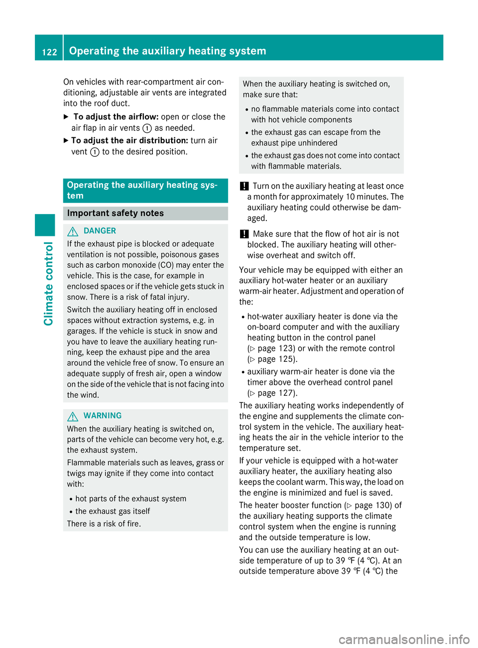
On vehicles with rear-compartment air con-
ditioning, adjustable air vents are integrated
into the roof duct.
X To adjust the airflow: open or close the
air flap in air vents 0043as needed.
X To adjust the air distribution: turn air
vent 0043to the desired position. Operating the auxiliary heating sys-
tem Important safety notes
G
DANGER
If the exhaust pipe is blocked or adequate
ventilation is not possible, poisonous gases
such as carbon monoxide (CO) may enter the vehicle. This is the case, for example in
enclosed spaces or if the vehicle gets stuck in
snow. There is a risk of fatal injury.
Switch the auxiliary heating off in enclosed
spaces without extraction systems, e.g. in
garages. If the vehicle is stuck in snow and
you have to leave the auxiliary heating run-
ning, keep the exhaust pipe and the area
around the vehicle free of snow. To ensure an adequate supply of fresh air, open a window
on the side of the vehicle that is not facing into
the wind. G
WARNING
When the auxiliary heating is switched on,
parts of the vehicle can become very hot, e.g. the exhaust system.
Flammable materials such as leaves, grass or
twigs may ignite if they come into contact
with:
R hot parts of the exhaust system
R the exhaust gas itself
There is a risk of fire. When the auxiliary heating is switched on,
make sure that:
R no flammable materials come into contact
with hot vehicle components
R the exhaust gas can escape from the
exhaust pipe unhindered
R the exhaust gas does not come into contact
with flammable materials.
! Turn on the auxiliary heating at least once
a month for approximately 10 minutes. The
auxiliary heating could otherwise be dam-
aged.
! Make sure that the flow of hot air is not
blocked. The auxiliary heating will other-
wise overheat and switch off.
Your vehicle may be equipped with either an
auxiliary hot-water heater or an auxiliary
warm-air heater. Adjustment and operation of the:
R hot-water auxiliary heater is done via the
on-board computer and with the auxiliary
heating button in the control panel
(Y page 123) or with the remote control
(Y page 125).
R auxiliary warm-air heater is done via the
timer above the overhead control panel
(Y page 127).
The auxiliary heating works independently of
the engine and supplements the climate con- trol system in the vehicle. The auxiliary heat-
ing heats the air in the vehicle interior to the
temperature set.
If your vehicle is equipped with a hot-water
auxiliary heater, the auxiliary heating also
keeps the coolant warm. This way, the load on
the engine is minimized and fuel is saved.
The heater booster function (Y page 130) of
the auxiliary heating supports the climate
control system when the engine is running
and the outside temperature is low.
You can use the auxiliary heating at an out-
side temperature of up to 39 ‡ (4 †). At an
outside temperature above 39 ‡ (4 †) the 122
Operating the auxiliary heating systemClimate control
Page 127 of 334
Setting the switch-on time
X Use the same method to select a switch-on
time as described in the "Preselecting a
switch-on time" section.
On-board computer without steering
wheel buttons
X Press the 0045reset button on the instru-
ment cluster.
The hour display flashes.
X Use the 0074and 0075buttons on the instru-
ment cluster to set the hours.
X Press the 0045reset button
The minute display flashes.
X Use the 0074and 0075buttons to set the
minutes.
The switch-on time is set and selected.
On-board computer with steering wheel
buttons
X Press the 0063button on the steering
wheel.
The display shows the Hours
Hours menu.
X Use the 0081and0082 buttons on the
steering wheel to set the hours.
X Press the 0063button.
The display shows the Minutes
Minutes menu.
X Use the 0081and0082 buttons to set the
minutes.
X Press the 0080button.
The switch-on time is set and selected. Operation with the remote control
Important information You can switch the auxiliary heating on/off
and set the operating duration using the
remote control. You can use up to 4 remote
control units on the vehicle. These must be
synchronized for the receiver in your vehicle
(Y page 126). The remote control has a maximum range of
approximately 600 meters. This range is
reduced by:
R sources of interference
R solid objects between the remote control
and the vehicle
R the remote control being in an unfavorable
position in relation to the vehicle
R transmitting from an enclosed space
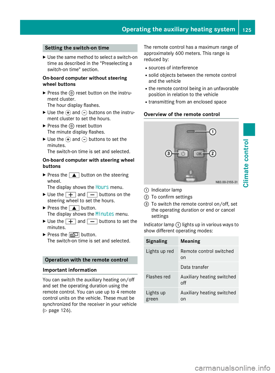
Overview of the remote control 0043
Indicator lamp
0044 To confirm settings
0087 To switch the remote control on/off, set
the operating duration or end or cancel
settings
Indicator lamp 0043lights up in various ways to
show different operating modes: Signaling Meaning
Lights up red Remote control switched
on
Data transfer
Flashes red Auxiliary heating switched
off
Lights up
green Auxiliary heating switched
onOperating the auxiliary heating system
125Climate control Z