reset MERCEDES-BENZ SPRINTER 2016 MY16 Operator’s Manual
[x] Cancel search | Manufacturer: MERCEDES-BENZ, Model Year: 2016, Model line: SPRINTER, Model: MERCEDES-BENZ SPRINTER 2016Pages: 290, PDF Size: 6.44 MB
Page 18 of 290
Correct usage .................................. 41
Display message ............................ 184
Fastening ........................................ .42
Important safety guidelines .............4 0
Introduction .....................................4 0
Releasin g ......................................... 42
Warning lamp ................................. 203
Warning lamp (function) ................... 43
Seat heating ......................................... 76
Seats
Adjusting lumbar support ................ 73
Adjusting the front-passenger
seat .................................................. 73
Adjusting the head restraint ............ 76
Armrest ............................................ 76
Cleaning the cover ......................... 238
Correct driver's seat position ........... 72
Folding seat ..................................... 74
Important safety notes .................... 72
Rear bench seat ............................... 75
Seat heating .................................... 76
Setting the driver's seat ................... 73
Swivel seat ....................................... 73
Twin front-passenger seat ................ 74
Securing loads
Important safety notes .................. 214
Selector lever
Cleaning ......................................... 238
Sensors (cleaning instructions) ....... 236
Service center
see Qualified specialist workshop
Service interval display
Calling up the service due date ...... 226
Exceeding a service due date ........ 226
Notes ............................................. 226
Service due date (automatic dis-
play) ............................................... 226
Service products
Brake fluid ..................................... 283
Coolant (engine) ............................ 283
Diesel Exhaust Fluid (DEF) ............. 279
Engine oil ....................................... 280
Fuel ................................................ 277
Important safety notes .................. 277
Power steering fluid ....................... 283
Refrigerant ..................................... 284
Transmission oi l ............................. 282
W
asher fluid ................................... 284 Setting the air distribution
............... 102
Setting the airflow ............................ 102
Setting the clock
Vehicles with steering wheel but-
tons ............................................... 171
Vehicles without steering wheel
buttons .......................................... 164
Settings
Resetting all (vehicles with steer-
ing wheel buttons) ......................... 168
Resetting submenus (vehicles
with steering wheel buttons) ......... 168
Short journeys (diesel particle fil-
ter) ...................................................... 134
Side impact air bag ............................. 45
Side windows
Cleaning ......................................... 235
Hinged side windows ....................... 70
Important safety information ........... 70
Opening/closing .............................. 71
Overview .......................................... 70
Problem (malfunction) ..................... 71
Resetting ......................................... 71
Sliding door
Cleaning ......................................... 237
Closing assist ................................... 66
Important safety notes .................... 65
Opening/closing .............................. 65
Opening/closing from the inside ..... 66
Opening/closing from the out-
side .................................................. 66
SmartKey
Changing the battery ....................... 61
Changing the locking system set-
tings ............................................... 173
Checking the battery ....................... 61
Display message ............................ 193
Door central locking/unlocking ....... 59
Important safety notes .................... 59
Loss ................................................. 63
Problem (malfunction) ..................... 63
SmartKey positions (ignition lock) .. 119
Snow chains ...................................... 249
Sockets .............................................. 210
Spare wheel
General notes ................................ 273
Important safety notes .................. 272
16Index
Page 21 of 290
Sidewall (definition) ....................... 265
Snow chains .................................. 249
Speed rating (definition) ................ 264
Storing ........................................... 267
Structure and characteristics
(definition) ..................................... 264
Summer tires ................................. 249
TIN (Tire Identification Number)
(definition) ..................................... 265
Tire bead (definition) ...................... 265
Tire pressure (definition) ................ 265
Tire pressures (recommended) ...... 264
Tire size (data) ....................... 257, 272
Tire size designation, load-bearing
capacity, speed rating .................... 261
Tire tread ....................................... 248
Tire tread (definition) ..................... 265
Total load limit (definition) ............. 266
Traction (definition) ....................... 266
TWR (permissible trailer drawbar
noseweight) (definition) ................. 266
Uniform Tire Quality Grading
Standards (definition) .................... 264
Wear indicator (definition) ............. 266
Wheel rim (definition) .................... 264
Top Tether ............................................ 50
Touchshift (automatic transmis-
sion) .................................................... 125
Tow-away alarm
Arming/deactivating ........................ 57
Deactivating ..................................... 57
Operation ......................................... 57
Tow-starting
Emergency engine starting ............ 246
Important safety notes .................. 243
Towing
If the vehicle is stuck ..................... 245
Installing/removing the towing
eye ................................................. 244
With a raised front or rear axle ...... 245
Towing a trailer
Axle load, permissible .................... 287
Cleaning the trailer tow hitch ......... 237
Coupling up a trailer ...................... 157
Decoupling a trailer ....................... 159
Driving tips .................................... 155
Important safety notes .................. 155
Notes on retrofitting ...................... 286 Trailer loads ................................... 287
Tow ing aw
ay
Important safety guidelines ........... 243
In the event of malfunctions .......... 244
With both axles on the ground ....... 245
Trailer
Brake force booster malfunction ... 195
Trailer coupling
see Towing a trailer
Trailer loads and drawbar nose-
weights ............................................... 159
Trailer towing
Blind Spot Assist ............................ 146
PARKTRONIC ................................. 153
Permissible trailer loads and
drawbar noseweights ..................... 159
Transmission
see Automatic transmission
Transmission oil ................................ 282
Transport
Loading guidelines ......................... 212
Vehicle ........................................... 246
Transport by rail ................................ 135
Transportation
Rail ................................................ 135
Transporting
Load distribution ............................ 214
Securing a load .............................. 214
Trim pieces (cleaning instruc-
tions) .................................................. 238
Trip computer (on-board com-
puter) .................................................. 174
Trip meter
see Trip odometer
Trip odometer
Display (vehicles with steering
wheel buttons) ............................... 167
Display (vehicles without steering
wheel buttons) ............................... 163
Resetting ....................................... 162
see Trip computer (on-board computer)
Turn signals
Replacing bulbs (front) ..................... 88
Replacing bulbs (rear) ...................... 89
Switching on/off .............................. 81
Turn signals (Chassis Cab)
Replacing bulbs (rear) ...................... 90
Index19
Page 34 of 290
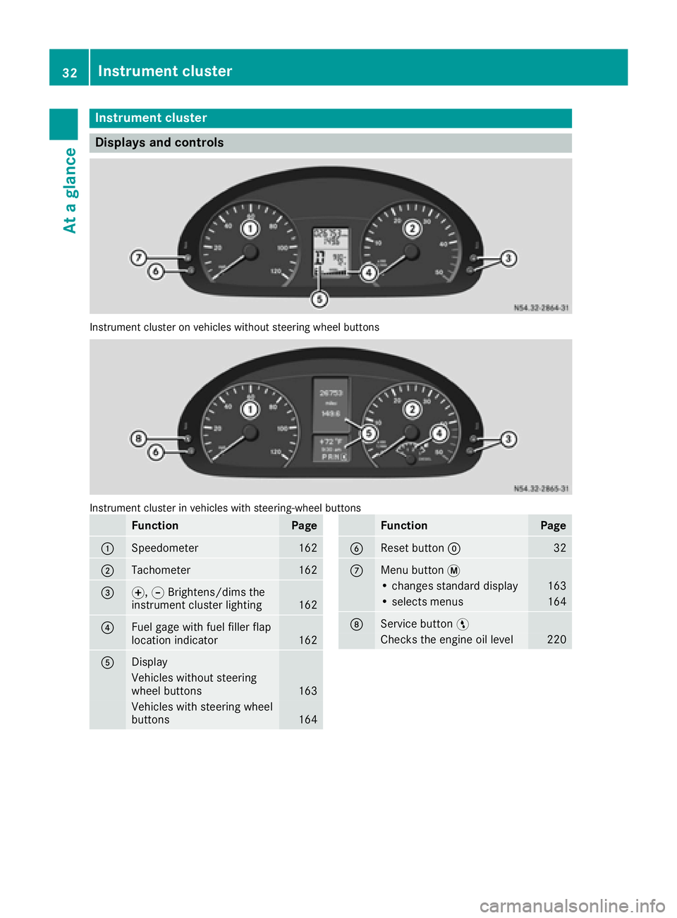
Instrument cluster
Displays and controls
Instrumentcluste ron vehicles without steering whee lbuttons
Instrumen tcluste rin vehicles wit hsteering-wheel buttons
FunctionPag e
:Speedometer162
;Tachometer162
=f, gBrightens/dims th e
instrumen tcluste rlighting16 2
?Fue lgage wit hfuel filler flap
location indicator16 2
ADisplay
Vehicles without steering
whee lbuttons16 3
Vehicles wit hsteering whee l
buttons16 4
FunctionPag e
BReset butto n932
CMen ubutto n4
• changes standard display16 3
•select smenus16 4
DService butto nË
Checks th eengin eoil level22 0
32Instrument cluster
At a glance
Page 73 of 290
GWARNING
If children operate the side windows they
could become trapped, particularly if they are left unsupervised. There is a risk of injury.
Activate the override feature for the rear side
windows. When leaving the vehicle, always
take the SmartKey with you and lock the vehi-
cle. Never leave children unsupervised in the
vehicle.
GWARNING
If persons, particularly children are subjected to prolonged exposure to extreme heat or
cold, there is a risk of injury, possibly even
fatal. Never leave children unattended in the
vehicle.
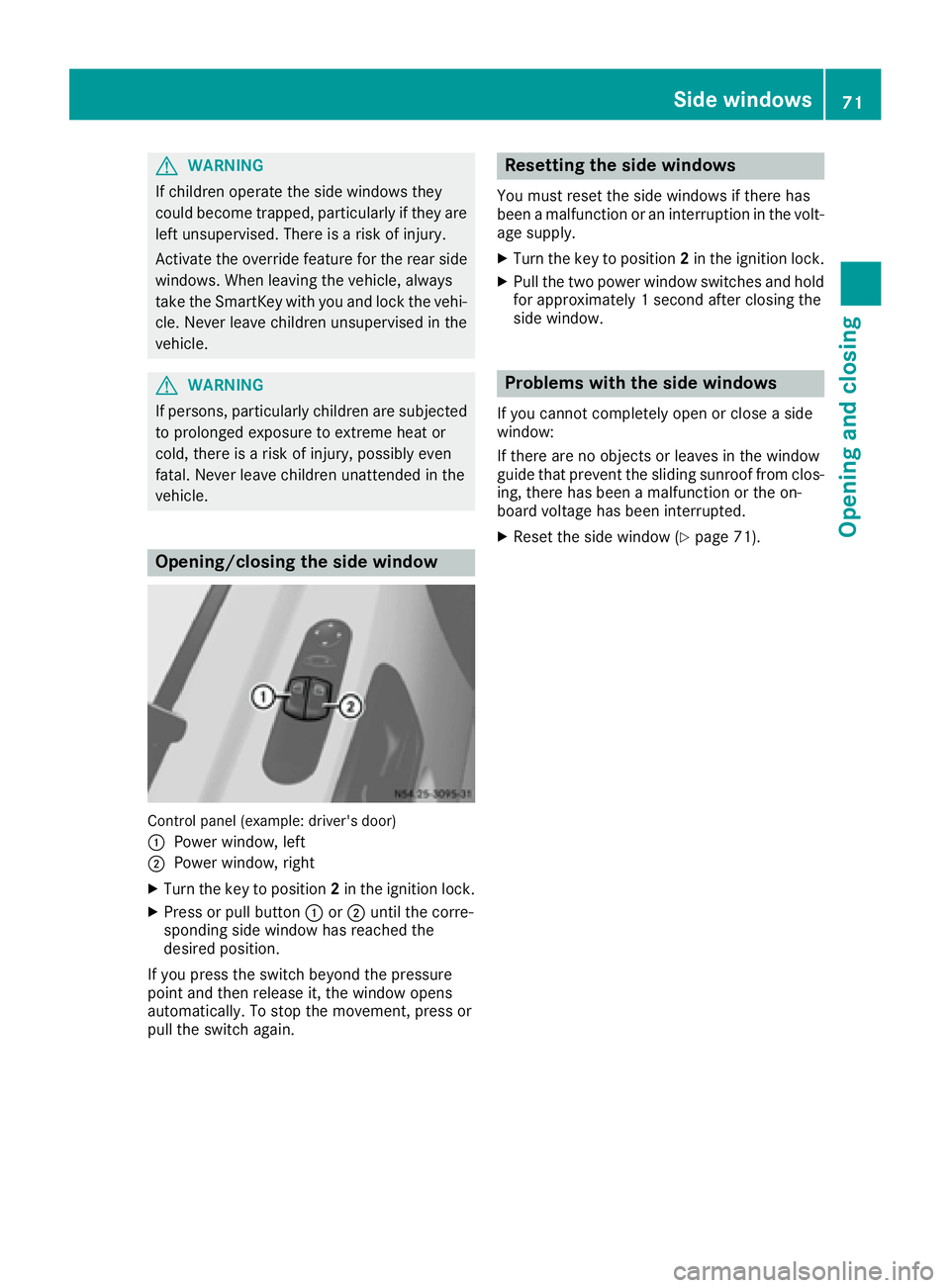
Opening/closing the side window
Control panel (example: driver's door)
:
Power window, left
;Power window, right
XTurn the key to position 2in the ignition lock.
XPress or pull button :or; until the corre-
sponding side window has reached the
desired position.
If you press the switch beyond the pressure
point and then release it, the window opens
automatically. To stop the movement, press or
pull the switch again.
Resetting the side windows
You must reset the side windows if there has
been a malfunction or an interruption in the volt-
age supply.
XTurn the key to position 2in the ignition lock.
XPull the two power window switches and hold
for approximately 1 second after closing the
side window.
Problems with the side windows
If you cannot completely open or close a side
window:
If there are no objects or leaves in the window
guide that prevent the sliding sunroof from clos-
ing, there has been a malfunction or the on-
board voltage has been interrupted.
XReset the side window (Ypage 71).
Side windows71
Opening and closing
Z
Page 111 of 290
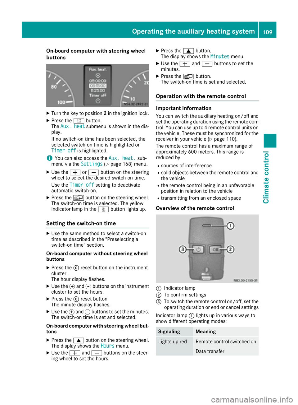
On-board computer with steering wheel
buttons
XTurn the key to position2in the ignition lock.
XPress the ybutton.
The Aux. heatsubmenu is shown in the dis-
play.
If no switch-on time has been selected, the
selected switch-on time is highlighted or
Timer off
is highlighted.
iYou can also access the Aux. heat.sub-
menu via the Settings(Ypage 168) menu.
XUse theWorX button on the steering
wheel to select the desired switch-on time.
Use the Timer off
setting to deactivate
automatic switch-on.
XPress the Vbutton on the steering wheel.
The switch-on time is selected. The yellow
indicator lamp in the ybutton lights up.
Setting the switch-on time
XUse the same method to select a switch-on
time as described in the "Preselecting a
switch-on time" section.
On-board computer without steering wheel
buttons
XPress the 9reset button on the instrument
cluster.
The hour display flashes.
XUse the fand gbuttons on the instrument
cluster to set the hours.
XPress the 9reset button
The minute display flashes.
XUse the fand gbuttons to set the minutes.
The switch-on time is set and selected.
On-board computer with steering wheel but-
tons
XPress the 9button on the steering wheel.
The display shows the Hoursmenu.
XUse theWandX buttons on the steer-
ing wheel to set the hours.
XPress the 9button.
The display shows the Minutesmenu.
XUse theWandX buttons to set the
minutes.
XPress the Vbutton.
The switch-on time is set and selected.
Operation with the remote control
Important information
You can switch the auxiliary heating on/off and
set the operating duration using the remote con-
trol. You can use up to 4 remote control units on
the vehicle. These must be synchronized for the
receiver in your vehicle (
Ypage 110).
The remote control has a maximum range of
approximately 600 meters. This range is
reduced by:
Rsources of interference
Rsolid objects between the remote control and
the vehicle
Rthe remote control being in an unfavorable
position in relation to the vehicle
Rtransmitting from an enclosed space
Overview of the remote control
:Indicator lamp
;To confirm settings
=To switch the remote control on/off, set the operating duration or end or cancel settings
Indicator lamp :lights up in various ways to
show different operating modes:
SignalingMeaning
Lights up redRemote control switched on
Data transfer
Operating the auxiliary heating system109
Climate control
Z
Page 117 of 290
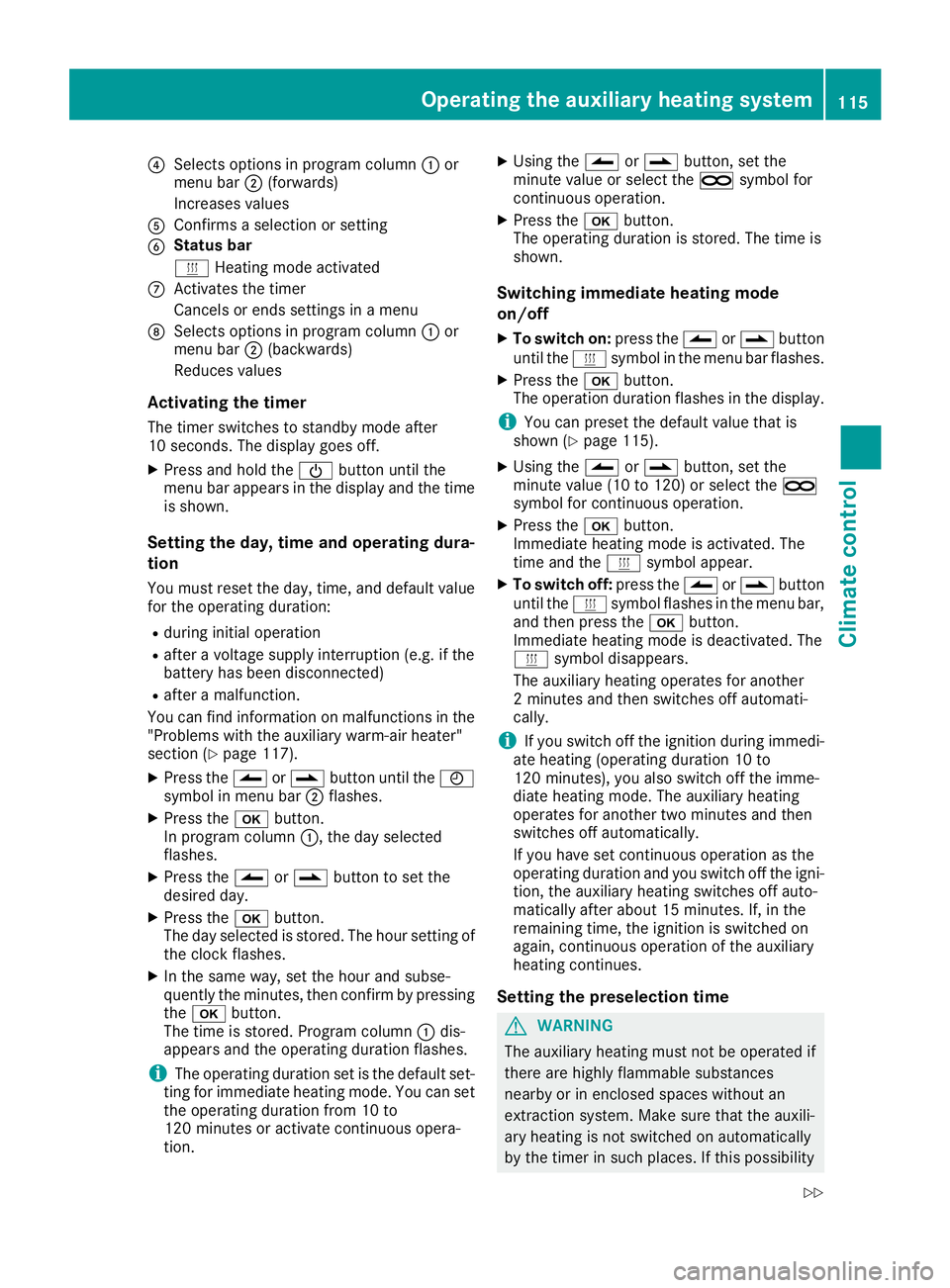
?Selects options in program column:or
menu bar ;(forwards)
Increases values
AConfirms a selection or setting
BStatus bar
y Heating mode activated
CActivates the timer
Cancels or ends settings in a menu
DSelects options in program column :or
menu bar ;(backwards)
Reduces values
Activating the timer
The timer switches to standby mode after
10 seconds. The display goes off.
XPress and hold the Übutton until the
menu bar appears in the display and the time
is shown.
Setting the day, time and operating dura-
tion
You must reset the day, time, and default value
for the operating duration:
Rduring initial operation
Rafter a voltage supply interruption (e.g. if the
battery has been disconnected)
Rafter a malfunction.
You can find information on malfunctions in the
"Problems with the auxiliary warm-air heater"
section (
Ypage 117).
XPress the Ûorâ button until the Ñ
symbol in menu bar ;flashes.
XPress the bbutton.
In program column :, the day selected
flashes.
XPress the Ûorâ button to set the
desired day.
XPress the bbutton.
The day selected is stored. The hour setting of the clock flashes.
XIn the same way, set the hour and subse-
quently the minutes, then confirm by pressingthe b button.
The time is stored. Program column :dis-
appea rs a
nd the operating duration flashes.
iThe operating duration set is the default set-
ting for immediate heating mode. You can set
the operating duration from 10 to
120 minutes or activate continuous opera-
tion.
XUsing the Ûorâ button, set the
minute value or select the àsymbol for
continuous operation.
XPress the bbutton.
The operating duration is stored. The time is
shown.
Switching immediate heating mode
on/off
XTo switch on: press theÛorâ button
until the ysymbol in the menu bar flashes.
XPress the bbutton.
The operation duration flashes in the display.
iYou can preset the default value that is
shown (Ypage 115).
XUsing the Ûorâ button, set the
minute value (10 to 120) or select the à
symbol for continuous operation.
XPress the bbutton.
Immediate heating mode is activated. The
time and the ysymbol appear.
XTo switch off: press theÛorâ button
until the ysymbol flashes in the menu bar,
and then press the bbutton.
Immediate heating mode is deactivated. The
y symbol disappears.
The auxiliary heating operates for another
2 minutes and then switches off automati-
cally.
iIf you switch off the ignition during immedi-
ate heating (operating duration 10 to
120 minutes), you also switch off the imme-
diate heating mode. The auxiliary heati
ng
operates for another two minutes and then
switches off automatically.
If you have set continuous operation as the
operating duration and you switch off the igni-
tion, the auxiliary heating switches off auto-
matically after about 15 minutes. If, in the
remaining time, the ignition is switched on
again, continuous operation of the auxiliary
heating continues.
Setting the preselection time
GWARNING
The auxiliary heating must not be operated if
there are highly flammable substances
nearby or in enclosed spaces without an
extraction system. Make sure that the auxili-
ary heating is not switched on automatically
by the timer in such places. If this possibility
Operating the auxiliary heating system115
Climate control
Z
Page 121 of 290
tery isolating switch. You could otherwise
damage electrical system components.
You can use the battery isolating switch to dis-
connect the power supply to all your vehicle's
consumers. This will prevent uncontrolled bat-
tery discharge caused by off-load current con-
sumption.
If your vehicle is equipped with an auxiliary bat-
tery in the engine compartment, you will need to
disconnect both batteries. Only then is the elec-
trical system fully disconnected from the power
supply.
iOnly switch the vehicle to de-energized
using the battery main switch if:
Rthe vehicle is stationary for a lengthy period
Rit is absolutely necessary
After the power supply has been activated,
you will need to reset the side windows
(
Ypage 71).
Switching off the power supply
!When you clamp the connector under the
accelerator pedal, make sure that the con-
nector does not become damaged or dirty. It
may otherwise not be possible to restore the
electrical connection when the parts are reas-
sembled.
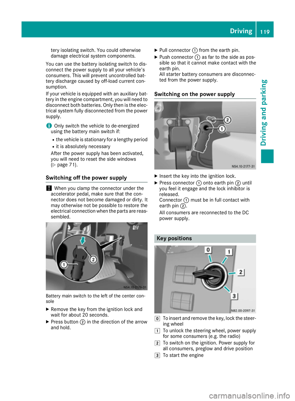
Battery main switch to the left of the center con-
sole
XRemove the key from the ignition lock and
wait for about 20 second s.
XPressbu tton ;in the direction of the arrow
and hold.
XPull connector :from the earth pin.
XPush connector :as far to the side as pos-
sible so that it cannot make contact with the
earth pin.
All starter battery consumers are disconnec-
ted from the power supply.
Switching on the power supply
XInsert the key into the ignition lock.
XPress connector :onto earth pin ;until
you feel it engage and the lock inhibitor is
released.
Connector :must be in full contact with
earth pin ;.
All consumers are reconnected to the DC
power supply.
Key positions
gTo insert and remove the key, lock the steer-
ing wheel
1To unlock the steering wheel, power supply
for some consumers (e.g. the radio)
2To switch on the ignition. Power supply for
all consumers, preglow and drive position
3To start the engine
Driving119
Dr iving an d parking
Z
Page 137 of 290
Low-beam headlamps
If you are traveling in countries where vehicles
are driven on the opposite side of the road to
that in which the vehicle is registered, you will
need to:
Rhave the halogen headlamps partially masked
Rhave the Bi-Xenon headlamps set to symmet-
rical low beam
This prevents glare to oncoming traffic and no
longer illuminates the edge of the road to the
same height and distance.
Have the headlamps masked or adjusted at a
qualified specialist workshop before you cross
the border, but as close to it as possible.
When you return from your journey, and as close
to the border as possible, you will need to:
Rremove the adhesive surfaces from your hal-
ogen headlamps and clean the glass of the
headlamps if necessary
Rhave the Bi-Xenon headlamps reset to asym-
metrical low beam at a qualified specialist
workshop
Transport by rail
Transporting your vehicle by rail may be subject
to certain restrictions or require special meas-
ures to be taken in some countries due to vary- ing tunnel heights and loading standards.
You can obtain further information from any
authorized Sprinter dealer.
Brakes
Important safety notes
GWARNING
If you shift down on a slippery road surface in an attempt to increase the engine's braking
effect, the drive wheels could lose their grip.
There is an increased danger of skidding and
accidents.
Do not shift down for additional engine brak-
ing on a slippery road surface.
GWARNING
If you rest your foot on the brake pedal while
driving, the braking system can overheat. This
increases the stopping distance and can even
cause the braking system to fail. There is a
risk of an accident.
Never use the brake pedal as a footrest. Never
depress the brake pedal and the accelerator
pedal at the same time.
!Depressing the brake pedal constantly
results in excessive and premature wear to
the brake pads.
Downhill gradients
!Depressing the brake pedal constantly
results in excessive and premature wear to
the brake pads.
On long and steep downhill gradients, you
should change down to shift range 2or1 in
good time. This should be observed in particular
when driving with a laden vehicle and when tow-
ing a trailer.
iYou must also change the shift range in
good time when cruise control is switched on.
You thereby make use of the braking effect of
the engine and do not have to brake as often to
maintain the speed. This relieves the load on the
service brake and prevents the brakes from
overheating and wearing too quickly.
Heavy and light loads
GWARNING
If you rest your foot on the brake pedal while
driving, the braking system can overheat. This increases the stopping distance and can even
cause the braking system to fail. There is a
risk of an accident.
Never use the brake pedal as a footrest. Never
depress the brake pedal and the accelerator
pedal at the same time.
!Depressing the brake pedal constantly
results in excessive and premature wear to
the brake pads.
If the brakes have been subjected to a heavy
load, do not stop the vehicle immediately. Drive
on for a short while. The brakes are cooled down
more quickly in the airflow.
Driving tips135
Driving and parking
Z
Page 151 of 290
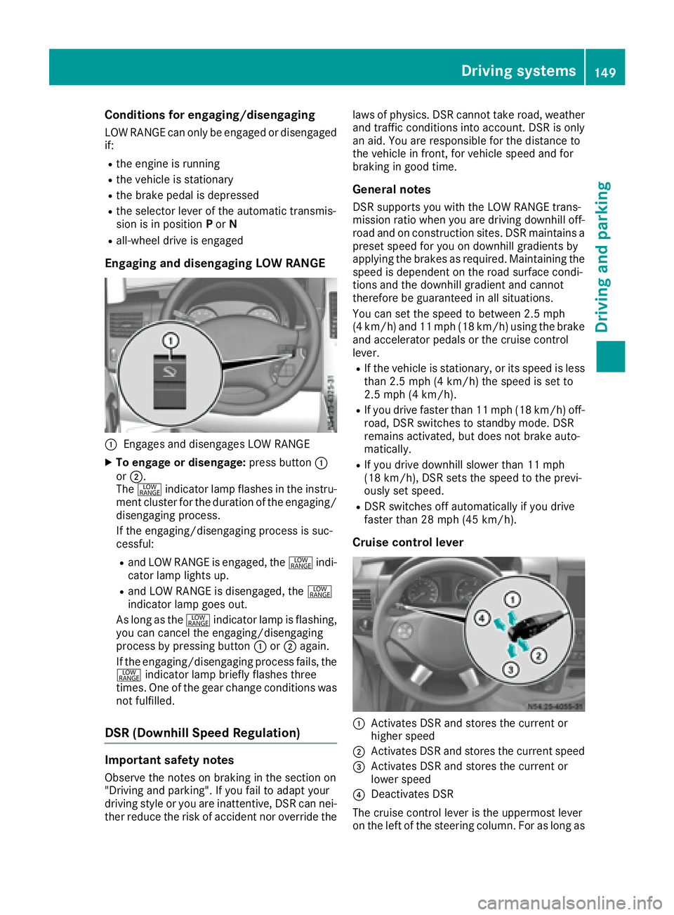
Conditions for engaging/disengaging
LOW RANGE can only be engaged or disengaged
if:
Rthe engine is running
Rthe vehicle is stationary
Rthe brake pedal is depressed
Rthe selector lever of the automatic transmis-
sion is in positionPor N
Rall-wheel drive is engaged
Engaging and disengaging LOW RANGE
:Engages and disengages LOW RANGE
XTo engage or disengage: press button:
or ;.
The + indicator lamp flashes in the instru-
ment cluster for the duration of the engaging/
disengaging process.
If the engaging/disengaging process is suc-
cessful:
Rand LOW RANGE is engaged, the +indi-
cator lamp lights up.
Rand LOW RANGE is disengaged, the +
indicator lamp goes out.
As long as the +indicator lamp is flashing,
you can cancel the engaging/disengaging
process by pressing button :or; again.
If the engaging/disengaging process fails, the + indicator lamp briefly flashes three
times. One of the gear change conditions was
not fulfilled.
DSR (Downhill Speed Regulation)
Important safety notes
Observe the notes on braking in the section on
"Driving and parking". If you fail to adapt your
driving style or you are inattentive, DSR can nei-
ther reduce the risk of accident nor override the laws of physics. DSR cannot take road, weather
and traffic conditions into account. DSR is only
an aid. You are responsible for the distance to
the vehicle in front, for vehicle speed and for
braking in good time.
General notes
DSR supports you with the LOW RANGE trans-
mission ratio when you are driving downhill off-
road and on construction sites. DSR maintains a
preset speed for you on downhill gradients by
applying the brakes as required. Maintaining the
speed is dependent on the road surface condi-
tions and the downhill gradient and cannot
therefore be guaranteed in all situations.
You can set the speed to between 2.5 mph
(4 km/h) and 11 mph (18 km/h) using the brake
and accelerator pedals or the cruise control
lever.
RIf the vehicle is stationary, or its speed is less
than 2.5 mph (4 km/h) the speed is set to
2.5 mph (4 km/h).
RIf you drive faster than 11 mph (18 km/h) off-
road, DSR switches to standby mode. DSR
remains activated, but does not brake auto-
matically.
RIf you drive downhill slower than 11 mph
(18 km/h), DSR sets the speed to the previ-
ously set speed.
RDSR switches off automatically if you drive
faster than 28 mph (45 km/h).
Cruise control lever
:Activates DSR and stores the current or
higher speed
;Activates DSR and stores the current speed
=Activates DSR and stores the current or
lower speed
?Deactivates DSR
The cruise control lever is the uppermost lever
on the left of the steering column. For as long as
Driving systems149
Driving and parking
Z
Page 156 of 290
Problems with PARKTRONIC
ProblemPossible causes/consequences andMSolutions
Only the red segments in
the PARKTRONIC warn-
ing displays are lit.
A warning tone also
sounds for approx-
imately 2 seconds.
PARKTRONIC is deacti-
vated after approx-
imately 20 seconds.
The indicator lamp of the
f button lights up
and the red segments in
the PARKTRONIC warn-
ing display go out.PARKTRONIC has malfunctioned and has switched itself off.
XIf problems persist, have PARKTRONIC checked at a qualified spe- cialist workshop.
The PARKTRONIC warn-
ing displays implausible
distances.
For example, all the seg-
ments may be lit even
though there is no obsta-
cle present.The PARKTRONIC sensors are dirty or iced up.
XClean the PARKTRONIC sensors (Ypage 236).
XTurn the key to position 2again in the ignition lock.
The license plate or other parts attached near the sensors may not be
secured correctly.
XCheck the license plate and attachment parts near the sensors for
correct seating.
An external radio or ultrasonic source may be causing interference.
XCheck PARKTRONIC functions in a different location.
Rear view camera
Important safety notes
The rear view camera is only an aid. It cannot
replace your own awareness of the immediate
surroundings. You are responsible for safe
maneuvering, parking and pulling away. When
maneuvering, parking and pulling away, make
sure that there are no persons, animals or
objects in the maneuvering area.
The rear view camera is a visual parking aid.
Information on operation can be found in the
separate Audio 15 supplement.
The camera is in the middle of the roof above the
high-mounted brake lamp (
Ypage 236).
You can find information on cleaning the camera
in the "Maintenance and care" section
(
Ypage 236).
Working mode
ADR (working speed governor)
General notes
When activated, ADR automatically increases
the engine speed to a preset speed or a speed
you have set.
iAfter a cold start, the idling speed of the
engine is increased automatically. If the pre-
set working speed is lower than the increased idling speed, the working speed is only
reached once the engine has completed the
warm-up phase.
It is only possible to activate ADR with the
vehicle stationary and the parking brake
applied.
The selector lever of the automatic transmis-
sion must be in position P.
154Working mode
Driving and parking