turn signal MERCEDES-BENZ SPRINTER 2019 MY19 with 7” screen
[x] Cancel search | Manufacturer: MERCEDES-BENZ, Model Year: 2019, Model line: SPRINTER, Model: MERCEDES-BENZ SPRINTER 2019Pages: 354, PDF Size: 6.15 MB
Page 31 of 354
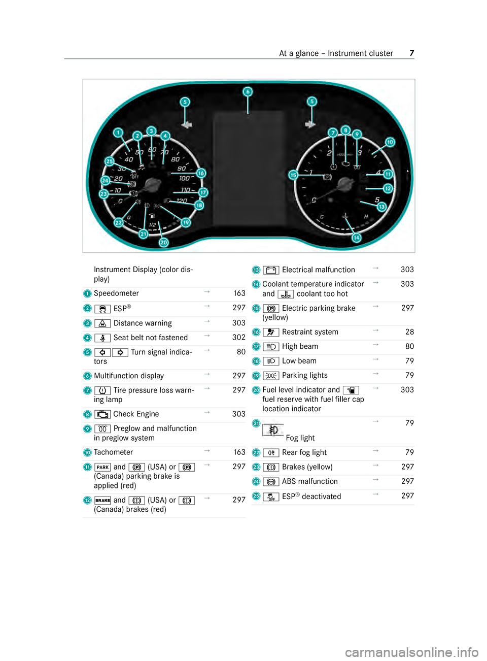
Instrument Display (color dis‐
play)
1 Speedome ter →
16 3
2 00E5 ESP®
→
297
3 00BA Distance warning →
303
4 00E9 Seat belt not fastened →
302
5 003E003D Turn signal indica‐
to rs →
80
6 Multifunction display →
297
7 0077 Tire pressure loss warn‐
ing lamp →
297
8 00B9 Check Engine →
303
9 0028 Preglow and malfunction
in preglow sy stem
A Tach ome ter →
16 3
B 0049 and0024 (USA) or 0024
(Canada) parking brake is
applied (red) →
297
C 0027 and004D (USA) or 004D
(Canada) brakes (red) →
297 D
003D Electrical malfunction →
303
E Coolant temp erature indicator
and 00AC coolant too hot →
303
F 0024 Electri c parking brake
(yellow) →
297
G 0075 Restra int sy stem →
28
H 0057 High beam →
80
I 0058 Low beam →
79
J 0060 Parking lights →
79
K Fuel le vel indicator and 00D4
fuel reser vewith fuel filler cap
location indicator →
303
L Fo
g light →
79
M 005E Rear fog light →
79
N 004D Brakes (yellow) →
297
O 0025 ABS malfunction →
297
P 00BB ESP®
deactivated →
297 At
aglance – In stru ment clus ter7
Page 32 of 354
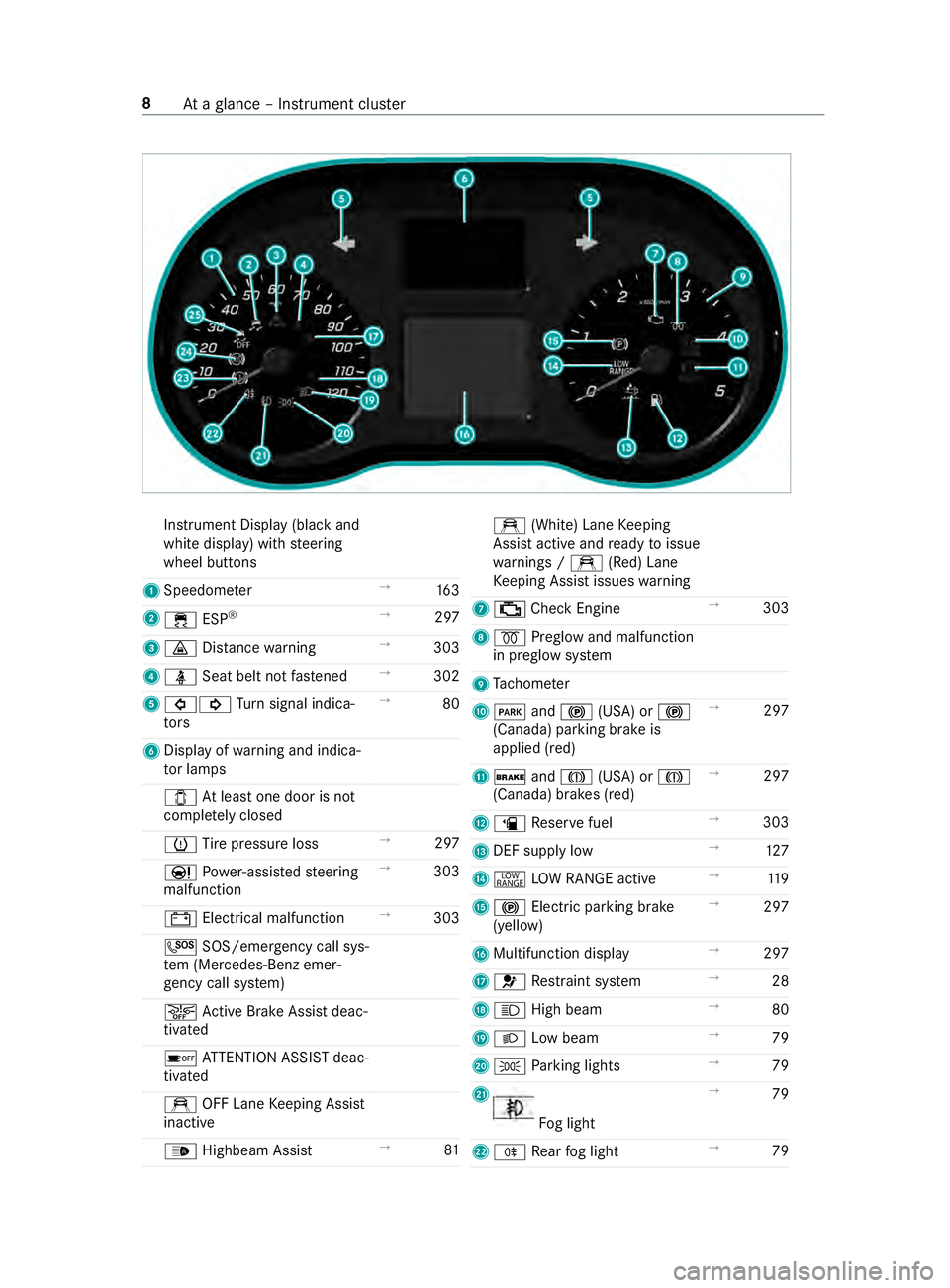
Instrument Display (black
and
white display) with steering
wheel buttons
1 Speedome ter →
16 3
2 00E5 ESP®
→
297
3 00BA Distance warning →
303
4 00E9 Seat belt not fastened →
302
5 003E003D Turn signal indica‐
to rs →
80
6 Displ ayofwa rning and indica‐
to r lamps
003E Atleast one door is not
comple tely closed
0077 Tire pressure loss →
297
00CC Powe r-assis tedsteering
malfunction →
303
003D Electrical malfunction →
303
0053 SOS/emergency call sys‐
te m (Mercedes-Benz emer‐
ge ncy call sy stem)
00D4 Active Brake Assi stdeac‐
tivated
00D7 ATTENTION ASSIST deac‐
tivated
e OFF Lane Keeping Assist
inactive
00CE Highbeam Assist →
81 e
(White) Lane Keeping
Assist active and ready toissue
wa rnings / e(Red) Lane
Ke eping Assist issues warning
7 00B9 Check Engine →
303
8 0028 Preglow and malfunction
in preglow sy stem
9 Tach ome ter
A 0049 and0024 (USA) or 0024
(Canada) parking brake is
applied (red) →
297
B 0027 and004D (USA) or 004D
(Canada) brakes (red) →
297
C 00D4 Reser vefuel →
303
D DEF supply low →
127
E 002E LOW RANGE active →
11 9
F 0024 Electric pa rking brake
(yellow) →
297
G Multifunction display →
297
H 0075 Restra int sy stem →
28
I 0057 High beam →
80
J 0058 Low beam →
79
K 0060 Parking lights →
79
L Fo
g light →
79
M 005E Rear fog light →
79 8
Ataglance – In stru ment clus ter
Page 69 of 354
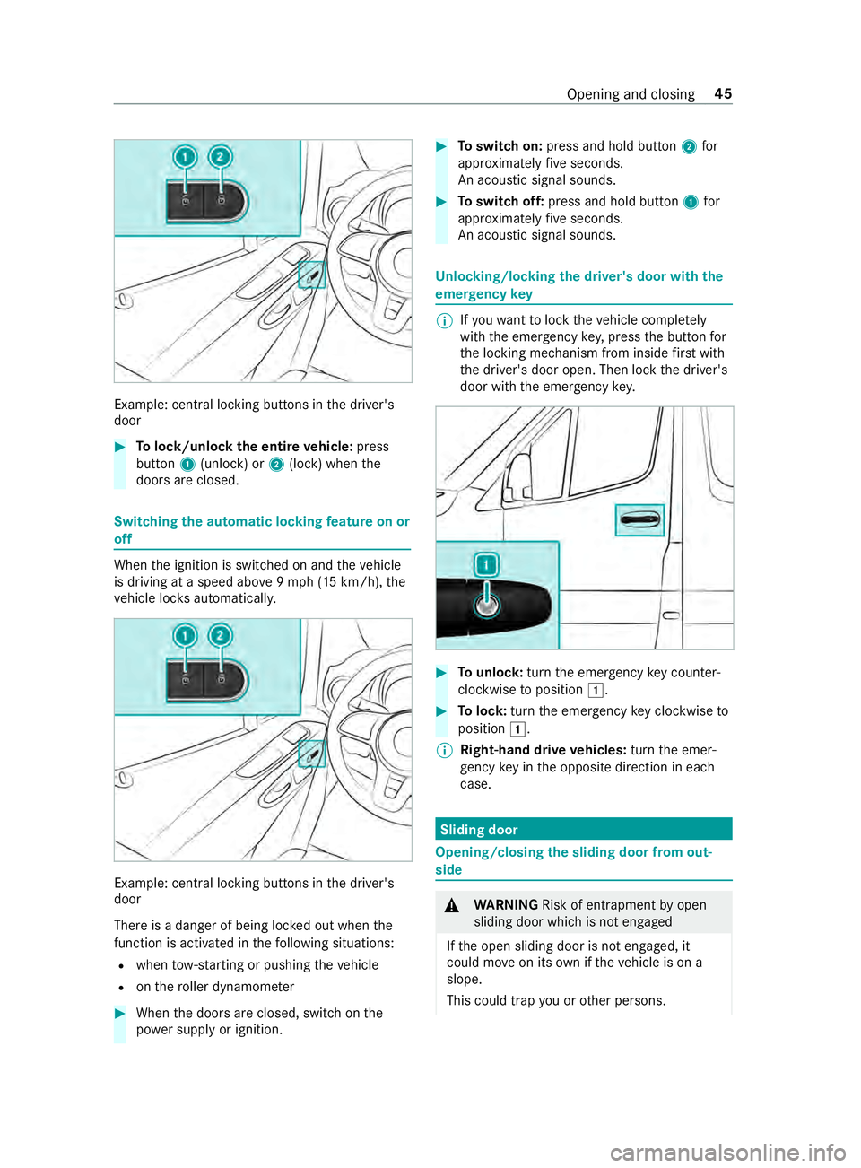
Example: central lo
cking buttons in the driver's
door #
Tolock/unlock the entire vehicle: press
button 1(unlock) or 2(lock) when the
doors are closed. Switching
the automatic locking feature on or
off When
the ignition is switched on and theve hicle
is driving at a speed abo ve9mp h (15 km/h), the
ve hicle loc ksautomaticall y. Example: central lo
cking buttons in the driver's
door
There is a danger of being loc ked out when the
function is activated in thefo llowing situations:
R when tow- starting or pushing theve hicle
R onthero ller dynamom eter #
When the doors are closed, switch on the
po we r supp lyor ignition. #
Toswitch on: press and hold button 2for
appr oximately five seconds.
An acoustic signal sounds. #
Toswitch off: press and hold button 1for
appr oximately five seconds.
An acoustic signal sounds. Un
locking/locking the driver's door with the
emer gency key %
If
yo uwa nttolock theve hicle comple tely
wi th th e emer gency key,press the button for
th e locking mechanism from inside firs t wi th
th e driver's door open. Then lock the driver's
door with the emer gency key. #
Tounlo ck:turn the emer gency key counter-
clo ckwise toposition 0047. #
Tolock: turnthe emer gency key clo ckwise to
position 0047.
% Right-hand drive
vehicles: turnthe emer‐
ge ncy key in the opposite direction in each
case. Sliding door
Opening/closing
the sliding door from out‐
side &
WARNING Risk of entrapment byopen
sliding door which is not engaged
If th e open sliding door is not engaged, it
could mo veon its own if theve hicle is on a
slope.
This could trap you or other persons. Opening and closing
45
Page 103 of 354
Exterior lighting
Note
s onchanging the lights when driving
abroad Ve
hicles with halogen or static LED head‐
lamps: Changing the headlamps is not neces‐
sar y.The legal requ irements will also be fulfilled
in countries with left and right-hand traf fic. In
fo rm ation about lighting sy stems and your
re sponsibility The
vehicle's various lighting sy stems are only
aids. The vehicle driver is responsible for adjust‐
ing theve hicle's lighting tothe pr evailing light,
visibilit y,statutory conditions and traf fic condi‐
tions. Light switch
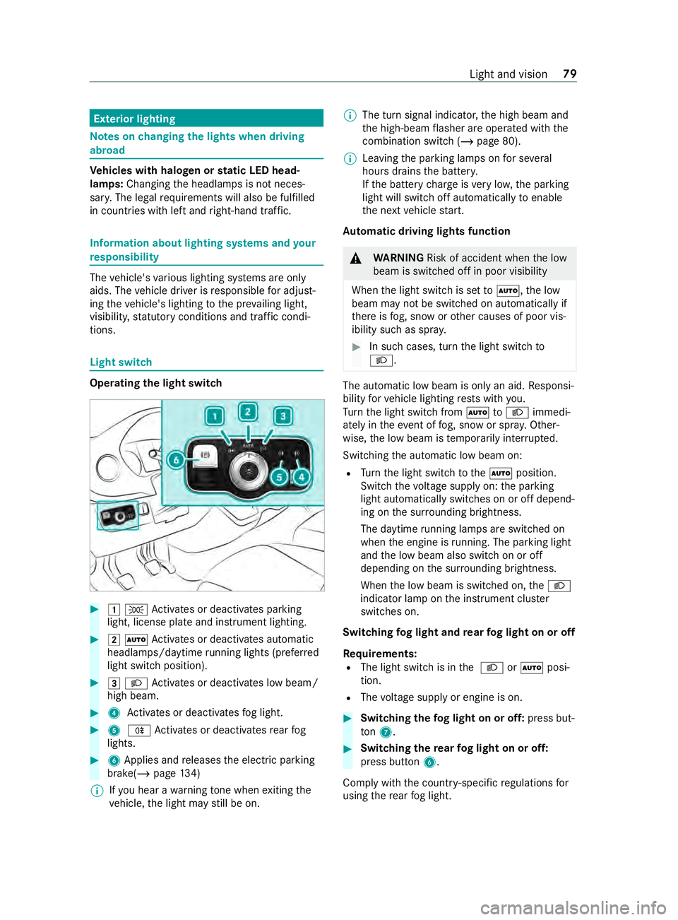
Operating the light switch
#
00470060 Activates or deacti vates parking
light, license plate and instrument lighting. #
00480058 Activates or deacti vates automatic
headlamp s/daytime running lights (p referred
light switch position). #
00490058 Activates or deacti vates low beam/
high beam. #
4 Activates or deacti vatesfo g light. #
5 005E Activates or deacti vatesre ar fog
lights. #
6Applies and releases the electric parking
brake(/ page134)
% If
yo u hear a warning tone when exiting the
ve hicle, the light may still be on. %
The turn signal indicator,
the high beam and
th e high-beam flasher are operated with the
combination switch (/ page 80).
% Leaving
the parking lamps on for se veral
hours drains the batter y.
If th e battery charge isvery low, the parking
light will switch off automatically toenable
th e next vehicle start.
Au tomatic driving lights function &
WARNING Risk of accident when the low
beam is switched off in poor visibility
When the light switch is set to0058 ,th e low
beam may not be switched on automatically if
th ere is fog, snow or other causes of poor vis‐
ibility such as spr ay. #
In such cases, turn the light switch to
0058 . The automatic low beam is only an aid.
Responsi‐
bility forve hicle lighting rests with you.
Tu rn the light switch from 0058to0058 immedi‐
ately in theev ent of fog, snow or spr ay. Other‐
wise, the low beam is temp orarily inter rupte d.
Switching the automatic low beam on:
R Turn the light switch tothe0058 position.
Switch thevo ltage supply on: the parking
light automatically switches on or off depend‐
ing on the sur rounding brightness.
The daytime running la mps are switched on
when the engine is running. The pa rking light
and the low beam also switch on or off
depending on the sur rounding brightness.
When the low beam is switched on, the0058
indicator lamp on the instrument clus ter
switches on.
Switching fog light and rear fog light on or off
Requ irements:
R The light switch is in the 0058 or0058 posi‐
tion.
R The voltage supply or engine is on. #
Switching thefo g light on or off: press but‐
to n7. #
Switching the rear fog light on or off:
press button 6.
Comply with the count ry-specific regulations for
using there ar fog light. Light and vision
79
Page 104 of 354
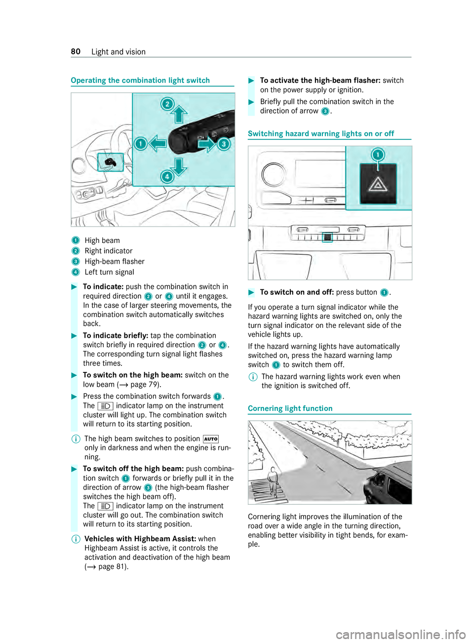
Operating
the combination light switch 1
High beam
2 Right indicator
3 High-beam flasher
4 Left turn signal #
Toindicate: pushthe combination switch in
re qu ired direction 2or4 until it engages.
In the case of larger steering mo vements, the
combination switch au tomatically switches
bac k. #
Toindicate briefl y:tapth e combination
switch briefly in required direction 2or4.
The cor responding turn signal light flashes
th re e times. #
Toswitch on the high beam: switchon the
low beam (/ page 79). #
Press the combination switch forw ards 1.
The 0057 indicator lamp on the instrument
clus ter will light up. The combination switch
will return toits starting position.
% The high beam swit ches toposition 0058
only in darkness and when the engine is run‐
ning. #
Toswitch off the high beam: push combina‐
tion swit ch1 forw ards or briefly pull it in the
direction of ar row3(the high-beam flasher
swit ches the high beam off).
The 0057 indicator lamp on the instrument
clus ter will go out. The combination switch
will return toits starting position.
% Ve
hicles with Highbeam Assis t:when
Highbeam Assist is active, it controls the
activation and deactivation of the high beam
(/ page 81). #
Toactivate the high-beam flasher: switch
on the po wer supp lyor ignition. #
Brief lypull the combination switch in the
direction of ar row3. Switching hazard
warning lights on or off #
Toswitch on and off: press button1.
If yo u operate a turn signal indicator while the
hazard warning lights are switched on, only the
turn signal indica tor on there leva nt side of the
ve hicle lights up.
If th e hazard warning lights ha veautomatically
swit ched on, press the hazard warning lamp
switch 1toswitch them off.
% The hazard
warning lights workeve n when
th e ignition is switched off. Cornering light function
Cornering light impr
ovesth e illumination of the
ro ad ove r a wide angle in the turning direction,
enabling better visibility in tight bends, forex am‐
ple. 80
Light and vision
Page 108 of 354
#
Allow the component parts tocool
down before replacing the bulbs. When
you are replacing the light bulb, obser ve
th efo llowing:
R Do not use any bulb that has been dropped or
has scratches on its glass tube. Otherwise,
th e bulb may explode.
R The bulb may explode if it is hot or if you
to uch, drop or sc ratch it.
R Stains on theglass tube reduce the bulb's
service life. Do not touch theglass tube with
yo ur bare hands. If necessar y,clean theglass
tube with alcohol or spirits in a cold state and
wipe it down with a lint-f ree clo th.
R Protect bulbs from humidity and do not bring
th em into contact with liquids.
Alw ays ensure the bulbs are firm lysecured.
If yo ur vehicle is equipped with LED lamps, you
can check this as follo ws :th e light cone will mo ve
from topto bottom and back again when the
engine starts. Forth is to wo rk,th e low beam
needs tohave been switched on before the
engine is star ted.
Bulbs and lights are a major part of vehicle
saf ety. Therefore, ensure that they are alw ays
wo rking. Ha vethe headlamp setting checkedre g‐
ular ly.
R Before changing the lamps, switch off the
ve hicle's lighting sy stem. This will pr event a
sho rtcircuit.
R Use bulbs only in closed lights that ha vebeen
designed forth em.
R Use only spare bulbs of the same type and
with the cor rect voltage.
If th e new bulb also does not light up, consult a
qu alified specialist workshop. Re
placing front light bulbs (vehicles with hal‐
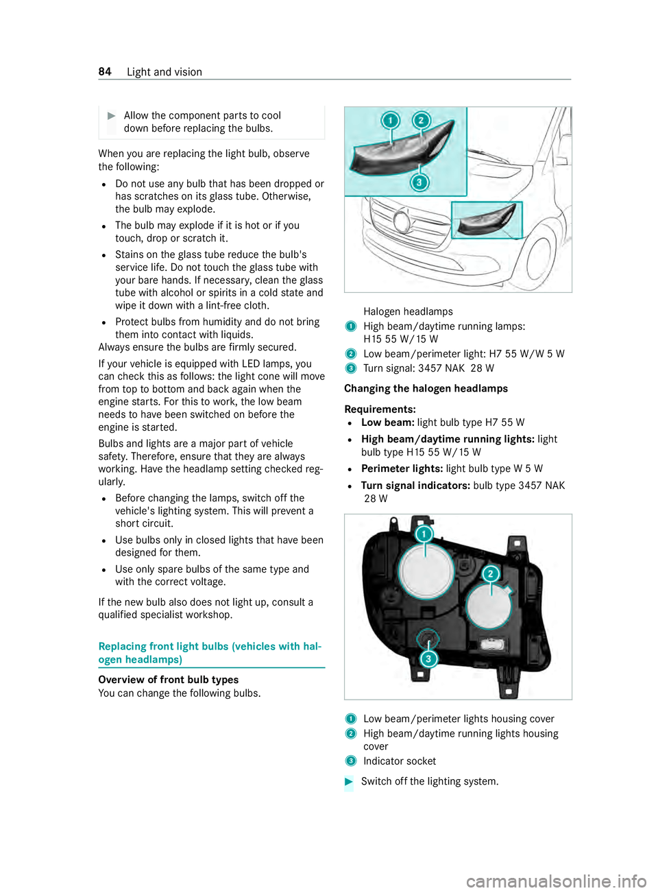
ogen headlamps) Overview of front bulb types
Yo
u can change thefo llowing bulbs. Halogen headlamps
1 High beam/daytime running la mps:
H15 55 W/15 W
2 Low beam/perime ter ligh t:H7 55 W/W 5 W
3 Turn signal: 3457 NAK 28 W
Changing the halogen headlamps
Re quirements:
R Low beam: light bulb type H7 55 W
R High beam/daytime running lights: light
bulb type H15 55 W/15 W
R Perime ter lights: light bulb type W 5 W
R Turn signal indicators: bulb type 3457NAK
28 W 1
Low beam/perime ter lights housing co ver
2 High beam/daytime running lights housing
co ver
3 Indicator soc ket #
Switch off the lighting sy stem. 84
Light and vision
Page 109 of 354
#
Low beam/perime ter lights: pull back
housing co ver1. #
Pull out the soc ketto wa rdsth ere ar. #
Remo vethe bulb from the soc ket. #
Inse rtthe new bulb into the soc ket su chthat
th e base of the bulb rests fully against the
base of the soc ket. #
Align and insert the soc ket. #
Attach housing co ver1. #
High beam/daytime running lights: pull
back housing co ver2. #
Turn the soc ket counter-clo ckwise and pull it
out. #
Remo vethe bulb from the soc ket. #
Inse rtthe new bulb into the soc ket su chthat
th e base of the bulb rests fully against the
base of the soc ket. #
Inse rtthe soc ket and turn it clo ckwise. #
Attach housing co ver2. #
Turn signal indicator: #
Turn soc ket3 counter-clo ckwise and
re mo veit. #
Gently turn the bulb counter-clockwise and
ta ke it out of the soc ket. #
Inse rtthe new bulb into the soc ket and turn it
clo ckwise. #
Insert soc ket3 and turn it clo ckwise.
Ad ditional turn signal light
Re quirements:
R Ad
ditional turn signal light (all-wheel
drive vehicles): bulb type P 21 W #
Switching off the lighting sy stem. #
Unscr ewscrews 1and remo velens 2. #
Gently turn the bulb counter-clockwise and
ta ke it out of the soc ket. #
Inse rtthe new bulb into the soc ket and turn it
clo ckwise. #
Place lens 2in position and tigh tenthe
scr ews 1. Re
placing rear light bulbs (Cargo Van and
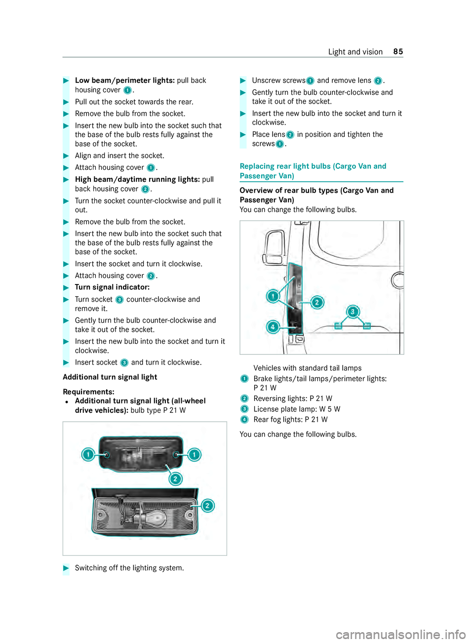
Pa ssenger Van) Overview of
rear bulb types (Cargo Van and
Pa ssenger Van)
Yo u can change thefo llowing bulbs. Ve
hicles with standard tail lamps
1 Brake lights/tail lamps/pe rime ter lights:
P 21 W
2 Reversing lights: P 21 W
3 License plate lamp: W 5 W
4 Rear fog lights: P 21 W
Yo u can change thefo llowing bulbs. Light and vision
85
Page 111 of 354
#
Switch off the lighting sy stem. #
Place a scr ewdriver, forex ample, at opening
2 between lamp 3and panel 1and care‐
fully pry off lamp 3. #
Remo velamp 3from panel 1. #
Rotate the bulb holder byaround 45° and
de tach it from the lamp. #
Remo vethe light bulb. #
Insert the new bulb into the bulb holder. #
Insert the bulb holder into the lamp and
ro tate itby around 45°. #
Insert the lamp into the panel opening until it
engages. Re
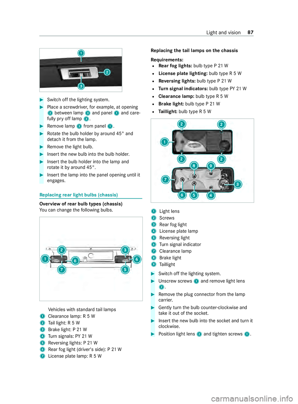
placing rear light bulbs (chassis) Overview of
rear bulb types (chassis)
Yo u can change thefo llowing bulbs. Ve
hicles with standard tail lamps
1 Clearance lamp: R 5 W
2 Tail light: R 5 W
3 Brake light: P 21 W
4 Turn signals: PY 21 W
5 Reversing lights: P 21 W
6 Rear fog light (driver's side): P 21 W
7 License plate lamp: R 5 W Re
placing the tail lamps on the chassis
Re quirements:
R Rear fog lights: bulb type P 21 W
R License pla telighting: bulb type R 5 W
R Reversing lights: bulb type P 21 W
R Turn signal indicators: bulb type PY21 W
R Clearance lamp: bulb type R 5 W
R Brake light: bulb type P21 W
R Taillight: bulb type R 5 W 1
Light lens
2 Screws
3 Rear fog light
4 License plate lamp
5 Reversing light
6 Turn signal indicator
7 Cleara nce lamp
8 Brake light
9 Taillight #
Swit choff the lighting sy stem. #
Unscr ewscrews1 and remo velight lens
2. #
Remo vethe plug connector from the lamp
car rier. #
Gently turn the bulb counter-clockwise and
ta ke it out of the soc ket. #
Inse rtthe new bulb into the soc ket and turn it
clo ckwise. #
Position light lens 2and tighten scr ews1. Light and vision
87
Page 167 of 354
#
Todeactivate cruise control: pushrock er
switch 3(CNCL) down.
If cruise cont rol is deactivated, it can be reactiva‐
te d as follo ws:
R rock er switch 2(SET+) or (SET-) stores the
cur rent speed and theve hicle maintains this
speed
R rock er switch 3(RES) calls up the last speed
st ored and theve hicle maintains this speed
% Ifyo u brake, deactivate ESP ®
or if ESP ®
inter‐
ve nes, cruise control is deacti vated.
When you swit choff theve hicle, the last
speed stored is cleared. Ac
tive Di stance Assist DISTRO NICFu
nction of Active Di stance Assist DISTRO NIC
Ac tive Dis tance Assi stDISTRONIC maintains the
set speed on free-flowing roads. If vehicles ahead
are de tected, the set dis tance is maintained, if
necessa ryuntil theve hicle comes toa halt. The
ve hicle accelerates or brakes depending on the
dis tance totheve hicle in front and the set speed.
Speed and dis tance are set and stored on the
st eering wheel. The speed can be set in thera nge
between 15mp h (20 km/h) and 99 mph
(160 km/h) or between 15mp h (20 km/h) and
th eve hicle's maximum speed.
Other features of Active Dis tance Assi st
DISTRONIC:
R Depending on the preselected dis tance,
DISTRONIC inter venes ei ther dynamically
(short dis tance) or tosave fuel (long dis‐
ta nce).
R Depending on theve hicle mass de tected, the
dynamics of the DISTRONIC inter vention are
re duced.
R Rapid acceleration tothestored speed is initi‐
ated if the turn signal indicator is switched on
to change totheov ertak ing lane.
Ac tive Dis tance Assi stDISTRONIC is only an aid.
The driver is responsible forth e dis tancetothe
ve hicle in front, forve hicle speed and for braking
in good time.
Sy stem limitations
The sy stem may be impaired or may not function
in thefo llowing ins tances:
R The radar sensors are af fected bysno w,rain,
fo g, heavy spr ay,gl are, direct sunlight or
greatly varying ambient light. R
The radar sensors may malfunction in parking
ga rage s or on roads with steep uphill or
downhill gradients.
R Ifth era dar sensors are dirty or co vered.
R On icy or slippery roads, braking or accelerat‐
ing can cause the drive wheels tolose trac‐
tion and theve hicle could then skid.
R Stationary objects are not de tected if these
we renot pr eviously de tected as moving.
R On bends, target vehicles may be lost or not
re cognized cor rectl y.As a result, a target
ve hicle is not used toregulate the speed
which may lead tounwa nted accele ration.
Do not use Active Dis tance Assi stDISTRONIC in
th ese situations. &
WARNING Risk of accident from acceler‐
ation or braking byActive Dis tance Assi st
DISTRONIC
Ac tive Dis tance Assi stDISTRONIC may accel‐
erate or brake in thefo llowing cases, for
ex ample:
R Ifth eve hicle pulls away using Active Dis‐
ta nce Assi stDISTRONIC.
R Ifth estored speed is called up and is con‐
siderably faster or slo werth an the cur‐
re ntly driven speed.
R IfAc tive Dis tance Assi stDISTRONIC no
longer de tects a vehicle in front or does
not react toreleva nt objects. #
Always carefully obser vethe traf fic con‐
ditions and be ready tobrake at all
times. #
Take into account the tra ffic situation
before calling up thestored speed. &
WARNING Risk of accident due toinsuf‐
fi cient deceleration byActive Dis tance
Assi stDISTRONIC
Ac tive Dis tance Assi stDISTRONIC brakes
yo ur vehicle with up to50% of the maximum
possible deceleration. If this deceleration is
not suf ficient, Active Dis tance Assi st
DISTRONIC alerts you with a visual and
acoustic warning. #
Inthese cases, adjust your speed and
ke ep a suf ficient dis tance. #
Brake theve hicle yourself and/or take
ev asive action. Driving and parking
14 3
Page 177 of 354
sequently enters
the monitoring range di rectly
next toyour vehicle, thewa rning lamp in the out‐
side mir ror lights up red.
% When a trailer is connected,
thera dar sen‐
sor's field of vision may be impaired, thereby
making limited monitoring possible. Alw ays
pay careful attention tothe tra ffic situation
and maintain a safe dis tance at the side of
th eve hicle.
If a vehicle is de tected close to yourvehicle in the
lateral monitoring range and you swit chon the
turn signal indica tor in the cor responding direc‐
tion, a warning tone sounds. The redwa rning
lamp in the outside mir rorflashes. If the turn sig‐
nal indicator remains switched on, all other
de tected vehicles are indicated only bytheflash‐
ing of there dwa rning lamp.
If yo uove rtake a vehicle quickl y,no warning is
given.
Exit warning
The exitwa rning is an additional function of Blind
Spot Assist and warnsve hicle occupants when
leaving theve hicle about any approaching vehi‐
cles. &
WARNING Risk of accident despite exit
wa rning
The exitwa rning reacts nei ther tostationary
objects nor tovehicles approaching you at a
great lydif fere nt speed.
As a result, theex itwa rning cannot warndriv‐
ers in these situations. #
Always pay particular attention tothe
traf fic situation when opening the doors
and make sure there is suf ficient clear‐
ance. %
An
exitwa rning is not issued for sliding doors
and rear-end doors. Overview
When theve hicle is
st ationar y,an object
is de tected from
behind in the monitor‐
ing range. Display in outside mir‐
ror
When theve hicle is
st ationar y,a door on
th ere leva nt side of
th eve hicle is opened.
An object which is
close to yourvehicle
is de tected in the
monitoring range. Vi
sual and audible
wa rning %
This additional function is only
available when
Blind Spot Assist is activated and up to a
maximum of thre e minutes af terth e ignition
has been switched off. The end of theav aila‐
bility of theex itwa rning function is indicated
by a series of flashes in the outside mir ror.
The exitwa rning function is only an aid and is no
substitute forth e attentiveness of theve hicle
occupants. Responsibility alw ays lies with the
ve hicle occupants when opening doors and leav‐
ing theve hicle.
Sy stem limitations
Blind Spot Assist and theex itwa rning function
may be limited in thefo llowing situations:
R ifth ere is dirt on the sensors or the sensors
are obscured
R ifth ere is poor visibility, e.g. due tofog, heavy
ra in, snow or spr ay
R if nar rowvehicles are within the monitoring
ra nge, e.g. bicycles
% St
ationary or slowly moving objects are not
displa yed.
Wa rnings may be issued in er ror when driving
close tocrash ba rriers or similar solid lane bor‐
ders. Warnings may be inter rupte d when driving
alongside long vehicles, forex ample truc ks,fo r a
prolonged time.
Blind Spot Assist is not operational when reve rse
ge ar is engaged.
The exitwa rning function may be limited in the
fo llowing situations:
R when the sensor is bloc kedby adjacent vehi‐
cles in nar rowparking spaces
R when people are approaching Driving and parking
15 3