MERCEDES-BENZ V-CLASS MPV 2021 Owners Manual
Manufacturer: MERCEDES-BENZ, Model Year: 2021, Model line: V-CLASS MPV, Model: MERCEDES-BENZ V-CLASS MPV 2021Pages: 337, PDF Size: 9.88 MB
Page 211 of 337

The
following vehicle status data is transmitted:
R The transmission position engaged
R The distinction between par ked, standstill,
ro lling and driving
R The day/night mode of the instrument clus ter
The transfer of this data is used toalter how con‐
te nt is displ ayed tocor respond tothe driving sit‐
uation.
The following position data is transmitted:
R Coordinates
R Speed R
Compass direction
R Accele ration di rection
This da tais only transfer red while the navigation
sy stem is active, in order toimpr oveit (e.g. so it
can continue functioning when in a tunnel). We
b br owser overview
The web br owser is launched on the home screen
af te r selecting Mercedes PRO & Apps or
Mercedes me & Apps viaz Browser. 1
URL entry
2 Bookmar ks
3 Web page, back
4 Web page, forw ards
5 Torefresh/s top
6 Options
% Some functions are countr
y-dependent.
% We
bsites cann otbe shown while theve hicle
is in motion. Ra
dio and media Overview of the symbols and functions in the media menu
Symbo
lD esignation Function
00D0 Pla
yS electtostart or continue playbac k.
00CF Pa
use Selecttopause the playbac k. 208
MBUX multimedia sy stem
Page 212 of 337

Symbol
DesignationFunction
: Repeat a trac kS electtorepeat the cur rent track or the
active playlist.
R Select once: the active pla ylist is
re peated.
R Select twice: the cur rent track is
re peated.
R Select thre e times: the function is
deactivated.
9 Random play backS electtoplay the trac ksinrandom order.
00F5 /00F6 Skip
forw ards/bac kS electtoskip tothe next or tothe pr evi‐
ous trac k.
f OptionsSelecttoshow additional options.
5 CategoriesSelecttoshow or sear ch through available
categories (e.g. playback lists, albums,
artists, etc.).
00D3 Sea
rchS electtosear chinthe active menu. Yo u
can sea rchfo r artists or genres, forex am‐
ple.
Z SettingsS electtomake settings.
© HomeSelecttoreturn tothe home screen.
0043 Fu
ll screen Selecttoswitch tofull screen mode. The
following functions and settings are available
in the Media menu:
R Connect extern al data car riers tothe multi‐
media sy stem (e.g. via USB or Blue tooth ®
)
R Playback of audio or video files Au
thorising Blu etoo th®
audio equipment for
media playba ck Requ
irements:
R Blue tooth ®
is activated on the multimedia
sy stem and audio equipment .
R The audio equipment supports the Blue tooth®
audio profiles A2DP and AVRC P.
R The audio equipment is "visible" forot her
devices. Multimedia sy
stem:
4 © 5
Media 5
Bluetooth 5
00A5
Using Blue tooth®
Au dio, you can play back music
fi les via the MBUX multimedia sy stem from an
ex tern al data storage medium, e.g. your smart‐
phone. #
Toplay back audio files using the multimedia
sy stem, authorise theex tern al data storage
medium on the MBUX multimedia sy stem.
Au thorising a new Blu etoo th®
audio device #
Select Connect new device. #
Select an audio device.
Auth orisation starts. A code is displa yed on
th e multimedia sy stem and on the mobile
phone. #
Ifth e codes are identical, confirm on the
audio equipment. MBUX multimedia sy
stem 209
Page 213 of 337
#
Select Only as Bluetooth audio device .
The Blu etoo th®
audio equipment is connec ted
with the multimedia sy stem.
Connecting pr eviously authorised Blue tooth ®
audio equipment #
Select a Blue tooth®
audio device from the
list.
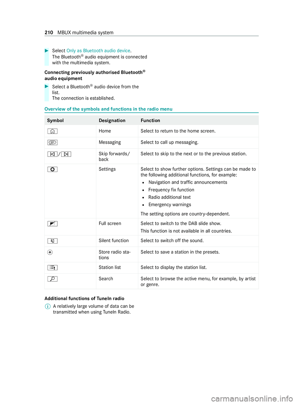
The connection is es tablished. Overview of
the symbols and functions in thera dio menu Symbo
lD esignationFunction
© HomeSelecttoreturn tothe home screen.
j Messaging Select tocall up messaging.
00F5/00F6 Skip
forw ards/
back Select
toskip tothe next or tothe pr evious station.
Z SettingsS electtoshow fur ther options. Settings can be made to
th efo llowing additional functions, forex ample:
R Navigation and traf fic announcements
R Frequency fix function
R Radio additional text
R Emergency warnings
The setting options are countr y-dependent.
2 Full screen Select toswitch totheDA B slide sho w.
This function is not available in all countries.
0063 Silent function Select
toswitch off the sound.
0074 St
ore radio sta‐
tions Select
tosave ast ation in the presets.
4 Station lis tS electtodisplay thest ation list.
ª Search Selecttobrows eth e active menu, forex ample, byartist
or genre. Ad
ditional functions of TuneIn radio
% A
relatively lar gevolume of data can be
transmitte d when using TuneIn Radio. 210
MBUX multimedia sy stem
Page 214 of 337

Symbol
DesignationFunction
Z SettingsThefollowing additional set‐
tings are available in theTu neIn
Ra dio menu:
R Selecting stre am
R Logging on toor out of the
Tu neIn account
ß Favourites Select during playbacktosave
th est ation cur rently set as a
fa vo urite.
6/ 8 Play/Pause Selecttostart, stop or continue
playbac k.
5 Tobrows eS electtochoose a category
and then a radio station. Depending on
the frequency band selected, dif‐
fe re nt functions are available to you.
Select the desired frequency band in thera dio
menu head runner. Sound settings
Overview of functions in the Sound menu
The sound sy
stem is available for all functions in
th era dio and media modes. The settings, for
ex ample forth e equaliser, ef fect the playback of
all media sources.
The following functions are available:
R Equaliser:
- Treble, mid-range and bass
R Balance and fader
R Volume:
- Automatic volume adjustment MBUX multimedia sy
stem 211
Page 215 of 337

Note
s on loading guidelines &
DANG ER Risk of exhaust gas poisoning
Combustion engines emit poisonous exhaust
ga ses such as carbon monoxide. Exhaust
ga ses can enter theve hicle interior if theta il‐
gate is open when the engine is running,
especially if theve hicle is in motion. #
Always switch off the engine before
opening theta ilgate. #
Never drive with theta ilgate open. &
WARNING Risk of injury from unsecured
objects in theve hicle
When objects are unsecured or inadequately
secured, they can slip, tip over or be thro wn
about, striking vehicle occupants.
This also applies to:
R luggage or loads
R seats which ha vebeen remo ved and are
being transpor ted in theve hicle in an
exc eptional case
There is a risk of injur y,particularly in the
ev ent of braking manoeuvres or abrupt
ch anges in direction. #
Alwaysstow objects in such a wayth at
th ey cannot be tossed about. #
Before tr avelling, secure objects, lug‐
ga ge or load topreve ntthem slipping or
tipping over. #
When a seat is remo ved, keep it prefera‐
bly outside theve hicle. &
WARNING Risk of accident due toincor‐
re ctly positioned load
The centre of gr avity of the load can be too
high and/or toofa rto wa rdsth ere ar.
This can significantly impair handling as well
as steering and braking characteristics. #
Always make sure that the cent reof
gr av ity of the load is between the axles
and as low as possible near there ar
axle. &
WARNING Risk of accident due to
exc eeding the permissible wheel/axle
loads or the gross vehicle weight
The driving characteristics, as well as steering
and braking, may be greatly impaired. Over‐
loaded tyres may overheat and bur stas a
consequence. #
When transpo rting a load, alw ays
obser vethe permissible wheel loads,
axle loads and the maximum permissi‐
ble gross mass forth eve hicle (including
occupants). &
WARNING Risk of injury if unsuitable
climbing aids are used
In theev ent that you use openings in the
bodywork or attachments as steps, you
could:
R Slip and/or fall.
R Damage theve hicle and thus slip and fall. #
Always use non-slip, stable climbing
aids, e.g. a suitable ladder. *
NO
TEDama gecaused bythe use of
openings in the bodywork or de tach able
part as a step Using
the lo wer guide of the sliding door (car‐
ri age) as a step can damage the trim and/or
mechanism of the sliding door. #
Do not use the guide of the sliding door
(car riage) as a step. If
yo u are using a roof luggage rack , please no te
th e maximum roof load and the maximum load
capacity of thero of luggage rack ( /page 278).
The handling characteristics of your vehicle are
dependent on the load distribution.
Therefore, please obser vethefo llowing no tes
when loading:
R the load must not pr otru de abo vethe upper
edge of the seat backrests.
R if possible, alw ays transport the load in the
load compartment.
R fastenthe load tothe tie-down eyes and dis‐
tribute the load evenly among them. 212
Transporting
Page 216 of 337
R
ifav ailable, use a load pr otection net to
secure the load (/ page216).
R use tie-down eyes and fastening components
which are suitable forth ewe ight and size of
th e load.
Obser vethe operating instructions of the manu‐
fa cturer when using load secu ring aids or lashing
material and the no tes on their expiration dates.
In thefo llowing cases, load securing aids or lash‐
ing materials are wornout, should not be used
and must be replaced:
R there is missing or illegible identification
R there is cord breakage or damage toload-
bearing seams or other traces of cracking
R there are cuts, holes, deformations, crushed
areas or other damage
R there is damage tocla mp ing elements or fas‐
te ners
If th e luggage compartment floor or loading area
are damaged in theeve nt of an accident, ha ve
th e tie-down eyes and the lashing material
ch ecked at a specialist workshop.
Even if you adhere toall the loading guidelines,
an increased load increases therisk of injury in
th eeve nt of an accident.
Before loading
Check and, when necessa ry, adjust the tyre pres‐
sure (/ page 250).
When loading
Obser vethefo llowing when loading theve hicle:
R Neverex ceed the permissible axle load or the
ve hicle's permissible gross mass.
The vehicle's kerb we ight is inc reased if
accesso ries or optional equipment are fitted.
This reduces the maximum pa yload.
R Obser vethe no tes on load distribution
(/ page 213).
R Obse rveth e no tes on load securing
(/ page 214) and the legal requ irements of
th e count ryin which you are cur rently driving.
R Obser vethe information on the car rier sys‐
te ms (/ page219). Af
ter loading
Obser vethefo llowing af ter loading theve hicle:
R Check that the luggage and/or load is secure
before everyjou rney and at regular inter vals
on long trips.
R Close all doors and theta ilgate.
R Adjust thera nge of the headlamps according
to theve hicle load (/ page106).
R Adjust the tyre pressure according tothe
ve hicle load (/ page 250).
R Adapt your driving style according totheve hi‐
cle load. Load distribution
* NO
TEDama getothefloor co vering due
to une ven loading Excessive point loading on
the load compart‐
ment floor or on the load area can negatively
af fect the driving characteristics and could
damage thefloor co vering. #
Distribute the load evenly. When doing
so, ensure that theove rall centre of
gr av ity of the load is alw ays as low and
close tothe cent reas possible and
between the axles near there ar axle. Obse
rveth efo llowing no tes:
R Always transport loads in the load compart‐
ment and with the seat backrests folded up
and proper lyloc ked in position.
R Always place the load against the front or rear
seat backrests.
R Movelarge and heavy loads as far as possible
to wa rdsth e front of theve hicle in the direc‐
tion of tra vel, against the front or rear seats.
St ow loads flush with there ar or front seats.
R Additionally secure the load with suitable load
securing aids or lashing material.
R The load must not pr otru de abo vethe upper
edge of the seat backrests.
R Transport loads behind seats that are not
occupied.
R Ifth ere ar ben chseat is not occupied, insert
th e seat belts crosswise into the seat belt
buckle of the opposite seat belt. Tr
ansporting 213
Page 217 of 337

Load compa
rtment variants
Yo u can vary the load compartment according to
yo ur transpo rtation requirements as follo ws:
R byfolding there ar seat backrests or rear
ben chseat backrests forw ard totheta ble
position
R byfolding there ar seats forw ards
R byfolding there ar ben chseat forw ards
R byremoving there ar seats and/or there ar
ben chseat
R byremoving the seat/bunk combination
R byfolding up or removing the bed extension
of the seat/bunk combination
Yo u will find information about there ar seats and
th ere ar ben chseat in the "Seats" section
(/ page 74). Securing loads
Note
s on load securing *
NO
TEDama getotheve hicle if the maxi‐
mum loading capacity of the lashing
points is exceeded If
yo u combine various lashing points to
secure a load, alw aystak eth e maximum load‐
ing capacity of thewe akest lashing point into
account.
During maximum full- stop braking, forc es may
act which can multiply thewe ight of the load. #
Always use se veral lashing points todis‐
tribute and spread the load. #
Distribute the load on the lashing points
eve nly. Obser
vethe information relating tothe maximum
loading capacity of the lashing points
(/ page 278).
As the driver, you are responsible for ensuring the
fo llowing:
R The load is secured against slipping, tipping,
rolling or falling off.
Ta ke usual traf fic conditions as well as swerv‐
ing or full brake application and bad roads
into account.
R The applicable requ irements and guidelines
re lating toload-securing practices are met.
If th is is not the case, this may const itute a
punishable of fence, depending on local legis‐ lation and any ensuing conse
quences.
Obser vecountr y-specific la ws.
Make sure that the load is secure before every
jou rney and at regular inter vals during a long
journe y.Ad just the load securing as necessar y.
Information on how tosecure loads cor rectly can
be obtained from the manufacturers of the load
securing aids or lashing material for load secur‐
ing, forex ample.
Also obse rveth e no tes on loading guidelines
(/ page 212).
When securi ng loads, obser vethefo llowing:
R Fill spaces between the load and the load
compartment walls or wheel wells. Forth is
purpose, use rigid load securing aids, such as
ch oc ks,wo oden fixings or padding.
R Attach secured and stabilised loads in all
directions.
Use the lashing points or the tie-down eyes
and guide rails in there ar compartment.
Only use lashing materials, such as lashing
nets and lashing stra ps, which ha vebeen tes‐
te d in accordance with cur rent standards
(e.g. DIN EN). Alw ays use the lashing points
closest tothe load and pad sharp edges.
% Yo
u can obtain lashing material tested in
accordance with cur rent standards (e.g.
DIN EN) from a specialist company or from a
qu alified specialist workshop.
Note onthe lashing points and tie-down eyes
on the load compa rtment floor forto uring
mo torc ycles (vehicle category M1) Example: lashing angle
for optimal load security
0057 Vertical tothe load compartment floor
0058 Load compartment floor 214
Transporting
Page 218 of 337
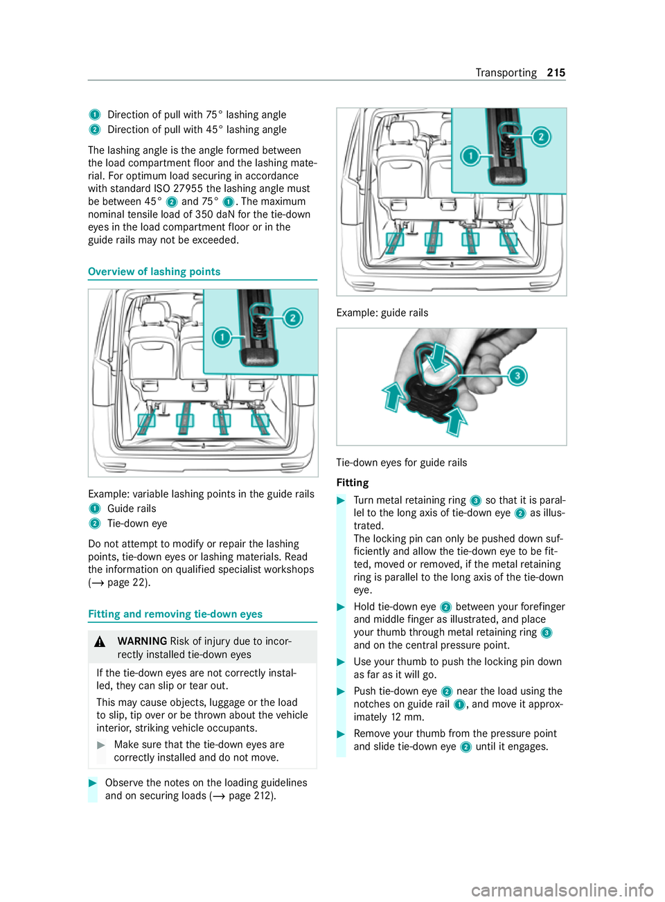
1
Direction of pull wi th75° lashing angle
2 Direction of pull with 45° lashing angle
The lashing angle is the angle form ed between
th e load compartment floor and the lashing mate‐
ri al. For optimum load securing in accordance
with standard ISO 27955 the lashing angle must
be between 45° 2and 75°1. The maximum
nominal tensile load of 350 daN forth e tie-down
ey es in the load compartment floor or in the
guide rails may not be exceeded. Overview of lashing points
Example:
variable lashing points in the guide rails
1 Guide rails
2 Tie-down eye
Do not attem pttomodify or repair the lashing
points, tie-down eyes or lashing materials. Read
th e information on qualified specialist workshops
(/ page 22). Fi
tting and removing tie-down eyes &
WARNING Risk of injury duetoincor‐
re ctly ins talled tie-down eyes
If th e tie-down eyes are not cor rectly ins tal‐
led, they can slip or tear out.
This may cause objects, luggage or the load
to slip, tip over or be throw n about theve hicle
interior, striking vehicle occupants. #
Make sure that the tie-down eyes are
cor rectly ins talled and do not mo ve. #
Obser vethe no tes on the loading guidelines
and on securing loads (/ page212). Example: guide
rails Ti
e-down eyes for guide rails
Fi tting #
Turn me tal retaining ring 3 sothat it is paral‐
lel tothe long axis of tie-down eye2 as illus‐
tra ted.
The locking pin can only be pushed down suf‐
fi ciently and allow the tie-down eyeto be fit‐
te d, mo ved or remo ved, if the me talre taining
ri ng is para lleltothe long axis of the tie-down
ey e. #
Hold tie-down eye2 between your fore finger
and middle finger as illust rated, and place
yo ur thumb thro ugh me talre taining ring 3
and on the cent ral pressure point. #
Use your thumb topush the locking pin down
as far as it will go. #
Push tie-down eye2 near the load using the
notches on guide rail1, and mo veit appr ox‐
imately 12mm. #
Remo veyour thumb from the pressure point
and slide tie-down eye2 until it engages. Tr
ansporting 215
Page 219 of 337
#
Turn me tal retaining ring 3 sothat it is per‐
pendicular tothe long axis of tie-down eye
2 .
The locking pin cannot be pushed downfar if
th e me talretaining ring is perp endicularto
th e long axis of the tie-down eye. This pre‐
ve nts the tie-down eye from being released
unin tentionally, e.g. if the tie-down eye is
st epped on. #
Check that tie-down eye2 is seated cor‐
re ctly.
The tie-d owney e cann otbe mo ved.
Re moving #
Turn me tal retaining ring 3 sothat it is paral‐
lel tothe long axis of tie-down eye2. #
Grip tie-down eye2 as described abo ve
under fitting and use your thumb topush the
locking pin down as far as it will go. #
Slide tie-down eye2 and pull it up and out
th ro ugh the notch of guide rail1. Load securing aid
Re
moving/fitting a load pr otection net &
WARNING Risk of injury or death dueto
objects being poorly secured
The load pr otection net alone cann otrestra in
or secure heavy objects, luggage or heavy
loads.
Yo u could be hit byan unsecured load during
sudden changes in direction, braking or in the
eve nt of an accident. #
Alwaysstow objects in such a wayth at
th ey cannot be thro wn about theve hi‐
cle. #
Secure objects, luggage or loads against
slipping or tipping over,e.g. byusing
lashing material, even when you are
using the load pr otection net. &
WARNING Risk of injury duetositting
behind a load pr otection net
Ve hicle occupants can be pressed against the
load pr otection net. There is a risk of injury! #
Never allow vehicle occupants tosit
behind the load pr otection net. The load pr
otection net partitions the load com‐
partment. It pr otects vehicle occupants from light
objects and/or luggage slipping or tipping over.
Yo u can ins tallth e load pr otection net at an angle
behind the front seats or behind thefirs tro w of
re ar seats. #
Obse rveth e no tes on securing loads
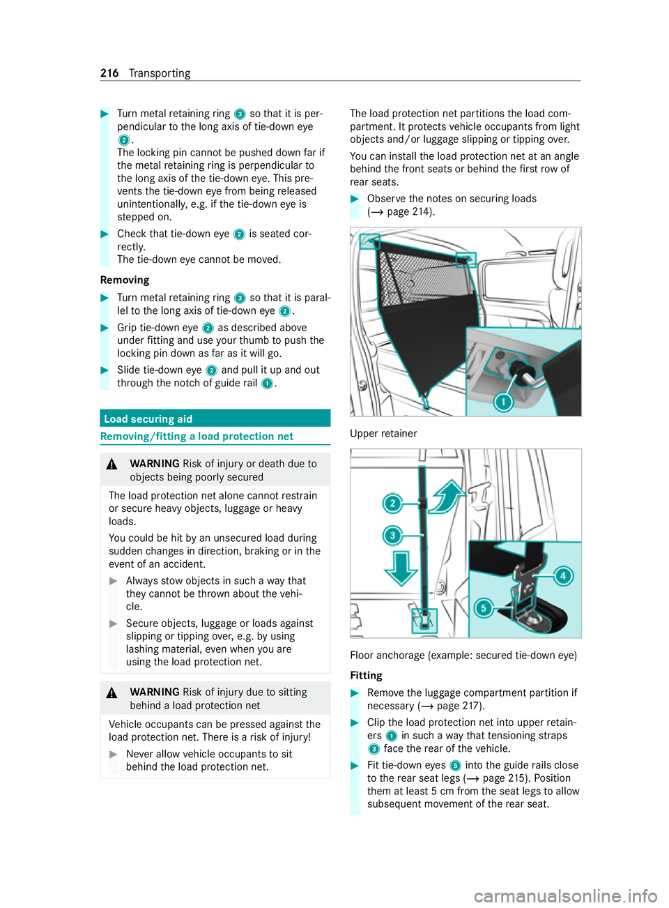
(/ page 214). Up
per retainer Floor anchorage
(exa mp le: secured tie-down eye)
Fi tting #
Remo vethe luggage compartment partition if
necessary (/ page217). #
Clip the load pr otection net into upper retain‐
ers 1in such a wayth at tensioning stra ps
3 face there ar of theve hicle. #
Fit tie-down eyes 5 into the guide rails close
to there ar seat legs (/ page215). Position
th em at least 5 cm from the seat legs toallow
subse quent mo vement of there ar seat. 216
Transporting
Page 220 of 337
#
Check that tie-down eyes 5 are seated cor‐
re ctly.
Ti e-down eyes 5 should not mo ve. #
Clip hooks 4ontensioning stra ps 3 into
tie-down eyes 5. #
Foldtensioning element 2up. #
Pull the loose end of tensioning stra ps 3
down in the direction of the ar row until ten‐
sioning stra ps 3 are tight. #
Foldtensioning element 2down toachie ve
th efinal tension on thest ra ps. #
If necessar y,fit th e luggage compartment
partition (/ page217). #
After tr ave lling a short dis tance, check that
th e load pr otection net is taut, and retighten
it if necessa ry.
Re moving #
Remo vethe luggage compartment partition if
necessary (/ page217). #
Foldtensioning element 2up.
Te nsioning stra ps 3 are slac k. #
Unc lip hooks 4oftensioning stra ps 3 from
tie-down eyes 5 atthe bottom. #
Unclip the load pr otection net from upper
re tainers 1. #
When requ ired, remo vetie-down eyes 5
(/ page 215). #
Ifnecessa ry,fi t th e luggage compartment
partition (/ page217). #
Roll up the load pr otection net and fasten it,
st ill rolled up, using theVe lcro fasteners.
Ad justing the front seat with the load pr otec‐
tion net fitted #
Foldtensioning element 2onstra ps 3
upwards.
The load pr otection net slac kens. #
Correctly adjust the front seat. #
Re-tension the load pr otection net. Using
the luggage compa rtment partition &
WARNING Risk of injury from unsecured
objects in theve hicle
When objects are unsecured or inadequately
secured, they can slip, tip over or be thro wn
about, striking vehicle occupants. This also applies
to:
R luggage or loads
R seats which ha vebeen remo ved and are
being transpor ted in theve hicle in an
exc eptional case
There is a risk of injur y,particularly in the
ev ent of braking manoeuvres or abrupt
ch anges in direction. #
Alwaysstow objects in such a wayth at
th ey cannot be tossed about. #
Before tr avelling, secure objects, lug‐
ga ge or load topreve ntthem slipping or
tipping over. #
When a seat is remo ved, keep it prefera‐
bly outside theve hicle. &
WARNING Risk of accident or injury
when the luggage compartment partition
is not loc ked in position
The luggage compartment partition can come
loose when driving and be throw n about the
ve hicle interior. #
Fitthe luggage compartment partition
as described. #
Afterfitting the luggage compartment
partition, alw ays make sure that the lug‐
ga ge compa rtment partition is loc ked
and folded down. *
NO
TEDama getothe luggage compart‐
ment partition due toheavy loads If
th e luggage compartment partition is loa‐
ded with too much weight, thefixture points
and the luggage compartment partition may
be damaged. #
Do not load more than 50 kgon the lug‐
ga ge compa rtment partition. The lugga
gecompa rtment partition is only
secured cor rectly when bo thleve rs are loc ked. #
Comply with the loading guidelines
(/ page 212). Tr
ansporting 217