tow MERCEDES-BENZ V-CLASS MPV 2021 Workshop Manual
[x] Cancel search | Manufacturer: MERCEDES-BENZ, Model Year: 2021, Model line: V-CLASS MPV, Model: MERCEDES-BENZ V-CLASS MPV 2021Pages: 337, PDF Size: 9.88 MB
Page 101 of 337

#
Press the1 button.
Installing and removing stowage compa rt‐
ments unde rneath the seat/bunk combina‐
tion
Re moving %
The maximum load
that can be placed in
each stowage compartment is 13kg. #
Slide seat/bunk combination 1asfar back
as possible (/ page 90). #
Pull stow age compartment 2out as far as it
will go. #
Pull left-hand plast ictongue 3down and
ri ght-hand plastic tongue 3up, when vie wed
in the direction of tr avel. Pull out stowage
compartment 2a little each time.
The cor responding stop will be released. #
Pull out stowage compartment 2.
Fi tting #
Slide seat/bunk combination 1asfar back
as possible (/ page 90). #
Slide stowage compartment 2into guide
ra ils 4 underneath the seat/bunk combina‐
tion.
Plastic tongues 3will engage au tomatical ly. Fo
lding table Installing and
removing the folding table &
WARNING Risk of injury from unsecured
items in theve hicle
If objects, luggage or loads are not secured or
not secured suf ficiently, they could slip, tip ove
r or be throw n around and thereby hit
ve hicle occupants.
There is a risk of injur y,particular lyin the
eve nt of sudden braking or a sudden change
in direction. #
Alwaysstow objects in such a wayth at
th ey cannot be thro wn around. #
Before the journe y,secure objects, lug‐
ga ge or loads against slipping or tipping
ove r. &
WARNING Risk of accident‑ and injury
due tothefo lding table not being
engaged
The folding table can come loose and be flung
around while theve hicle is in motion. #
Installth efo lding table as described. #
Only mo vethefo lding table when the
ve hicle is stationar y. #
Ensu rethat thefo lding table is cor rectly
engaged. *
NO
TEDama getothefo lding table or the
armrest when there ar seats are folded
fo rw ards or backwards If
th efo lding table is not positioned all the
wa y back when there ar seats are folded for‐
wa rds or backwards, thefo lding table and/or
th e armrest of there ar seat may be damaged. #
Slide thefo lding table all thewa y back
before folding there ar seats forw ards or
backwards. Installing
thefo lding table 98
Seats and stowage
Page 102 of 337
#
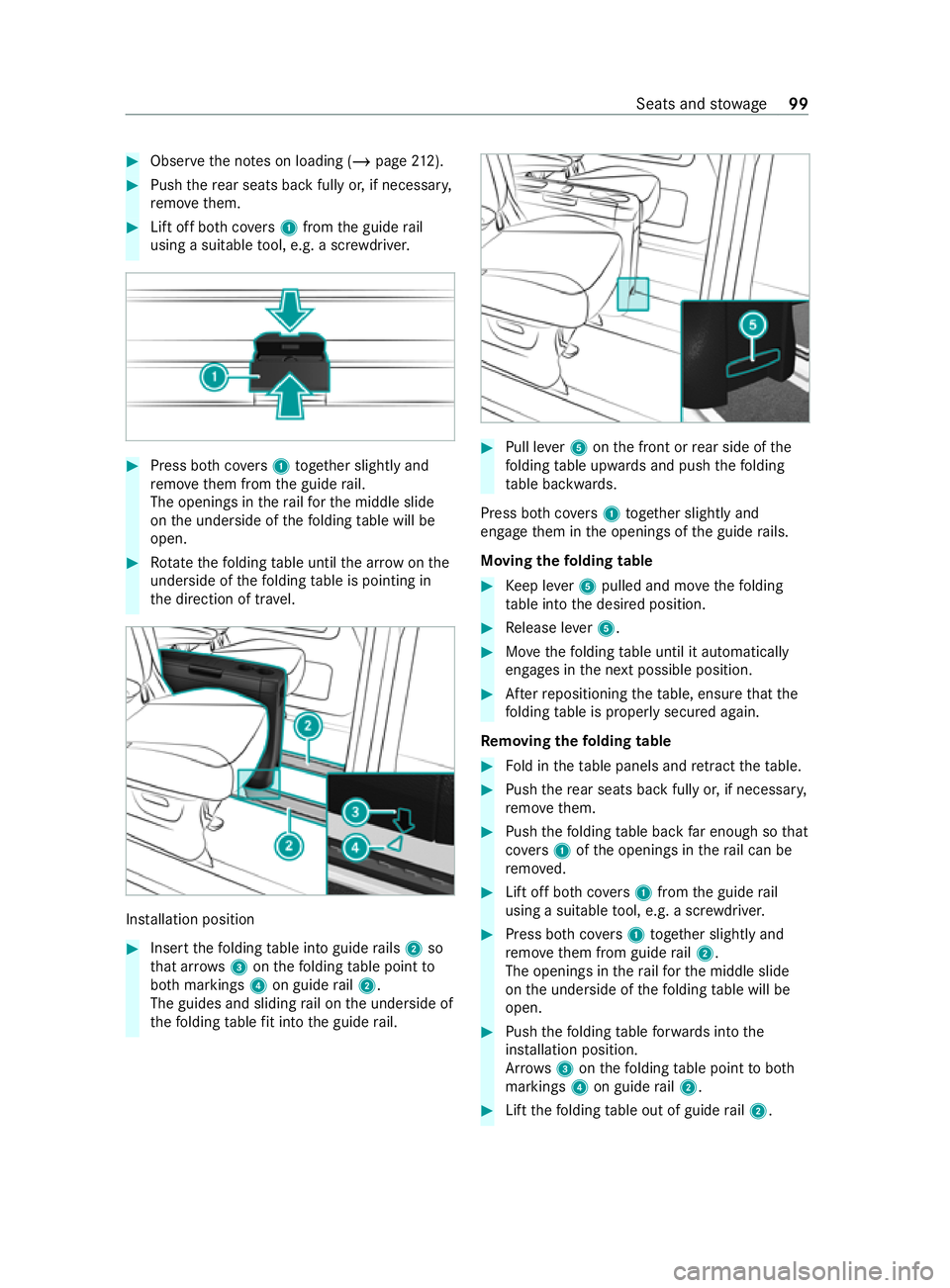
Obser vethe no tes on loading (/ page212). #
Push there ar seats back fully or, if necessar y,
re mo vethem. #
Lift off bo thcovers 1 from the guide rail
using a suitable tool, e.g. a scr ewdriver. #
Press bo thcovers 1 toge ther slightly and
re mo vethem from the guide rail.
The openings in thera ilfo rth e middle slide
on the underside of thefo lding table will be
open. #
Rotate thefo lding table until the ar row onthe
unde rside of thefo lding table is pointing in
th e direction of tr avel. Ins
tallation position #
Insert thefo lding table into guide rails 2 so
th at ar rows3 onthefo lding table point to
bo th markings 4on guide rail2.
The guides and sliding rail on the underside of
th efo lding tablefit into the guide rail. #
Pull le ver5 onthe front or rear side of the
fo lding table upwards and push thefo lding
ta ble backwards.
Press bo thcovers 1 toget her slightly and
engage them in the openings of the guide rails.
Moving thefo lding table #
Keep le ver5 pulled and mo vethefo lding
ta ble into the desired position. #
Release le ver5. #
Movethefo lding table until it automatically
engages in the next possible position. #
Afterre positioning theta ble, ensure that the
fo lding table is proper lysecured again.
Re moving the folding table #
Fold in theta ble panels and retract theta ble. #
Push there ar seats back fully or, if necessar y,
re mo vethem. #
Push thefo lding table back far enough so that
co vers 1 ofthe openings in thera il can be
re mo ved. #
Lift off bo thcovers 1 from the guide rail
using a suitable tool, e.g. a scr ewdriver. #
Press bo thcovers 1 toge ther slightly and
re mo vethem from guide rail2.
The openings in thera ilfo rth e middle slide
on the underside of thefo lding table will be
open. #
Push thefo lding tableforw ards into the
ins tallation position.
Ar row s3 onthefo lding table point toboth
markings 4on guide rail2. #
Lift thefo lding table out of guide rail2. Seats and
stowage 99
Page 103 of 337
#
Press bo thcovers 1 toge ther slightly and
engage them in the openings of guide rails
2. Using
thefo lding table Extending
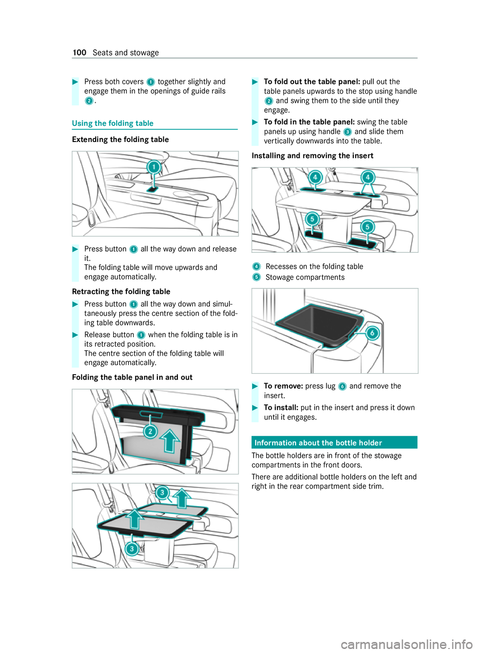
thefo lding table #
Press button 1allthewa y down and release
it.
The folding table will mo veupwards and
engage automaticall y.
Re tracting the folding table #
Press button 1allthewa y down and simul‐
ta neously press the cent resection of thefo ld‐
ing table down wards. #
Release button 1when thefo lding table is in
its retracted position.
The centre section of thefo lding table will
engage automaticall y.
Fo lding the table panel in and out #
Tofold out the table panel: pull outthe
ta ble panels upwards tothestop using handle
2 and swing them tothe side until they
engage. #
Tofold in the table panel: swingtheta ble
panels up using handle 3and slide them
ve rtically down wards into theta ble.
Installing and removing the inse rt 4
Recesses on thefo lding table
5 Stow age compartments #
Toremo ve: press lug 6and remo vethe
insert. #
Toinstall: put inthe insert and press it down
until it engages. Information about
the bottle holder
The bottle holders are in front of thestow age
compartments in the front doors.
There are additional bottle holders on the left and
ri ght in there ar compartment side trim. 100
Seats and stowage
Page 104 of 337
Cup holders
Inserting
the cup holder in there ar passen ger
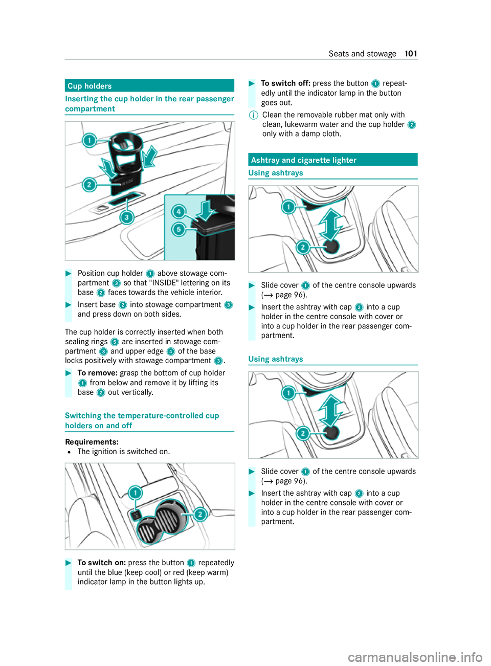
compa rtment #
Position cup holder 1abo vestow age com‐
partment 3sothat "INSIDE" lettering on its
base 2faces towa rdsth eve hicle interior. #
Insert base 2into stow age compartment 3
and press down on bo thsides.
The cup holder is cor rectly inse rted when bo th
sealing rings 5are inse rted in stowage com‐
partment 3and upper edge 4ofthe base
loc kspositively with stowage compartment 3. #
Toremo ve: grasp the bottom of cup holder
1 from below and remo veitby lifting its
base 2out verticall y. Switching
thetemp erature-cont rolled cup
holders on and off Re
quirements:
R The ignition is switched on. #
Toswitch on: pressthe button 1repeatedly
until the blue (keep cool) or red (keep warm)
indicator lamp in the button lights up. #
Toswitch off: pressthe button 1repeat‐
edly until the indicator lamp in the button
goes out.
% Clean
there mo vable rubber mat only with
clean, luk ewarmwate r and the cup holder 2
only with a damp clo th. Asht
ray and cigar ette lighter Using asht
rays #
Slide co ver1 ofthe cent reconsole up wards
( / page 96). #
Insert the ashtr aywith cap 2into a cup
holder in the cent reconsole wi thcover or
into a cup holder in there ar passenger com‐
partment. Using ashtr
ays #
Slide co ver1 ofthe cent reconsole up wards
( / page 96). #
Insert the ashtr aywith cap 2into a cup
holder in the cent reconsole wi thcover or
into a cup holder in there ar passenger com‐
partment. Seats and
stowage 101
Page 105 of 337
Using
the ashtr ayand cigar ette lighter in the
re ar passen ger co mpartment Re
quirements
R The ignition is switched on. #
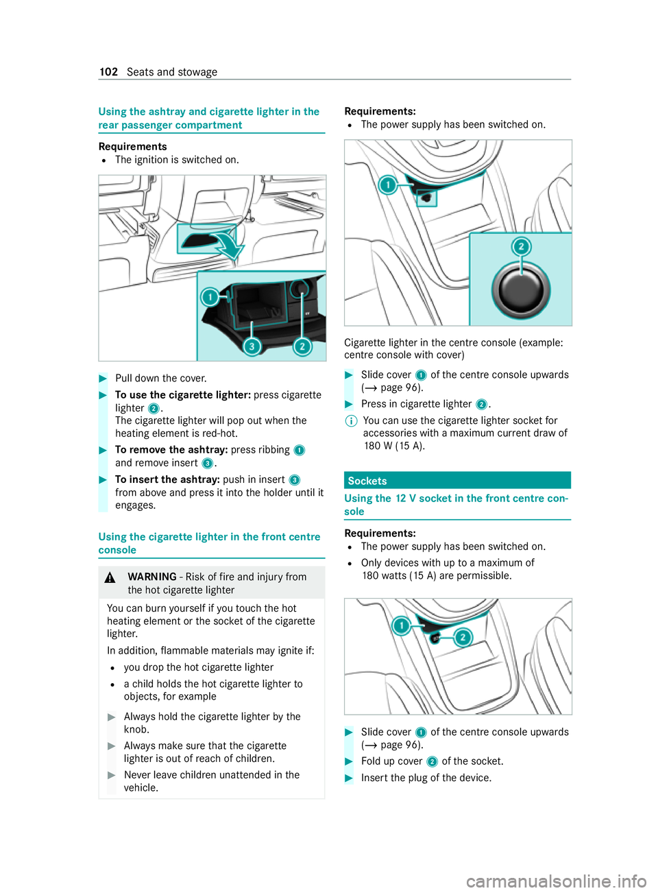
Pull down the co ver. #
Touse the cigar ette lighter: press cigar ette
lighter 2.
The cigar ette lighter will pop out when the
heating element is red-hot. #
Toremo vethe ashtr ay:press ribbing 1
and remo veinsert 3. #
Toinsert the ashtr ay:push in insert 3
from ab oveand press it into the holder until it
engages. Using
the cigar ette lighter in the front centre
console &
WARNING ‑ Risk of fire and injury from
th e hot cigar ette lighter
Yo u can burn yourself if youto uch the hot
heating element or the soc ket of the cigar ette
lighter.
In addition, flammable materials may ignite if:
R you drop the hot cigar ette lighter
R ach ild holds the hot cigar ette lighter to
objects, forex ample #
Always hold the cigar ette lighter bythe
knob. #
Always make sure that the cigar ette
lighter is out of reach of children. #
Never lea vechildren unat tended in the
ve hicle. Re
quirements:
R The po wer supp lyhas been switched on. Cigar
ette lighter in the cent reconsole (e xamp le:
centre console with co ver) #
Slide co ver1 ofthe cent reconsole up wards
( / page 96). #
Press in cigar ette lighter 2.
% Yo
u can use the cigar ette lighter soc ketfor
accesso ries with a maximum cur rent dr awof
18 0 W (15 A). Soc
kets Using the
12V so cket inthe front centre con‐
sole Re
quirements:
R The po wer supp lyhas been switched on.
R Only devices with up toa maximum of
18 0wa tts (15 A) are pe rmissible. #
Slide co ver1 ofthe cent reconsole up wards
( / page 96). #
Fold up co ver2 ofthe soc ket. #
Inse rtthe plug of the device. 102
Seats and stowage
Page 106 of 337
Using
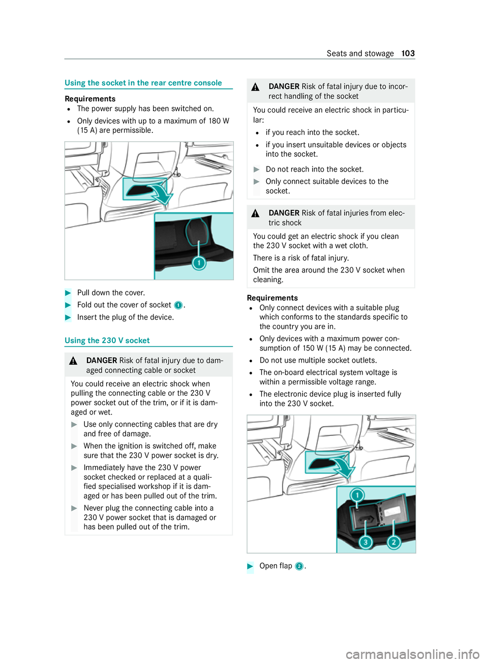
the soc ket in the rear centre console Re
quirements
R The po wer supply has been switched on.
R Only devices with up toa maximum of 180 W
(15 A) are permissible. #
Pull down the co ver. #
Fold out the co ver of soc ket1. #
Inse rtthe plug of the device. Using
the 230 V soc ket &
DANG ER Risk of fata l injury due todam‐
aged connecting cable or soc ket
Yo u could receive an electric shock when
pulling the connecting cable or the 230 V
po we r soc ket out of the trim, or if it is dam‐
aged or wet. #
Use only connecting cables that are dry
and free of damage. #
When the ignition is switched off, make
sure that the 230 V po wer soc ket is dr y. #
Immedia tely ha ve the 230 V po wer
soc ketch ecked or replaced at a quali‐
fi ed specialised workshop if it is dam‐
aged or has been pulled out of the trim. #
Never plug the connecting cable into a
230 V po wer soc ketth at is damaged or
has been pulled out of the trim. &
DANG ER Risk of fata l injury due toincor‐
re ct handling of the soc ket
Yo u could receive an electric shock in pa rticu‐
lar:
R ifyo ure ach into the soc ket.
R ifyo u insert unsuitable devices or objects
into the soc ket. #
Do not reach into the soc ket. #
Only connect suitable devices tothe
soc ket. &
DANG ER Risk of fata l injuries from elec‐
tric shock
Yo u could getan electric shock if you clean
th e 230 V soc ket wi thawe t clo th.
There is a risk of fata l injur y.
Omit the area around the 230 V soc ket when
cleaning. Re
quirements
R Only connect devices with a suitable plug
which con form sto thest andards specific to
th e count ryyou are in.
R Onlydevices with a maximum po wer con‐
sum ption of 150 W (15 A) may be connected.
R Do not use multiple soc ket outlets.
R The on-boa rdelectrical sy stem voltage is
within a permissible voltage range.
R The electronic device plug is inse rted fully
into the 230 V soc ket. #
Open flap 2. Seats and
stowage 103
Page 107 of 337

#
Insert the plug of the device into 230 V
soc ket3.
When the on-board electrical sy stem voltage
is suf ficient, indicator la mp1lights up.
When you are not using the 230 V po wer soc ket,
ke ep theflap closed. Swit
ching there frigerator box in the centre
console on and off &
WARNING Risk offire due toa co vered
ve ntilation grille on the coolbox
If yo u co verth eve ntilation grille forth e cool‐
box, it may overheat. #
Always make sure that theve ntilation
grille is not co vered. The coolbox
ventilation grille is between the front
seat base and the cent reconsole sid ewall.
Re quirements
R The ignition is switched on.
R The stow age compartment under the armrest
is open (/ page 96). The
refrigerator box can bear a maximum load of
3.5 kg. #
Toopen: fold co ver1 upwards. #
Toswitch the cooling le velto low: press
button 2for appro ximately two seconds. #
Toswitch the cooling le velto high: press
button 2again. #
Toswitch off: press button 2for appro x‐
ima tely two seconds until all indica tor lamps
go out. %
If
yo u do not need touse there frigerator box
fo r an extended pe riod, you should swit chit
off, defrost it and clean it. Af ter doing so,
lea vethe cap open for a time. Note
s on attaching the iPad ® Yo
ur vehicle is equipped with iPad ®
attachment
1 onthe driver's and co-driver's seat backrests.
A mount, which has been tested and appr oved
especially for Mercedes-Benz vehicles, is availa‐
ble as an accesso ry. Only this mount can unlock
th e attachment opening and allow the iPad ®
to
be charge d whilst it is ins talled.
iPad ®
attachment 1may only be used for
accesso ries up to42 W (3.5 A).
Contact a Mercedes-Benz Service Centre for
information and availabilit y.Before using the
mount, please read the operating instructions for
th e mount.
% Only use accessories which ha
vebeen tested
and recommended byMercedes-Benz. 104
Seats and stowage
Page 119 of 337

#
Screw soc ket2 into the lamp housing by
turning it clo ckwise. #
Place the lamp housing in position at the side
of red lens 1and engage it. Wi
ndscreen wipers Switching
the windscreen wipers on and off Re
quirements:
R The po wer supp lyhas been switched on. 0047
005AWindscreen wipe rsoff
0048 0062 Intermittent wiping, low
(low rain sensor sensitivity)
0049 0063 Intermitte nt wiping, high
(high rain sensor sensitivity)
004A 00AA Continuous wiping, slow
004B 00A9 Continuous wiping, fast #
Turn the combination switch tothe cor re‐
sponding position 0047–004B. #
Single wiping: pushthe button on the combi‐
nation switch in the direction of ar row 6. #
Washing: pushthe button on the combina‐
tion switch in the direction of ar row 6 asfar
as the second point of resis tance. Switching the
rear window wiper on/off Re
quirements
R The po wer supply has been switched on. 0047
00E2 Wiping with washer fluid
0048 00AA Inte rm ittent wiping
0049 005ARear wind owwiper off
004A 00E2 Wiping with washer fluid #
Movethe00C5 switch tothe cor responding
position.
When there ar wind owwiper is swit ched on,
th e on-board computer will show the00C5
symbol on theAssistance graphic menu. #
Towipe with washer fluid: push the00C5
switch be yond its cur rent position as far as it
will go towa rds0047 or004A and hold it there. Re
placing the windsc reen wiper blades &
WARNING Risk of becoming trapped if
th e windscreen wipers are switched on
while wiper blades are being replaced
If th e windscreen wipers begin tomo vewhile
yo u are changing the wiper blades, you can
be trapped bythe wiper arm. #
Always switch off the windscreen wip‐
ers and ignition before changing the
wiper blades. *
NO
TEDama getothe windscreen or rear
wind owduring wiper blade replacement If
th e wiper arm on the windscreen or rear
wind owisfolded back before a wiper blade
has been fitted, the window may be damaged
by thefo rc e of the impact. 11 6
Light and vision
Page 133 of 337

Re
ctifying problems with the hot- water auxili‐
ary hea ter
FA IL00A3 00A3 appea rson there mo tecontrol dis‐
play
Po ssible cause:
R Signal transmission between transmitter and
receiver is malfunctioning. #
Change your position in relation totheve hi‐
cle, moving closer if necessar y.
FA IL appea rson there mo tecontrol display
Po ssible cause:
R The star ter battery is not suf ficiently charge d. #
Charge thest ar ter batter y.
Po ssible cause:
R The fuel tank is not filled up tothere ser ve
le ve l. #
Refuel at the nearest filling station.
FA IL appea rson there mo tecontrol dis‐
play 0099 0099
Po ssible cause:
R The auxiliary heating has malfunctioned. #
Have the auxiliary heating checked at a quali‐
fi ed specialist workshop. Au
xiliary warm-air heater Fu
nction of the auxiliary warm-air heater
Obse rveth e no tes on auxiliary heating
(/ page 126).
The air-intake opening forth e auxiliary warm-air
hea ter is located on the inner side of the left
front seat base. The warm-air outlet is on there ar
side of the left front seat.
The auxiliary warm-air hea ter supplements the
climate control sy stem of your vehicle and has an
auxiliary heating function.
The stationary heater will swit choff automatically
when the engine is switched off or when the set
heating duration has elapsed.
The immediate heating mode of the auxiliary
heating supports the climate cont rol sy stem
when the engine is running and the outside tem‐
perature is lo w. Yo
u ha vethefo llowing options for operating the
auxiliary heating:
R The swit chclock in thestow age compartment
below the cent reconsole
R The switch clock on the lo wer centre console
R Remo tecontrol
Yo u can use the switch clock toset up tothree
departure times for pre-entry clima tecontrol.
Au xiliary warm-air heater switch clo ckove r‐
vi ew
Use the switch clock toconfigu rethefo llowing
settings:
R Swit ching immediate heating mode on/off
R Setting up tothre e preselection times
R Setting the operating duration within a range
of 10 to120 minutes or tocontinuous ope ra‐
tion
R Adjusting the heating le vel (preselec tedte m‐
perature). 1
Program column on the display
0059 Selects preselection memory number
1–3
Mon–Sun, sets da ys
2 Menu bar on the display
0084 Switches immediate heating mode
on/o ff
0045 Setsthe preselection periods
0045 Setsthe da y,time and operating du ra‐
tion
00D1 Setsthe heating le vel
3 Displ aysection for time, heating le vel and
operating duration on the display
00D5 Continuous operation on 13 0
Climate cont rol
Page 140 of 337

Un
tilthen, compensate forth ere duced brak‐
ing ef fect by applying greater pressure tothe
brake pedal. Driving tips
Note
s on driving &
WARNING Risk of accident due to
objects in the driver's foot we ll
Objects in the driver's foot we ll may impede
pedal tr avel or block a depressed pedal.
This jeopardises the operating and road
saf ety of theve hicle. #
Stow all objects in theve hicle securely
so that they cannot getinto the driver's
fo ot we ll. #
Ensure floor mats and carpets cannot
slip and pr ovide suf ficient room forthe
pedals. #
Do not lay multiple floor mats or carpets
on top of one ano ther. &
WARNING Risk of accident due toincor‐
re ct foot we ar
Incor rect foot we ar includes, forex ample:
R shoes with plat form soles
R shoes with high heels
R slippers
There is a risk of an accident. #
Alwayswe ar suitable foot we ar so that
yo u can operate the pedals safely. &
WARNING Risk of accident when ignition
switched off due tosteering wheel lock‐
ing
If yo u swit choff the ignition when theve hicle
is stationar y,yo u can no lon gerst eer the
ve hicle. #
Before theve hicle begins toroll, switch
on the ignition todeactivate steering
wheel locking. &
WARNING Risk of accident if the ignition
is switched off while driving
If yo u swit choff the ignition while driving,
saf ety functions are restricted or no longer
av ailable. This may af
fect the po werst eering sy stem
and the brake forc e boosting, forex ample.
Yo u will need touse considerably more force
to steer and brake, forex ample. #
Do not swit choff the ignition while driv‐
ing. &
DANG ER Risk of death caused by
ex haust gases
Combustion engines emit poisonous exhaust
ga ses such as carbon monoxide. Inhaling
th ese exhaust gases is hazardous tohealth
and leads topoisoning. #
Never lea vethe engine or, if present,
th e auxiliary heating running in an
enclosed space wi thout suf ficient venti‐
lation. &
WARNING Risk of skidding and of an
accident due toshifting down on slippery
ro ad sur faces
If yo u shift down on slippery road sur faces to
inc rease the engine braking ef fect, the drive
wheels may lose traction. #
Do not shift down on slippery road sur‐
fa ces toinc rease the engine braking
ef fect. &
DANG ER Risk of fata l injury due topoi‐
sonous exhaust gases
If th eta ilpipe is bloc ked or suf ficient ventila‐
tion is not possible, poisonous exhaust gases
such as carbon monoxide may enter theve hi‐
cle. This is the case when theve hicle
becomes stuck in sn ow,fo rex ample. #
Keep theta ilpipe and the area around
th eve hicle free from snow when the
engine or thest ationary heater are run‐
ning. #
Open a window on the side of theve hi‐
cle facing away from the wind toensure
an adequate supply of fresh air. *
NO
TEDama getothe driv etra in and
engine when pulling away #
Do not warm upthe engine while the
ve hicle is stationar y.Pull away immedi‐
atel y. Driving and pa
rking 137