wheel Mercury Mountaineer 1997 Owner's Manuals
[x] Cancel search | Manufacturer: MERCURY, Model Year: 1997, Model line: Mountaineer, Model: Mercury Mountaineer 1997Pages: 197, PDF Size: 2.08 MB
Page 2 of 197

The following icons appear in this
Owner's Guide:
indicates a warning. Read the
following section onWarningsfor
a full explanation of warnings.
indicates that vehicle
information related to recycling
and other environmental concerns
will follow.
Warnings
Warnings remind you to be
especially careful in those areas
where carelessness can cause
damage to your vehicle or personal
injury to yourself, your passengers
or other people. Please read all
Warnings carefully.
Notice to owners of utility-type
vehicles
As with other vehicles of this type,
failure to operate this vehicle
correctly may result in loss of
control or an accident. Be sure to
readSpecial driving instructions
for AWD vehicleslater in this
Owner's Guide and the special
supplement included with AWD
and 4x4 vehicles entitled
Four-Wheeling.
Four-Wheelingpresents safe
driving practices to owners of AWD
and 4x4 utility vehicles. Your AWD
vehicle handles differently than an
ordinary passenger car and has
some special safety considerations.
This is because your AWD vehicle
has several design and equipment
Introduction
2
Page 3 of 197

differences for towing, hauling, and
off-road operation. For this reason,
Mercury urges you to read and
understand the contents of the
Four-Wheelingsupplement.
Breaking in your vehicle
Your new vehicle goes through an
adjustment or breaking-in period
during the first 1,000 miles (1,600
km) of driving. During this period:
²Change your vehicle's speed
often as you drive. Do not drive
at one speed for a long time.
²Use only the type of engine oil
Ford recommends. Do not use
special ªbreak-inº oils.
²Avoid sudden stops. The
break-in period for brake linings
lasts for 1,600 km (1,000 miles)
of highway driving or 160 km
(100 miles) of city driving.
Information about this guide
This guide describes equipment
and gives specifications for
equipment that was in effect when
this guide was approved for
printing. Mercury may discontinue
models or change specifications or
design without any notice and
without incurring obligation.
Introduction
3
Page 4 of 197

L
0P RND21
UNLEADED
FUEL ONLY
RPM x 1000
12345
6
H
C
F
E
RSM
SET
ACCEL
COAST OFFOFF
SRS
- +
H
H
L L
ON
020
1030405060
70
80
90
110
120000000
oooo
km/h MPH
100
20406080100
120
140
160
180
O/D
ON/OFF
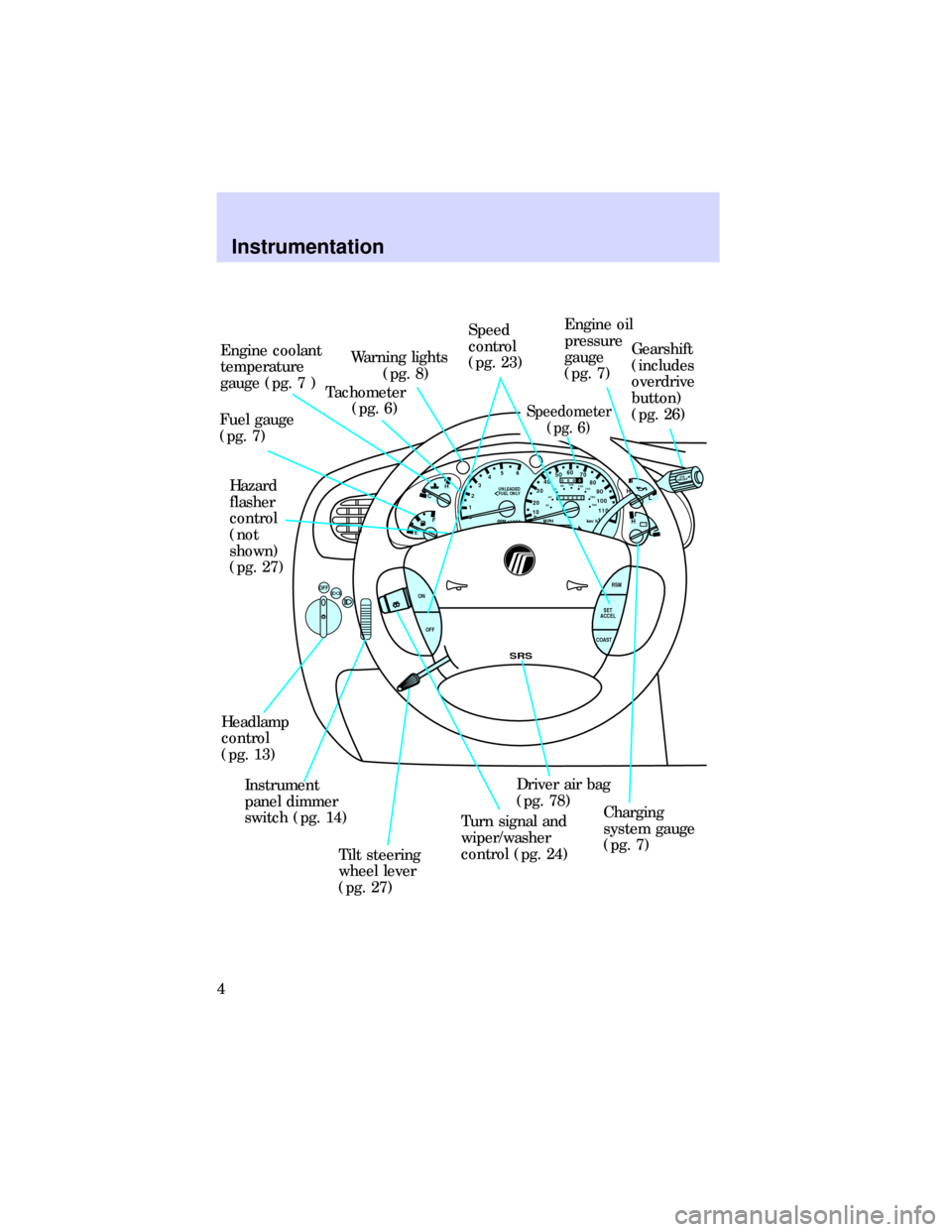
Engine coolant
temperature
gauge (pg. 7 )
Tachometer
(pg. 6) Warning lights
(pg. 8)Speed
control
(pg. 23)
Speedometer
(pg. 6)
Engine oil
pressure
gauge
(pg. 7)Gearshift
(includes
overdrive
button)
(pg. 26)
Charging
system gauge
(pg. 7) Driver air bag
(pg. 78)
Turn signal and
wiper/washer
control (pg. 24)
Tilt steering
wheel lever
(pg. 27) Instrument
panel dimmer
switch (pg. 14) Headlamp
control
(pg. 13)Hazard
flasher
control
(not
shown)
(pg. 27) Fuel gauge
(pg. 7)
Instrumentation
4
Page 14 of 197

Daytime running light (DRL)
system (if equipped)
The daytime running light (DRL)
system turns the high beam lamps
on, with a reduced light output,
when:
²The headlamp knob is in the
OFF position.
²The engine is running.
²The parking brake is released.
The daytime running light
(DRL) system will not
illuminate the tail lamps and
parking lamps. Turn on your
headlamps at dusk. Failure to do
so may result in a collision.
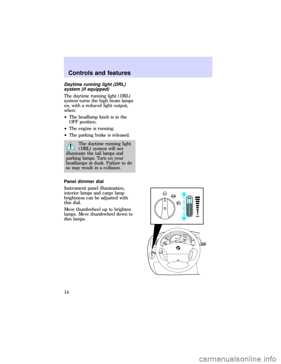
Panel dimmer dial
Instrument panel illumination,
interior lamps and cargo lamp
brightness can be adjusted with
this dial.
Move thumbwheel up to brighten
lamps. Move thumbwheel down to
dim lamps.
0P RND21
UNLEADED
FUEL ONLY
RPM x 100012345
6H
C
F
E
RSM
SET
ACC
COAST OFF ONOFF
SRS
OFF
DIM
020
1030405060
70
80
90
110
120000000oooo
km/h100
20406080100
120
140
160
180
Controls and features
14
Page 22 of 197

STEERING COLUMN
CONTROLS
Positions of the ignition
ACCESSORYallows electrical
accessories such as radio and
wipers/washer to operate while the
engine is not running.
LOCKlocks the steering wheel
and gearshift lever.
OFFshuts off the ignition and
accessories and allows the
gearshift lever and steering wheel
to move.
ONtests the warning lights. The
key remains here when engine is
running.
STARTcranks the engine. The key
returns toONwhen released.
00P RND21
UNLEADED
FUEL ONLY
RPM x 100012345
6H
C
F
E
RSM
SET
ACC
COAST OFF ON
SRS
- +
H
H
L L020
1030405060
70
80
90
110
120000000oooo
km/h100
20406080100
120
140
160
180
ON
START
LOCK
ACCESSORYOFF
Controls and features
22
Page 27 of 197

Hazard flasher
Push the hazard flasher button.
The button will pop out and the
lamps will begin to flash.
To stop the flashers, push the
flasher button again.
Tilt steering
Never adjust the steering
column while the vehicle is
moving.
Pull the tilt steering lever towards
you and move the wheel to the
desired position.
0P RND21
UNLEADED
FUEL ONLY
RPM x 100012345
6H
C
F
E
RSM
SET
ACC
COAST OFF ON
SRS
- +H
H
L L020
1030405060
70
80
90
110
120000000oooo
km/h100
20406080100
120
140
160
180
0P RND21
UNLEADED
FUEL ONLY
RPM x 100012345
6H
C
F
E
RSM
SET
ACC
COAST OFF ON
SRS
- +H
H
L L020
1030405060
70
80
90
110
120000000oooo
km/h100
20406080100
120
140
160
180
Controls and features
27
Page 41 of 197

liftgate will unlock when the key
is returned to the vertical
position (position of key before
removal).
This feature can be activated by all
outside locks on vehicles equipped
with keyless entry.
Illuminated entry
Interior lamps illuminate when
either outside front door handle is
lifted, unlocked with the keyless
entry keypad or the UNLOCK
button is pressed on the remote
entry transmitter (seeRemote
entry systemorKeyless entry
systemfor further information).
The system will automatically turn
off after 25 seconds or when the
ignition switch is turned to START
or ON position.
The inside lights will not turn off if
you have turned them on with the
dimmer thumbwheel or if any door
is open. However, the battery saver
will turn them off after ten
minutes. SeeBattery saverfor
more information.
Controls and features
41
Page 72 of 197

passenger in the event of a
collision.
All occupants of the
vehicle, including the
driver, should always wear their
safety belts, even when an air
bag supplemental restraint
system is provided.
Do not place objects or
mount equipment on or
near the air bag cover on the
steering wheel or in front seat
areas that may come into contact
with a deploying air bag. Failure
to follow this instruction may
increase the risk of personal
injury in the event of a collision.
Do not attempt to service,
repair, or modify the air
bag supplemental restraint
system or its fuses. See your
Ford or Lincoln-Mercury dealer.
Rear-facing child seats or
infant carriers should
never be placed in the front seat.
Air bags and air bag equipped
vehicles should be disposed of only
by your dealer.
Seating and safety restraints
72
Page 73 of 197

AIR BAG DESCRIPTION
The air bag system activates in
collisions more severe than hitting
a parked vehicle of similar size and
weight head-on at about 45km/h
(28 mph).
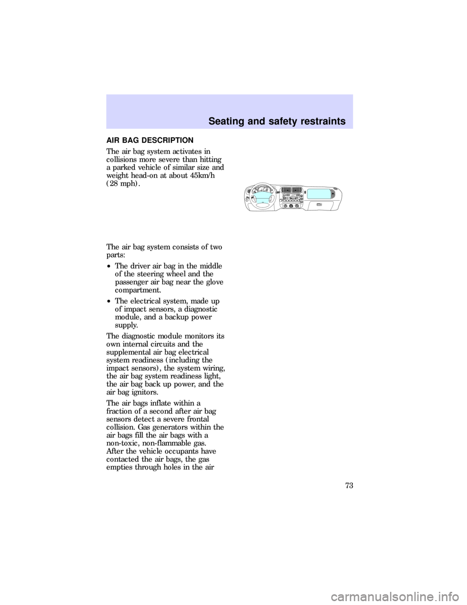
The air bag system consists of two
parts:
²The driver air bag in the middle
of the steering wheel and the
passenger air bag near the glove
compartment.
²The electrical system, made up
of impact sensors, a diagnostic
module, and a backup power
supply.
The diagnostic module monitors its
own internal circuits and the
supplemental air bag electrical
system readiness (including the
impact sensors), the system wiring,
the air bag system readiness light,
the air bag back up power, and the
air bag ignitors.
The air bags inflate within a
fraction of a second after air bag
sensors detect a severe frontal
collision. Gas generators within the
air bags fill the air bags with a
non-toxic, non-flammable gas.
After the vehicle occupants have
contacted the air bags, the gas
empties through holes in the air
EOFF0020406080100
120
140
160
180
200P RND21000000ooookm/hUNLEADED
FUEL ONLY
RPM x 100012345
6H
CEF
RSM
SET
ACC
COAST OFF ONOFFSRSHI LOOFF*A/C*MAX
A/CREW
1FF
2SIDE 1-2
3FM 1STVOL – PUSH ON
AM
FMBASS TREBBAL FADE
AUTO
SET CLKSEEKTUNE
DISCSSCAN4DOLBY SYSTEMEJTAPE CDCOMP
5SHUFFLE
6PUSH
Seating and safety restraints
73
Page 96 of 197

BRAKES
The anti-lock brake system
(ABS)
Anti-lock brake operation differs
slightly from standard brake
operation.
Apply the brakes steadily. DO NOT
pump the brakes in a panic stop.
The brake system will prevent
wheel lockup by automatically
releasing and reapplying the
brakes.
Even with ABS, the brakes could
lock up on roads with alternating
slippery and dry patches or with
loose surfaces such as snow or
gravel. Be careful when braking.
The ABS conducts a self-test each
time the vehicle is driven. A
mechanical noise may be heard
while the system conducts its
self-test.
Occasional brake squeal during
light to moderate stops is normal.
Significantly increased squeal is an
indicator that brake service is
needed.
After driving through standing
water, gently apply the brakes
several times to dry them.
If driving down a long or steep hill,
shift to a lower gear and do not
apply the brakes continuously.
Continuously applying the brakes
on a hill could overheat them and
make them less effective.
Driving
96