ESP MINI 3 door 2014 Owner's Guide
[x] Cancel search | Manufacturer: MINI, Model Year: 2014, Model line: 3 door, Model: MINI 3 door 2014Pages: 240, PDF Size: 11.05 MB
Page 116 of 240
Configure the program.
SPORT can also be configured before it is acti‐
vated:1. "Settings"2."Driving mode"3."Configure SPORT"
This configuration is retrieved when SPORT is
activated.
Configuring driving program
Settings can be made for the following driving
programs in Driving mode:
▷GREEN, refer to page 111.▷SPORT, refer to page 111.
Displays
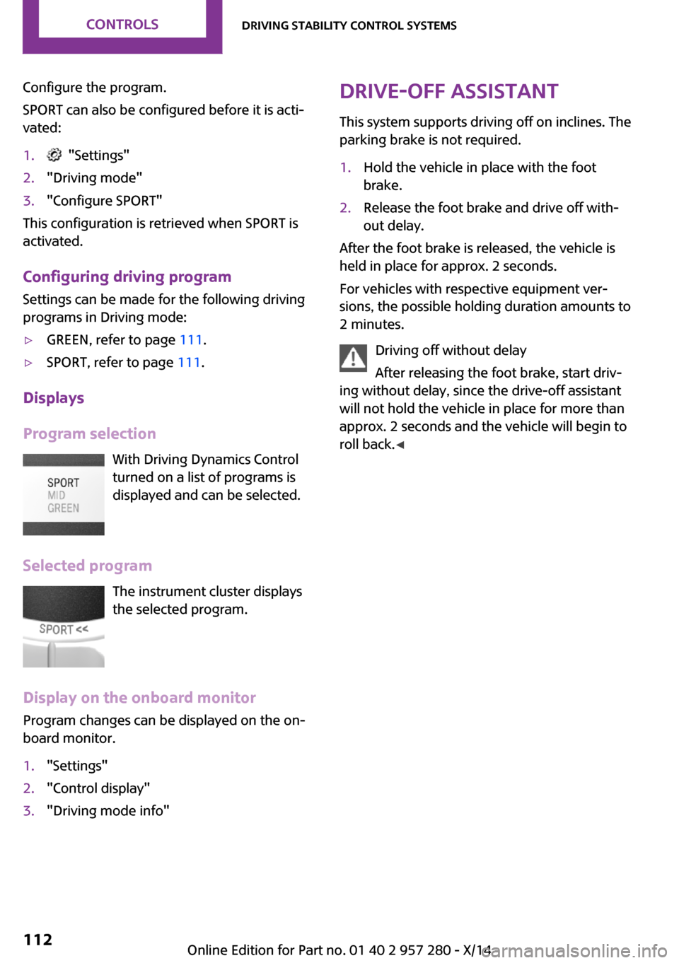
Program selection With Driving Dynamics Control
turned on a list of programs is
displayed and can be selected.
Selected program The instrument cluster displays
the selected program.
Display on the onboard monitor
Program changes can be displayed on the on‐
board monitor.
1."Settings"2."Control display"3."Driving mode info"Drive-off assistant
This system supports driving off on inclines. The
parking brake is not required.1.Hold the vehicle in place with the foot
brake.2.Release the foot brake and drive off with‐
out delay.
After the foot brake is released, the vehicle is
held in place for approx. 2 seconds.
For vehicles with respective equipment ver‐
sions, the possible holding duration amounts to
2 minutes.
Driving off without delay
After releasing the foot brake, start driv‐
ing without delay, since the drive-off assistant
will not hold the vehicle in place for more than
approx. 2 seconds and the vehicle will begin to
roll back. ◀
Seite 112CONTROLSDriving stability control systems112
Online Edition for Part no. 01 40 2 957 280 - X/14
Page 117 of 240
Driving comfortVehicle features and op‐
tions
This chapter describes all standard, country-
specific and optional features offered with the
series. It also describes features that are not
necessarily available in your car, e. g., due to
the selected options or country versions. This
also applies to safety-related functions and sys‐
tems.
Camera-based cruise con‐
trol, ACC
The concept Use this system to select a desired speed that
the vehicle will maintain automatically on clear
roads.
To the extent possible, the system automati‐
cally adjusts the speed to a slower vehicle
ahead of you.
A camera on the interior rear view mirror is
used to detect vehicles driving ahead.
The distance that the vehicle maintains to the
vehicle ahead of you can be varied.
For safety reasons, it depends on the speed.
To maintain a certain distance, the system au‐
tomatically decelerates, applies the brakes
lightly, or accelerates again if the vehicle ahead
begins moving faster.
As soon as the road is clear, the vehicle acceler‐
ates to the desired speed.
The speed is also maintained downhill, but may
not be maintained uphill if engine power is in‐
sufficient.General information
The system is functional at speeds beginning at
approx. 20 mph/30 km/h.
Depending on the set drive mode, refer to
page 111, the features of the cruise control can
change in certain areas.
Hints Personal responsibility
Even an active system holds the driver re‐
sponsible for his or her driving, particularly for
staying in your lane, adjusting your speed,
keeping your distance and for your driving style
all in relation to traffic.
Technically the system has its limits, it cannot
independently react to all traffic situations.
Monitor your driving, be on the alert, observe
the vehicle surroundings and other traffic and
react when needed, e.g. through braking,
steering or make evasive maneuvers - risk of
accident. ◀
Unfavorable weather conditions
In the event of unfavorable weather and
light conditions, for instance if there is rain,
snowfall, slush, fog or glare, this may result in
poorer recognition of traffic situations as well
as short-term interruptions for vehicles that are
already detected. Drive attentively, and react to
the current traffic situation. Intervene actively
when necessary, e.g., by braking, steering or
making an evasive maneuver, otherwise, there
is the risk of an accident. ◀Seite 113Driving comfortCONTROLS113
Online Edition for Part no. 01 40 2 957 280 - X/14
Page 119 of 240
▷The detection range of the camera is dis‐
torted, e.g., by soiling, heavy precipitation
or glare effects from the sun.▷The vehicle in front decelerates below a
speed of approx. 20 mph/30 km/h.
Maintaining, storing, and changing the
speed
Hints Adjusting the desired speed
Modify desired speed to road conditions
and be ready to brake at all times; otherwise,
there is the risk of an accident. ◀
Differences in speed
Large differences in speed relative to
other vehicles cannot be compensated by the
system such as in the following situations:
▷When fast approaching a slowly moving ve‐
hicle.▷When another vehicle suddenly swerves
into the wrong lane. ◀
Maintaining/storing the speed
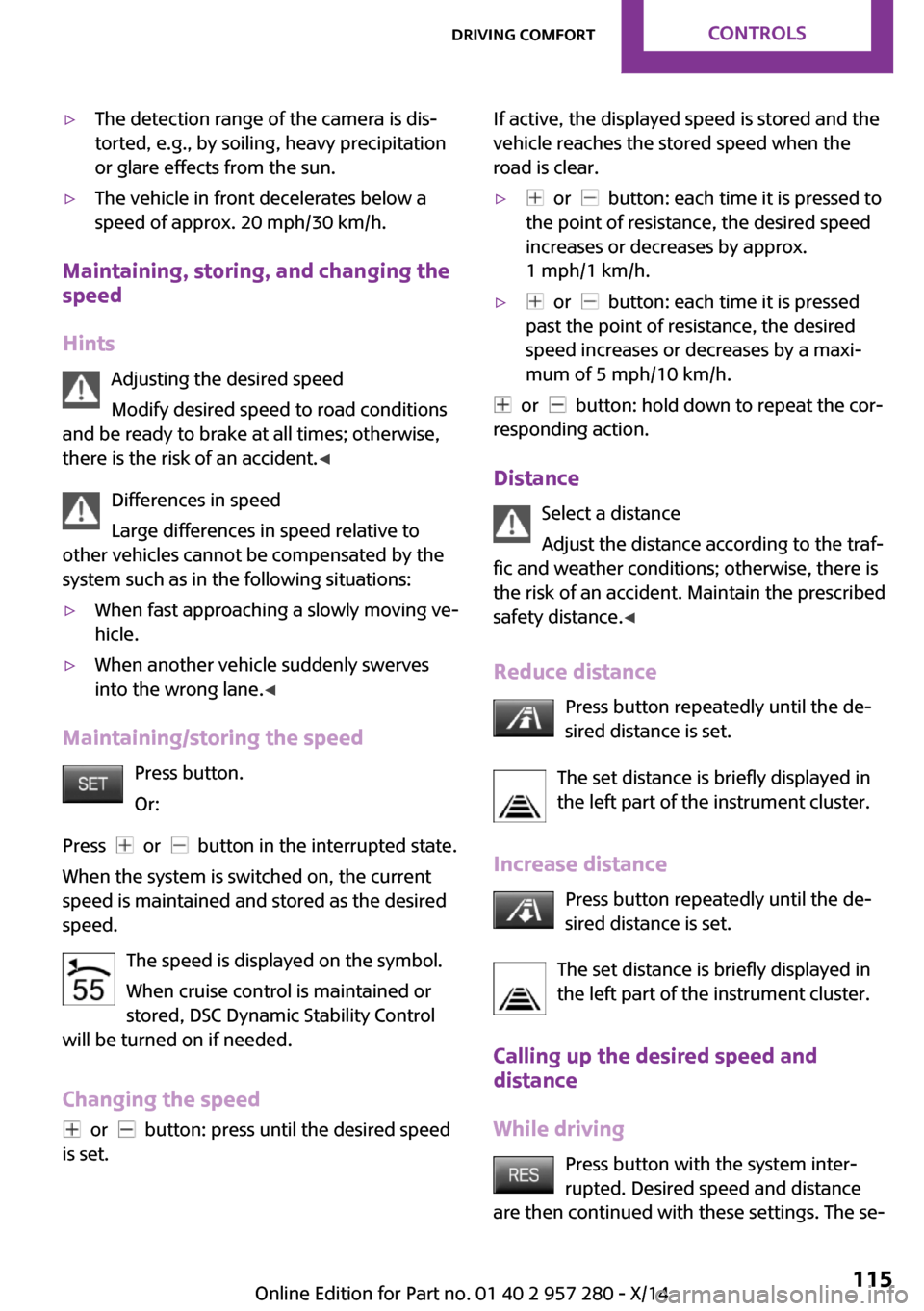
Press button.
Or:
Press
or button in the interrupted state.
When the system is switched on, the current
speed is maintained and stored as the desired
speed.
The speed is displayed on the symbol.
When cruise control is maintained or
stored, DSC Dynamic Stability Control
will be turned on if needed.
Changing the speed
or button: press until the desired speed
is set.
If active, the displayed speed is stored and the
vehicle reaches the stored speed when the
road is clear.▷ or button: each time it is pressed to
the point of resistance, the desired speed
increases or decreases by approx.
1 mph/1 km/h.▷ or button: each time it is pressed
past the point of resistance, the desired
speed increases or decreases by a maxi‐
mum of 5 mph/10 km/h.
or button: hold down to repeat the cor‐
responding action.
Distance Select a distance
Adjust the distance according to the traf‐
fic and weather conditions; otherwise, there is
the risk of an accident. Maintain the prescribed
safety distance. ◀
Reduce distance Press button repeatedly until the de‐
sired distance is set.
The set distance is briefly displayed in
the left part of the instrument cluster.
Increase distance Press button repeatedly until the de‐
sired distance is set.
The set distance is briefly displayed in
the left part of the instrument cluster.
Calling up the desired speed and
distance
While driving Press button with the system inter‐
rupted. Desired speed and distance
are then continued with these settings. The se‐
Seite 115Driving comfortCONTROLS115
Online Edition for Part no. 01 40 2 957 280 - X/14
Page 120 of 240
lected distance is briefly displayed in the info
display.
In the following cases, the stored speed value is
deleted and cannot be called up again:▷When the system is switched off.▷When the ignition is switched off.
Changing between cruise control with/
without distance control
Traffic ahead
The cruise control does not react to traffic
driving ahead of you, but instead maintains the
stored speed. Take this factor into account – you yourself must react; otherwise, there is the
risk of an accident. ◀
To reel over to cruise control: Press and hold this button, or
Press and hold this button.
The indicator lamp in the instrument
cluster comes on and check-control
message is displayed as soon as the reel
is made to cruise control.
To reel back to the camera-based cruise con‐
trol, press one of the buttons.
Displays in the instrument cluster
Desired speed In addition to the indicator lamp, the
desired speed is displayed in the info
display.
▷The indicator lights up green: the system is
active.▷The indicator lights up orange: the system
has been interrupted.▷No display: system is switched off.Brief status display
Selected desired speed.
If --- appears briefly on the display for Check
Control messages, it is possible that the system
requirements are currently not ready for opera‐
tions.
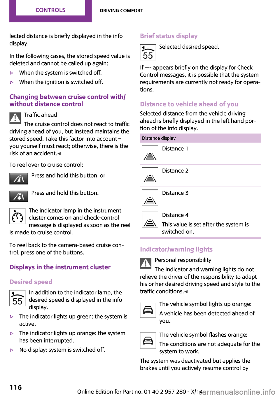
Distance to vehicle ahead of you Selected distance from the vehicle driving
ahead is briefly displayed in the left hand por‐
tion of the info display.Distance displayDistance 1Distance 2Distance 3Distance 4
This value is set after the system is
switched on.
Indicator/warning lights
Personal responsibility
The indicator and warning lights do not
relieve the driver of the responsibility to adapt
his or her desired driving speed and style to the
traffic conditions. ◀
The vehicle symbol lights up orange:
A vehicle has been detected ahead of
you.
The vehicle symbol flashes orange:
The conditions are not adequate for the
system to work.
The system was deactivated but applies the
brakes until you actively resume control by
Seite 116CONTROLSDriving comfort116
Online Edition for Part no. 01 40 2 957 280 - X/14
Page 129 of 240
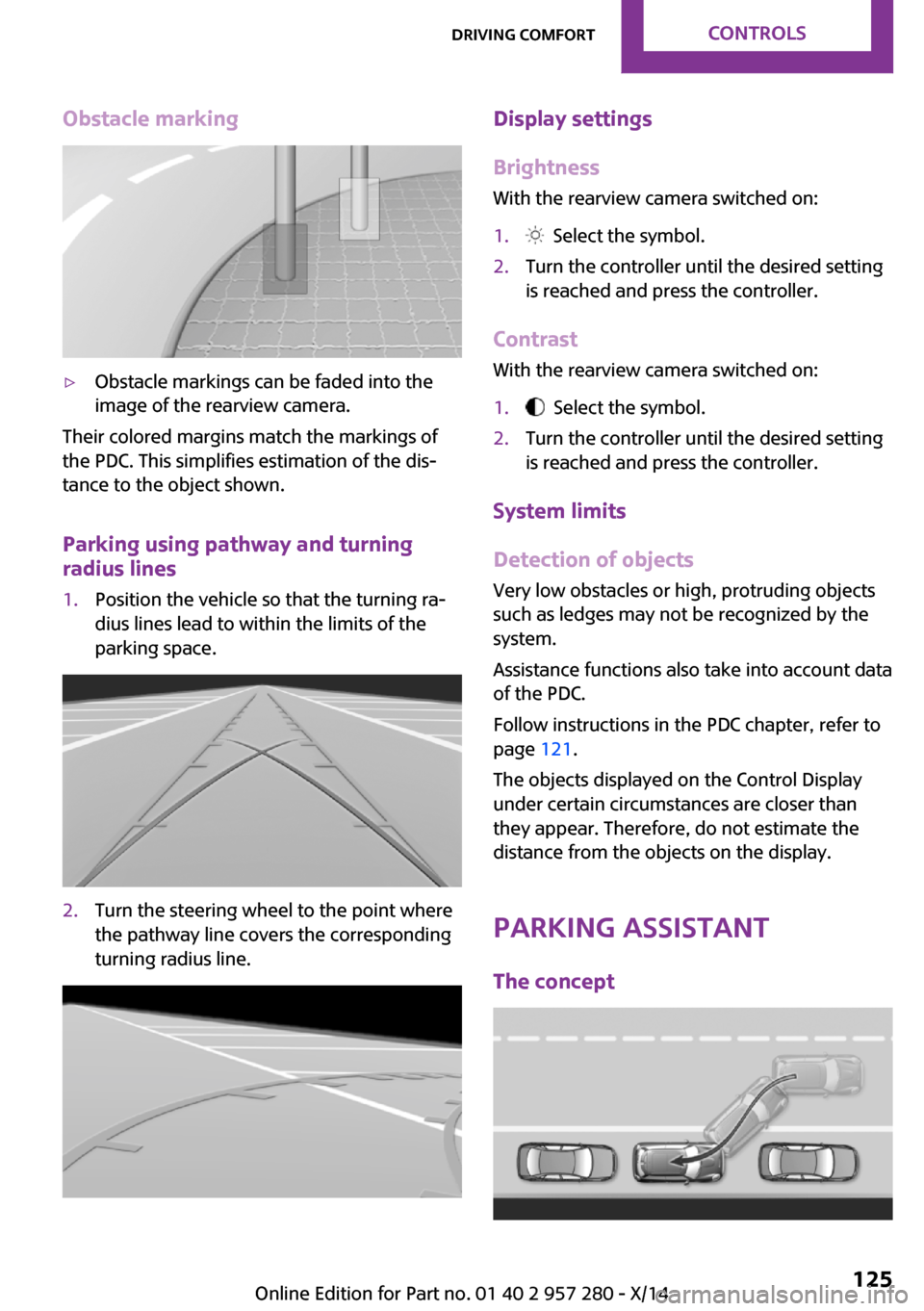
Obstacle marking▷Obstacle markings can be faded into the
image of the rearview camera.
Their colored margins match the markings of
the PDC. This simplifies estimation of the dis‐
tance to the object shown.
Parking using pathway and turning
radius lines
1.Position the vehicle so that the turning ra‐
dius lines lead to within the limits of the
parking space.2.Turn the steering wheel to the point where
the pathway line covers the corresponding
turning radius line.Display settings
Brightness
With the rearview camera switched on:1. Select the symbol.2.Turn the controller until the desired setting
is reached and press the controller.
Contrast
With the rearview camera switched on:
1. Select the symbol.2.Turn the controller until the desired setting
is reached and press the controller.
System limits
Detection of objects
Very low obstacles or high, protruding objects
such as ledges may not be recognized by the
system.
Assistance functions also take into account data
of the PDC.
Follow instructions in the PDC chapter, refer to
page 121.
The objects displayed on the Control Display
under certain circumstances are closer than
they appear. Therefore, do not estimate the
distance from the objects on the display.
Parking assistant
The concept
Seite 125Driving comfortCONTROLS125
Online Edition for Part no. 01 40 2 957 280 - X/14
Page 130 of 240
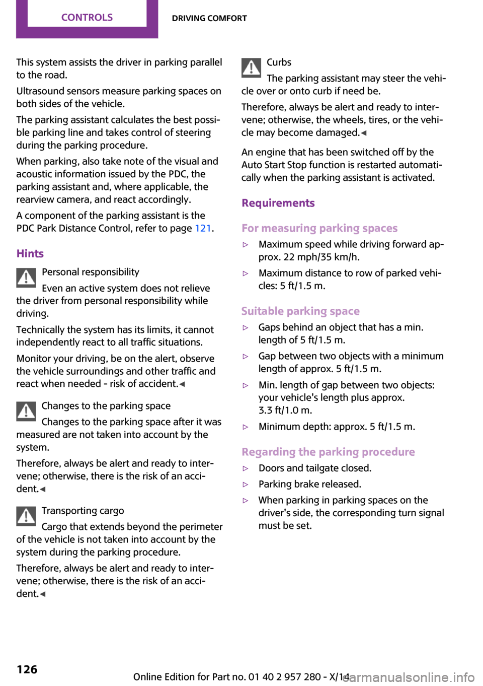
This system assists the driver in parking parallel
to the road.
Ultrasound sensors measure parking spaces on
both sides of the vehicle.
The parking assistant calculates the best possi‐
ble parking line and takes control of steering
during the parking procedure.
When parking, also take note of the visual and
acoustic information issued by the PDC, the
parking assistant and, where applicable, the
rearview camera, and react accordingly.
A component of the parking assistant is the
PDC Park Distance Control, refer to page 121.
Hints Personal responsibility
Even an active system does not relieve
the driver from personal responsibility while
driving.
Technically the system has its limits, it cannot
independently react to all traffic situations.
Monitor your driving, be on the alert, observe
the vehicle surroundings and other traffic and
react when needed - risk of accident. ◀
Changes to the parking space
Changes to the parking space after it was
measured are not taken into account by the system.
Therefore, always be alert and ready to inter‐
vene; otherwise, there is the risk of an acci‐
dent. ◀
Transporting cargo
Cargo that extends beyond the perimeter
of the vehicle is not taken into account by the
system during the parking procedure.
Therefore, always be alert and ready to inter‐ vene; otherwise, there is the risk of an acci‐
dent. ◀Curbs
The parking assistant may steer the vehi‐
cle over or onto curb if need be.
Therefore, always be alert and ready to inter‐
vene; otherwise, the wheels, tires, or the vehi‐
cle may become damaged. ◀
An engine that has been switched off by the
Auto Start Stop function is restarted automati‐
cally when the parking assistant is activated.
Requirements
For measuring parking spaces▷Maximum speed while driving forward ap‐
prox. 22 mph/35 km/h.▷Maximum distance to row of parked vehi‐
cles: 5 ft/1.5 m.
Suitable parking space
▷Gaps behind an object that has a min.
length of 5 ft/1.5 m.▷Gap between two objects with a minimum
length of approx. 5 ft/1.5 m.▷Min. length of gap between two objects:
your vehicle's length plus approx.
3.3 ft/1.0 m.▷Minimum depth: approx. 5 ft/1.5 m.
Regarding the parking procedure
▷Doors and tailgate closed.▷Parking brake released.▷When parking in parking spaces on the
driver's side, the corresponding turn signal
must be set.Seite 126CONTROLSDriving comfort126
Online Edition for Part no. 01 40 2 957 280 - X/14
Page 135 of 240
Climate control functions in detail
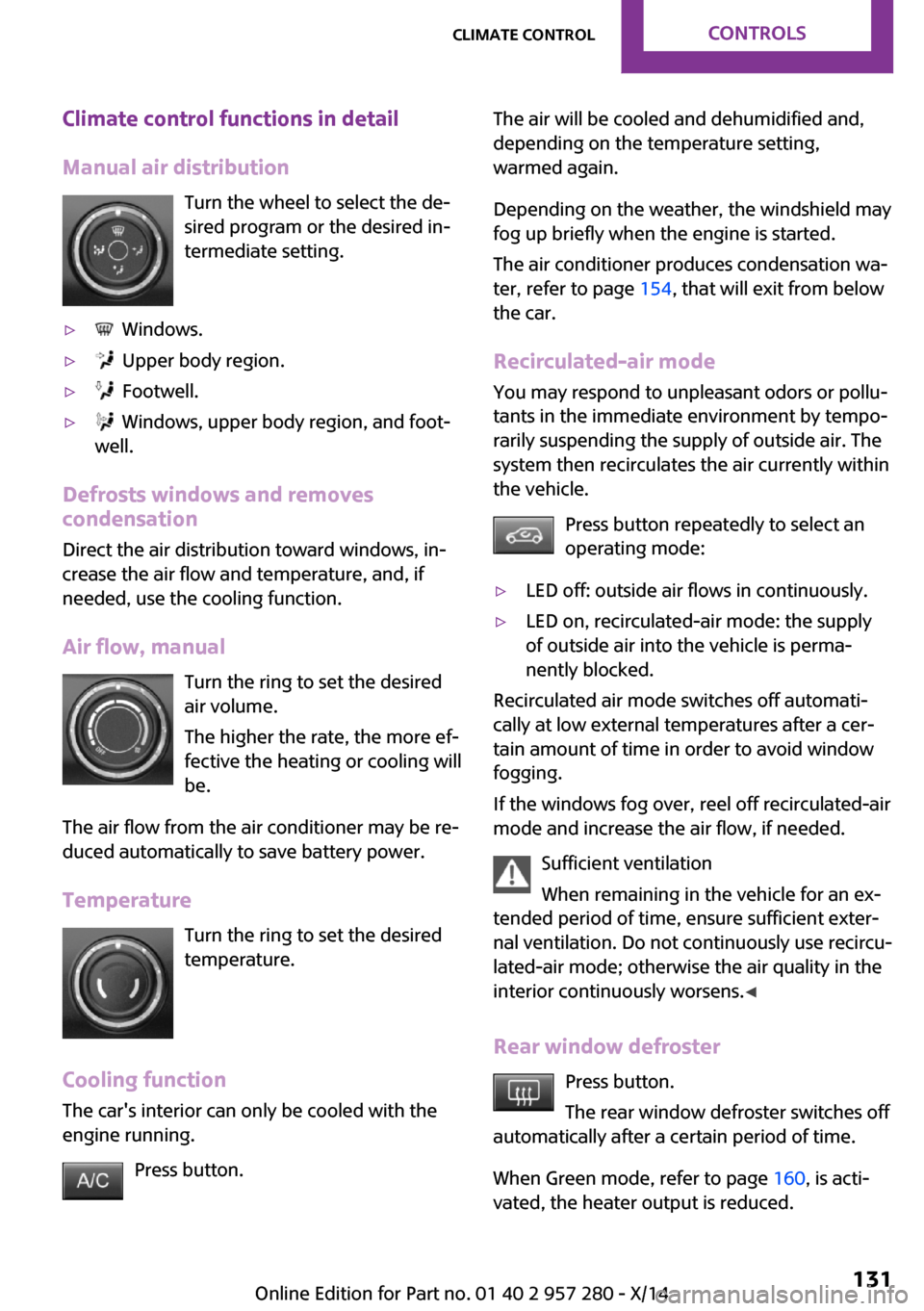
Manual air distribution Turn the wheel to select the de‐
sired program or the desired in‐
termediate setting.▷ Windows.▷ Upper body region.▷ Footwell.▷ Windows, upper body region, and foot‐
well.
Defrosts windows and removes
condensation
Direct the air distribution toward windows, in‐
crease the air flow and temperature, and, if
needed, use the cooling function.
Air flow, manual Turn the ring to set the desired
air volume.
The higher the rate, the more ef‐
fective the heating or cooling will
be.
The air flow from the air conditioner may be re‐
duced automatically to save battery power.
Temperature Turn the ring to set the desired
temperature.
Cooling function The car's interior can only be cooled with the
engine running.
Press button.
The air will be cooled and dehumidified and,
depending on the temperature setting,
warmed again.
Depending on the weather, the windshield may
fog up briefly when the engine is started.
The air conditioner produces condensation wa‐
ter, refer to page 154, that will exit from below
the car.
Recirculated-air mode You may respond to unpleasant odors or pollu‐
tants in the immediate environment by tempo‐
rarily suspending the supply of outside air. The
system then recirculates the air currently within
the vehicle.
Press button repeatedly to select an
operating mode:▷LED off: outside air flows in continuously.▷LED on, recirculated-air mode: the supply
of outside air into the vehicle is perma‐
nently blocked.
Recirculated air mode switches off automati‐
cally at low external temperatures after a cer‐
tain amount of time in order to avoid window
fogging.
If the windows fog over, reel off recirculated-air
mode and increase the air flow, if needed.
Sufficient ventilation
When remaining in the vehicle for an ex‐
tended period of time, ensure sufficient exter‐
nal ventilation. Do not continuously use recircu‐
lated-air mode; otherwise the air quality in the
interior continuously worsens. ◀
Rear window defroster Press button.
The rear window defroster switches off
automatically after a certain period of time.
When Green mode, refer to page 160, is acti‐
vated, the heater output is reduced.
Seite 131Climate controlCONTROLS131
Online Edition for Part no. 01 40 2 957 280 - X/14
Page 138 of 240
▷Windows.
Maximum coolingPress button.
The system is set to the lowest temper‐
ature, maximum air flow and recirculated-air
mode.
Air flows out of the vents to the upper body re‐
gion. The vents need to be open for this.
The function is available with external tempera‐
tures beyond approx. 32 ℉/0 ℃ and with the
engine running.
Adjust air flow with the program active.
Cooling function The car's interior can only be cooled with the
engine running.
Press button.
The air will be cooled and dehumidi‐
fied and, depending on the temperature set‐
ting, warmed again.
Depending on the weather, the windshield may
fog up briefly when the engine is started.
The cooling function is switched on automati‐
cally with the AUTO program.
When using the automatic climate control, con‐
densation water, refer to page 154, develops
that exits underneath the vehicle.
Automatic recirculated-air control/
recirculated-air mode
You may respond to unpleasant odors or pollu‐
tants in the immediate environment by tempo‐
rarily suspending the supply of outside air. The
system then recirculates the air currently within
the vehicle.
Press button repeatedly to select an
operating mode:
▷LEDs off: outside air flows in continuously.▷Left LED on, automatic recirculated-air con‐
trol: a sensor detects pollutants in the out‐
side air and shuts off automatically.▷Right LED on, recirculated-air mode: the
supply of outside air into the vehicle is per‐
manently blocked.
Recirculated air mode switches off automati‐
cally at low external temperatures after a cer‐
tain amount of time in order to avoid window
fogging.
If windows are fogged over, reel off the recircu‐
lating mode and press the AUTO button. Make
sure that air can flow to the windshield.
Sufficient ventilation
When remaining in the vehicle for an ex‐
tended period of time, ensure sufficient exter‐
nal ventilation. Do not continuously use recircu‐
lated-air mode; otherwise the air quality in the
interior continuously worsens. ◀
Rear window defroster Press button.
The rear window defroster switches off
automatically after a certain period of time.
When Green mode, refer to page 160, is acti‐
vated, the heater output is reduced.
Windshield defroster Press button.
The front window defroster switches
off automatically after a certain period of time.
Defrosts windows and removes
condensation
Press button.
Ice and condensation are quickly re‐
moved from the windshield and the front side
windows.
Adjust air flow with the program active.
Seite 134CONTROLSClimate control134
Online Edition for Part no. 01 40 2 957 280 - X/14
Page 144 of 240
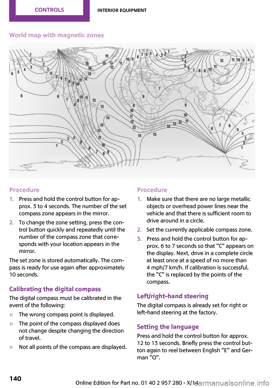
World map with magnetic zonesProcedure1.Press and hold the control button for ap‐
prox. 3 to 4 seconds. The number of the set
compass zone appears in the mirror.2.To change the zone setting, press the con‐
trol button quickly and repeatedly until the
number of the compass zone that corre‐
sponds with your location appears in the
mirror.
The set zone is stored automatically. The com‐
pass is ready for use again after approximately
10 seconds.
Calibrating the digital compass The digital compass must be calibrated in the
event of the following:
▷The wrong compass point is displayed.▷The point of the compass displayed does
not change despite changing the direction
of travel.▷Not all points of the compass are displayed.Procedure1.Make sure that there are no large metallic
objects or overhead power lines near the
vehicle and that there is sufficient room to
drive around in a circle.2.Set the currently applicable compass zone.3.Press and hold the control button for ap‐
prox. 6 to 7 seconds so that "C" appears on
the display. Next, drive in a complete circle
at least once at a speed of no more than
4 mph/7 km/h. If calibration is successful,
the "C" is replaced by the points of the
compass.
Left/right-hand steering
The digital compass is already set for right or
left-hand steering at the factory.
Setting the language
Press and hold the control button for approx.
12 to 13 seconds. Briefly press the control but‐ ton again to reel between English "E" and Ger‐
man "O".
Seite 140CONTROLSInterior equipment140
Online Edition for Part no. 01 40 2 957 280 - X/14
Page 147 of 240
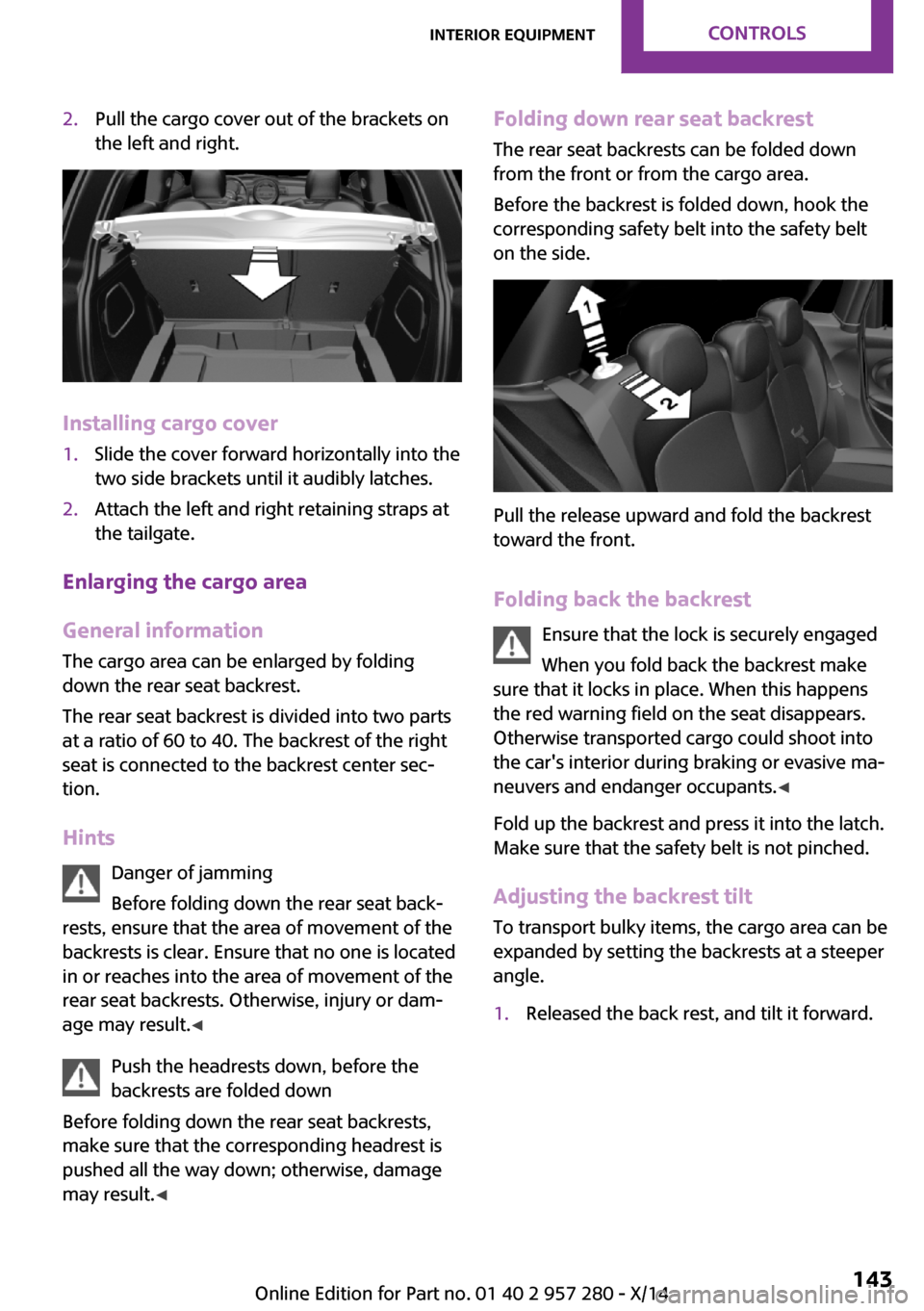
2.Pull the cargo cover out of the brackets on
the left and right.
Installing cargo cover
1.Slide the cover forward horizontally into the
two side brackets until it audibly latches.2.Attach the left and right retaining straps at
the tailgate.
Enlarging the cargo area
General information
The cargo area can be enlarged by folding
down the rear seat backrest.
The rear seat backrest is divided into two parts
at a ratio of 60 to 40. The backrest of the right
seat is connected to the backrest center sec‐
tion.
Hints Danger of jamming
Before folding down the rear seat back‐
rests, ensure that the area of movement of the
backrests is clear. Ensure that no one is located
in or reaches into the area of movement of the
rear seat backrests. Otherwise, injury or dam‐
age may result. ◀
Push the headrests down, before the
backrests are folded down
Before folding down the rear seat backrests,
make sure that the corresponding headrest is
pushed all the way down; otherwise, damage
may result. ◀
Folding down rear seat backrest
The rear seat backrests can be folded down
from the front or from the cargo area.
Before the backrest is folded down, hook the
corresponding safety belt into the safety belt
on the side.
Pull the release upward and fold the backrest
toward the front.
Folding back the backrest Ensure that the lock is securely engaged
When you fold back the backrest make
sure that it locks in place. When this happens
the red warning field on the seat disappears.
Otherwise transported cargo could shoot into
the car's interior during braking or evasive ma‐
neuvers and endanger occupants. ◀
Fold up the backrest and press it into the latch.
Make sure that the safety belt is not pinched.
Adjusting the backrest tilt To transport bulky items, the cargo area can be
expanded by setting the backrests at a steeper
angle.
1.Released the back rest, and tilt it forward.Seite 143Interior equipmentCONTROLS143
Online Edition for Part no. 01 40 2 957 280 - X/14