ESP MINI 3 door 2014 Workshop Manual
[x] Cancel search | Manufacturer: MINI, Model Year: 2014, Model line: 3 door, Model: MINI 3 door 2014Pages: 240, PDF Size: 11.05 MB
Page 200 of 240
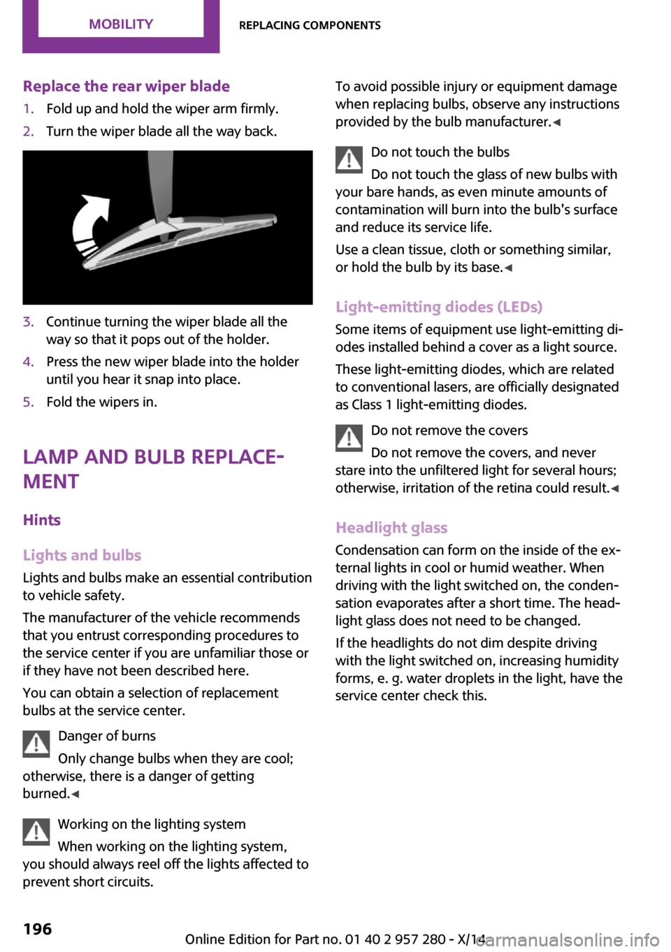
Replace the rear wiper blade1.Fold up and hold the wiper arm firmly.2.Turn the wiper blade all the way back.3.Continue turning the wiper blade all the
way so that it pops out of the holder.4.Press the new wiper blade into the holder
until you hear it snap into place.5.Fold the wipers in.
Lamp and bulb replace‐
ment
Hints
Lights and bulbs Lights and bulbs make an essential contribution
to vehicle safety.
The manufacturer of the vehicle recommends
that you entrust corresponding procedures to
the service center if you are unfamiliar those or
if they have not been described here.
You can obtain a selection of replacement
bulbs at the service center.
Danger of burns
Only change bulbs when they are cool;
otherwise, there is a danger of getting
burned. ◀
Working on the lighting system
When working on the lighting system,
you should always reel off the lights affected to
prevent short circuits.
To avoid possible injury or equipment damage
when replacing bulbs, observe any instructions
provided by the bulb manufacturer. ◀
Do not touch the bulbs
Do not touch the glass of new bulbs with
your bare hands, as even minute amounts of
contamination will burn into the bulb's surface
and reduce its service life.
Use a clean tissue, cloth or something similar,
or hold the bulb by its base. ◀
Light-emitting diodes (LEDs)
Some items of equipment use light-emitting di‐
odes installed behind a cover as a light source.
These light-emitting diodes, which are related
to conventional lasers, are officially designated as Class 1 light-emitting diodes.
Do not remove the covers
Do not remove the covers, and never
stare into the unfiltered light for several hours;
otherwise, irritation of the retina could result. ◀
Headlight glass Condensation can form on the inside of the ex‐
ternal lights in cool or humid weather. When
driving with the light switched on, the conden‐
sation evaporates after a short time. The head‐ light glass does not need to be changed.
If the headlights do not dim despite driving
with the light switched on, increasing humidity
forms, e. g. water droplets in the light, have the
service center check this.Seite 196MOBILITYReplacing components196
Online Edition for Part no. 01 40 2 957 280 - X/14
Page 203 of 240
LED parking lights/LED fog lightsFollow the general instructions on lights and
bulbs, refer to page 196.
The lights feature LED technology. Contact your
service center in the event of a malfunction.
Parking lights/fog lights/daytime
running lights
Follow the general instructions on lights and
bulbs, refer to page 196.
Bulbs:▷Parking lights for halogen headlights: W5W
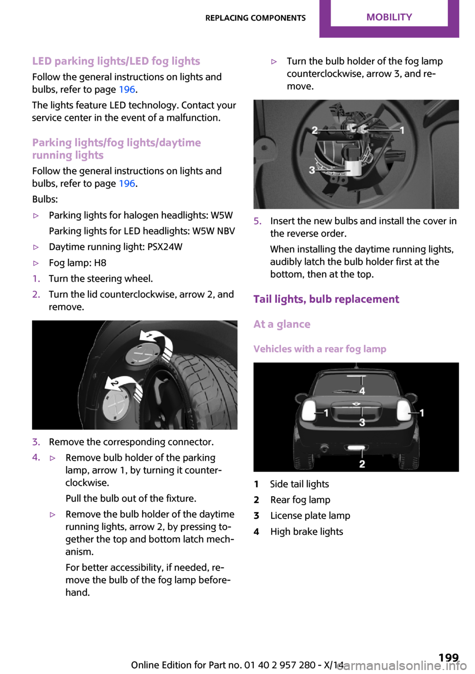
Parking lights for LED headlights: W5W NBV▷Daytime running light: PSX24W▷Fog lamp: H81.Turn the steering wheel.2.Turn the lid counterclockwise, arrow 2, and
remove.3.Remove the corresponding connector.4.▷Remove bulb holder of the parking
lamp, arrow 1, by turning it counter‐
clockwise.
Pull the bulb out of the fixture.▷Remove the bulb holder of the daytime
running lights, arrow 2, by pressing to‐
gether the top and bottom latch mech‐
anism.
For better accessibility, if needed, re‐
move the bulb of the fog lamp before‐
hand.▷Turn the bulb holder of the fog lamp
counterclockwise, arrow 3, and re‐
move.5.Insert the new bulbs and install the cover in
the reverse order.
When installing the daytime running lights,
audibly latch the bulb holder first at the
bottom, then at the top.
Tail lights, bulb replacement
At a glance
Vehicles with a rear fog lamp
1Side tail lights2Rear fog lamp3License plate lamp4High brake lightsSeite 199Replacing componentsMOBILITY199
Online Edition for Part no. 01 40 2 957 280 - X/14
Page 212 of 240
Preparation1.Check whether the battery of the other ve‐
hicle has a voltage of 12 volts. This informa‐
tion can be found on the battery.2.Switch off the engine of the assisting vehi‐
cle.3.Switch off any electronic systems/power
consumers in both vehicles.
Bodywork contact between vehicles
Make sure that there is no contact be‐
tween the bodywork of the two vehicles; other‐
wise, there is a danger of short circuits. ◀
Starting aid terminals Connecting order
Connect the jumper cables in the correct
order to prevent risk of injury from arcing. ◀
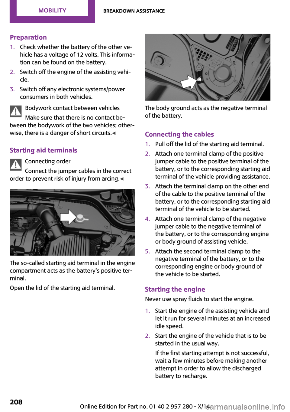
The so-called starting aid terminal in the engine
compartment acts as the battery's positive ter‐
minal.
Open the lid of the starting aid terminal.
The body ground acts as the negative terminal
of the battery.
Connecting the cables
1.Pull off the lid of the starting aid terminal.2.Attach one terminal clamp of the positive
jumper cable to the positive terminal of the
battery, or to the corresponding starting aid
terminal of the vehicle providing assistance.3.Attach the terminal clamp on the other end
of the cable to the positive terminal of the
battery, or to the corresponding starting aid
terminal of the vehicle to be started.4.Attach one terminal clamp of the negative
jumper cable to the negative terminal of
the battery, or to the corresponding engine
or body ground of assisting vehicle.5.Attach the second terminal clamp to the
negative terminal of the battery, or to the
corresponding engine or body ground of
the vehicle to be started.
Starting the engine
Never use spray fluids to start the engine.
1.Start the engine of the assisting vehicle and
let it run for several minutes at an increased
idle speed.2.Start the engine of the vehicle that is to be
started in the usual way.
If the first starting attempt is not successful,
wait a few minutes before making another
attempt in order to allow the discharged
battery to recharge.Seite 208MOBILITYBreakdown assistance208
Online Edition for Part no. 01 40 2 957 280 - X/14
Page 215 of 240
cargo floor panel, next to the onboard vehicle
tool kit, refer to page 195.
Tow fitting, information on use▷Use only the tow fitting provided with
the vehicle and screw it all the way in.▷Use the tow fitting for towing on paved
roads only.▷Avoid lateral loading of the tow fitting, e.g.,
do not lift the vehicle by the tow fitting.
Otherwise, damage to the tow fitting and the
vehicle can occur. ◀
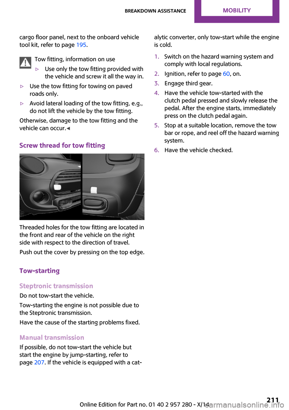
Screw thread for tow fitting
Threaded holes for the tow fitting are located in
the front and rear of the vehicle on the right
side with respect to the direction of travel.
Push out the cover by pressing on the top edge.
Tow-starting
Steptronic transmission Do not tow-start the vehicle.
Tow-starting the engine is not possible due to
the Steptronic transmission.
Have the cause of the starting problems fixed.
Manual transmission
If possible, do not tow-start the vehicle but
start the engine by jump-starting, refer to
page 207. If the vehicle is equipped with a cat‐
alytic converter, only tow-start while the engine
is cold.1.Switch on the hazard warning system and
comply with local regulations.2.Ignition, refer to page 60, on.3.Engage third gear.4.Have the vehicle tow-started with the
clutch pedal pressed and slowly release the
pedal. After the engine starts, immediately
press on the clutch pedal again.5.Stop at a suitable location, remove the tow
bar or rope, and reel off the hazard warning
system.6.Have the vehicle checked.Seite 211Breakdown assistanceMOBILITY211
Online Edition for Part no. 01 40 2 957 280 - X/14
Page 232 of 240
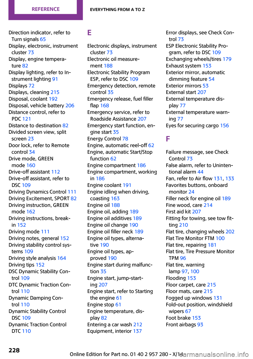
Direction indicator, refer toTurn signals 65
Display, electronic, instrument cluster 73
Display, engine tempera‐ ture 82
Display lighting, refer to In‐ strument lighting 91
Displays 72
Displays, cleaning 215
Disposal, coolant 192
Disposal, vehicle battery 206
Distance control, refer to PDC 121
Distance to destination 82
Divided screen view, split screen 23
Door lock, refer to Remote control 34
Drive mode, GREEN mode 160
Drive-off assistant 112
Drive-off assistant, refer to DSC 109
Driving Dynamics Control 111
Driving Excitement, SPORT 82
Driving instruction, GREEN mode 162
Driving instructions, break- in 152
Driving mode 111
Driving notes, general 152
Driving stability control sys‐ tems 109
Driving style analysis 164
Driving tips 152
DSC Dynamic Stability Con‐ trol 109
DTC Dynamic Traction Con‐ trol 110
Dynamic Damping Con‐ trol 110
Dynamic Stability Control DSC 109
Dynamic Traction Control DTC 110 E
Electronic displays, instrument cluster 73
Electronic oil measure‐ ment 188
Electronic Stability Program ESP, refer to DSC 109
Emergency detection, remote control 35
Emergency release, fuel filler flap 168
Emergency service, refer to Roadside Assistance 207
Emergency start function, en‐ gine start 35
Energy Control 78
Engine, automatic reel-off 62
Engine, automatic Start/Stop function 62
Engine compartment 186
Engine compartment, working in 186
Engine coolant 191
Engine idling when driving, coasting 163
Engine oil 188
Engine oil, adding 189
Engine oil additives 189
Engine oil change 190
Engine oil filler neck 189
Engine oil types, alterna‐ tive 190
Engine oil types, ap‐ proved 190
Engine start during malfunc‐ tion 35
Engine start, jump-start‐ ing 207
Engine start, refer to Starting the engine 61
Engine stop 61
Engine temperature, dis‐ play 82
Entering a car wash 212
Equipment, interior 137 Error displays, see Check Con‐
trol 73
ESP Electronic Stability Pro‐ gram, refer to DSC 109
Exchanging wheels/tires 179
Exhaust system 153
Exterior mirror, automatic dimming feature 54
Exterior mirrors 53
External start 207
External temperature dis‐ play 77
External temperature warn‐ ing 77
Eyes for securing cargo 156
F Failure message, see Check Control 73
False alarm, refer to Uninten‐ tional alarm 44
Fan, refer to Air flow 131, 133
Favorites buttons, onboard monitor 24
Filler neck for engine oil 189
Fine wood, care 214
First aid kit 207
Fitting for towing, see tow fit‐ ting 210
Flat tire, changing wheels 202
Flat Tire Monitor FTM 100
Flat tire, repairing 181
Flat tire, Tire Pressure Monitor TPM 96
Flat tire, warning lamp 97, 100
Flooding 153
Floor carpet, care 215
Floor mats, care 215
Fogged up windows 131
Fold-out position, windshield wipers 67
Foot brake 153
Front airbags 93 Seite 228REFERENCEEverything from A to Z228
Online Edition for Part no. 01 40 2 957 280 - X/14