controls MINI COOPER 2005 Service Manual
[x] Cancel search | Manufacturer: MINI, Model Year: 2005, Model line: COOPER, Model: MINI COOPER 2005Pages: 165, PDF Size: 4.64 MB
Page 79 of 165
77
OVERVIEW REPAIRS OPERATIONCONTROLS DATA INDEX
AIR CONDITIONING SYSTEM
*
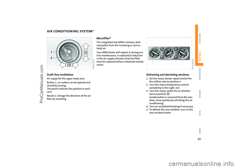
Draft-free ventilation Air supply for the upper body area:Button
1: air outlets can be opened and
closed by turning.
The points indicate the position in each
case.Nozzle
2: change the direction of the air
-
flow by swiveling.
Microfilter* The integrated microfilter removes dust
and pollen from the incoming or recircu
-
lated air.Your MINI Dealer will replace it during rou
-
tine maintenance. A substantial reduction
in the air supply indicates that the filter
must be replaced before scheduled mainte
-
nance.
Defrosting and demisting windows1. Set the rotary blower speed control for
the airflow rate to position
4
2. Turn the rotary temperature control
completely to the right, red3. Turn the rotary switch for air distribu
-
tion to position
.
Condensation is removed from the win
-
dows more quickly by activating the air
conditioning
4. Turn on windshield heating if necessary5. To defrost the rear window: turn on the
rear window heater.
ProCarManuals.com
Page 81 of 165

79
OVERVIEW REPAIRS OPERATIONCONTROLS DATA INDEX
AUTOMATIC CLIMATE CONTROL
*
Automatic air distribution and volume
Automatic program (AUTO):
Indicator lamp lights up.
Automatic adjustment of the air distribu
-
tion and volume, and adaptation of the
specified temperatures to external influ
-
ences, i.e. outside temperature and sun
-
light.In the automatic program (AUTO), the air
conditioning is activated automatically. To
create a pleasant air climate, the air tem
-
perature coming from the vents in the
upper body area is lower than the air tem
-
perature in the footwell.Air volume/Blower
Switching automatic climate control
off/on
Air volume/Blower.
Press the left or right half of the
button. The air volume varies. Automatic
adjustment of the air volume is deacti
-
vated.Switching air conditioner on/off.
Press the left half of the button while the
blower is at the lowest setting. The blower,
heating and air conditioning are switched
off. All displays go out.
Switch the automatic climate control back
on by pressing any button.Air conditioning
Indicator lamp lights up.
The air is cooled and dehumidified
and, depending on the temperature set
-
ting, rewarmed.In the automatic program (AUTO), the air
conditioning is activated automatically. After the engine has started, the wind
-
shield can temporarily fog over. In the air
conditioning mode, there is less condensa
-
tion on the windows.
When the air conditioning is on, con
-
densation is formed which then exits
under the vehicle. Traces of condensed
water on the ground are therefore nor
-
mal.
-
cle is blocked. indicator lamp lights
up.
The air within the vehicle is recirculated.In the automatic program (AUTO) in hot
weather conditions, the recirculated air
mode is activated temporarily to enable
faster cooling.
The indicator lamp for the recirculated air
button is not lit.
The recirculated air mode should not be constantly used over a longer period of
time, as the air quality in the vehicle's interior
will otherwise gradually deteriorate. If the
windows fog up in the recirculated air mode,
turn the recirculated air mode off and if nec
-
essary increase the air supply.
<
Rear window defroster and windshield
heating*
Indicator lamp lights up.
As long as the indicator lamp is lit,
the window heater is operating.
The heater switches off automatically after a
short time. Temperature
Tap or turn the wheel in the appro
-
priate direction to change the tem
-
perature step by step.The figures in the display provide a
general indication of interior temperature.
When you start the vehicle, the system
ensures that the selected temperature is
achieved as quickly as possible and then main
-
tained.
ProCarManuals.com
Page 83 of 165

81
OVERVIEW REPAIRS OPERATIONCONTROLS DATA INDEX
GLOVE COMPARTMENT
ASHTRAY, DRINKS HOLDERS
To open:Pull the handle.
The light goes on.To close:Fold the door up.
To prevent injury in the event of an accident, close the glove compart
-
ment immediately after use.<
VentilationTurn the rotary switch to a horizontal posi
-
tion:The vents are open.Turn the rotary switch to a vertical position,
arrow:The vents are closed.
Depending on the temperature set
-
ting of the air conditioning or the
automatic climate control, high tempera
-
tures may result in the glove compart
-
ment.<
AshtrayThe ashtray is located in one of the bever
-
age holders in the center console.In the rear, an ashtray can also be fitted in
the beverage holder at the end of the cen
-
ter console.Beverage holders There are two beverage holders at the front
of the center console. Another is located at
the end of the center console in the rear.
Do not place any glass containers in the beverage holders, as this
increases the risk of injury in the event of
an accident.<
ProCarManuals.com
Page 85 of 165

83
OVERVIEW REPAIRS OPERATIONCONTROLS DATA INDEX
INTEGRATED UNIVERSAL REMOTE CONTROL
*
The conceptThe integrated universal remote control
takes the place of up to three different con
-
trol devices for different radio-remote-con
-
trolled systems such as gate openers and
household alarm systems. The integrated
universal remote control detects and learns
the signal transmitted by the original con
-
trol device.The signal of an original control device can
be programmed onto one of the three
memory buttons
1. The system in question
can then be operated by means of the pro
-
grammed memory button
1. Signal trans
-
mission is indicated by indicator lamp
2.
If you decide to sell your vehicle one day, in
the interest of your own security, remem
-
ber to delete the programs before the vehi
-
cle leaves your possession, refer to page
84.
While programming is in progress and before operating any pro
-
grammed system by remote control using
the integrated universal remote control,
make sure that the movement area of the
system in question is clear of people, ani
-
mals and inanimate obstructions, in order
to avoid possible injury or damage. Also
comply with the safety precautions issued
for the original control device.<
Checking compatibility
If this symbol is depicted on the packaging or in the operating
instructions of the original control
device, it is safe to assume that the remote-
controlled system is compatible with the
integrated universal remote control.If you have additional questions, please consult your MINI center or
call 1-800-355-3515.
You can also visit these websites:
www.miniusa.com or
www.homelink.com.
HomeLink is a registered trademark owned
by Johnson Controls, Inc.<
Programming1 Memory buttons2 Indicator lamp Fixed-code control device1. Switch on the ignition2. During initial operation: press and hold
both outer buttons
1 approx. 20 seconds
until indicator lamp 2 flashes. This clears
all three memory buttons
1
3. Hold the original control device approx.
2 to 8
in / 5 to 20
cm away from memory
buttons
1.
The required distance between the control device and memory
buttons 1 may vary, depending on the
system of the original control device in
question.<
ProCarManuals.com
Page 87 of 165

85
OVERVIEW REPAIRS OPERATIONCONTROLS DATA INDEX
LUGGAGE COMPARTMENT IN THE MINILuggage compartment cover When the tailgate is opened, the luggage
compartment cover is also raised.
Never place any heavy or hard objects on the luggage compartment cover;
otherwise occupants could be injured dur
-
ing braking maneuvers.<
RemovalTo load bulky luggage, the compartment
cover can be removed. 1. Remove the retaining straps on the tail
-
gate
2. Pull the luggage compartment cover out
towards the rear.
Foldable rear backrest 1. Pull lever2. Fold the rear backrest forwards.
When folding the backrest back into its original position, always ensure
that the catch engages securely. A loose
backrest might fail to prevent cargo from
entering the passenger compartment dur
-
ing sudden braking or evasive maneuvers,
posing a potential hazard to occupants.<
ProCarManuals.com
Page 89 of 165
87
OVERVIEW REPAIRS OPERATIONCONTROLS DATA INDEX
LOADING CARGO
Avoid overloading the vehicle so that the permitted load on the tires is not
exceeded. Overloading can lead to over
-
heating and damage inside the tires.
Depending on the circumstances, this can
result in sudden air loss.<
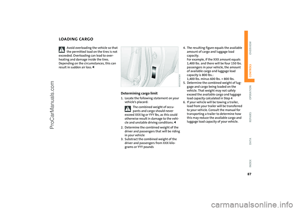
Determining cargo limit1. Locate the following statement on your
vehicle's placard:
The combined weight of occu
-
pants and cargo should never
exceed XXX
kg or YYY
lbs, as this could
otherwise result in damage to the vehi
-
cle and unstable driving conditions.<
2. Determine the combined weight of the
driver and passengers that will be riding
in your vehicle3. Substract the combined weight of the
driver and passengers from XXX kilo
-
grams or YYY
pounds
4. The resulting figure equals the available
amount of cargo and luggage load
capacity.
For example, if the XXX amount equals
1,400 lbs. and there will be four 150
lbs.
passengers in your vehicle, the amount
of available cargo and luggage load
capacity is 800
lbs.:
1,400
lbs. minus 600
lbs. = 800
lbs.
5. Determine the combined weight of lug
-
gage and cargo being loaded on the
vehicle. That weight may not safely
exceed the available cargo and luggage
load capacity calculated in Step
4
6. If your vehicle will be towing a trailer,
load from your trailer will be transferred
to your vehicle. Consult the manual for
transporting a trailer to determine how
this may reduce the available cargo and
luggage load capacity of your vehicle.
ProCarManuals.com
Page 91 of 165
89
OVERVIEW REPAIRS OPERATIONCONTROLS DATA INDEX
ROOF-MOUNTED LUGGAGE RACK
*
Always position and secure the load as described above. If you do not, it
can pose a danger to the passengers during
braking and evasive maneuvers, for exam
-
ple.
Do not exceed the permissible gross weight
and axle load, refer to page
143
ff; other
-
wise the vehicle's operating safety is no
longer assured and it will not be in compli
-
ance with the certification regulations.
Do not stow heavy or hard objects in the
passenger compartment without first
securing them. Otherwise they would be
thrown around during braking and evasive
maneuvers and endanger the occupants.<
When loading a roof-mounted lug
-
gage rack on the MINI, make sure
that there is sufficient space for the move
-
ment of the glass sunroof and that no
objects protrude into the swiveling area of
the tailgate, as otherwise damage can
occur. Do not secure the roof-mounted lug
-
gage rack to the MINI's trim strips or to the
MINI Convertible top. Otherwise, the lack
of a secure hold could lead to damage or
accidents.<
Special roof-mounted luggage racks for your MINI are available as acces
-
sories from your MINI Dealer.<
ProCarManuals.com
Page 93 of 165
OVERVIEW
CONTROLS
OPERATION, CARE, MAINTENANCE
OWNER SERVICE PROCEDURES
INDEX TECHNICAL DATA
91
OVERVIEW REPAIRSOPERATIONCONTROLS DATA INDEX
Operation
ProCarManuals.com
Page 95 of 165

93
OVERVIEW REPAIRSOPERATIONCONTROLS DATA INDEX
GENERAL DRIVING NOTESParking the vehicle Condensation forms in the air conditioner
system during operation, and then exits
under the vehicle. Traces of condensed
water on the ground are therefore normal.Safe braking Your vehicle is equipped with ABS as a stan
-
dard feature. The best way to brake the
vehicle in critical situations requiring brak
-
ing is to apply maximum pressure to the
brake pedal: panic stop. Since the vehicle
remains maneuverable, you can still go
around any obstacles with the smallest
possible steering movements. The pulsation of the brake pedal, together
with the sound of hydraulic regulation,
indicates to you that ABS is actively taking
effect. Hydroplaning
When driving on wet or slushy roads, reduce road speed. If you do not, a
wedge of water can form between tires
and road surface. This phenomenon is char
-
acterized by a partial or complete loss of
contact between the tires and the road sur
-
face. The ultimate results are loss of steer
-
ing and braking control.<
Mobile communications in the vehicle
The manufacturer of your MINI
recommends that you do not use
mobile devices, e.g. cellular phones, inside
the vehicle without directly connecting
them to an outside antenna. Otherwise,
interference between the vehicle electron
-
ics and the mobile device cannot be ruled
out. In addition, it is not ensured that the
radiation emitted during mobile transmis
-
sion will be directed outside of the vehi
-
cle.
ft / 30 cm,
and then only at walking speed at the
most. Otherwise, the vehicle's engine, the
electrical systems and the transmission
may be damaged.<
Clothes hooks
When suspending clothing from the hooks, ensure that they will not
obstruct the driver's vision. Do not hang
heavy objects on the hooks. If you do, they
could injure the occupants during braking
or evasive maneuvers.<
Hot exhaust system
High temperatures occur in any vehi
-
cle equipped with a catalytic con
-
verter. Do not remove the heat protection
plates fitted in the area of the exhaust sys
-
tem and do not apply body-cavity pro
-
tectant to this area. When driving, standing
at idle, and parking the vehicle, take care to
avoid contact between the hot exhaust sys
-
tem and flammable materials, e.g. hay,
grass, leaves, etc. Such contact could lead
to a fire resulting in serious personal injury
and property damage.<
ProCarManuals.com
Page 97 of 165
95
OVERVIEW REPAIRSOPERATIONCONTROLS DATA INDEX
REFUELING
Do not use leaded gasoline, as other
-
wise the lambda probe and catalytic
converter will be permanently damaged.<
Use high-quality brandsField experience has indicated significant
differences in fuel quality: volatility, com
-
position, additives, etc., among gasolines
offered for sale in the United States and
Canada. Fuels containing up to and includ
-
ing 10
% ethanol or other oxygenates with
up to 2.8 % oxygen by weight, that is, 15
%
MTBE or 3% methanol plus an equivalent
amount of co-solvent, will not void the
applicable warranties with respect to
defects in materials or workmanship.
The use of poor-quality fuels may result in driveability, starting and
stalling problems especially under certain
environmental conditions such as high
ambient temperature and high altitude.
Should you encounter driveability prob
-
lems which you suspect could be related to
the fuel you are using, we recommend that
you respond by switching to a recognized
high-quality brand.
Failure to comply with these recommenda
-
tions may result in unscheduled mainte
-
nance.<
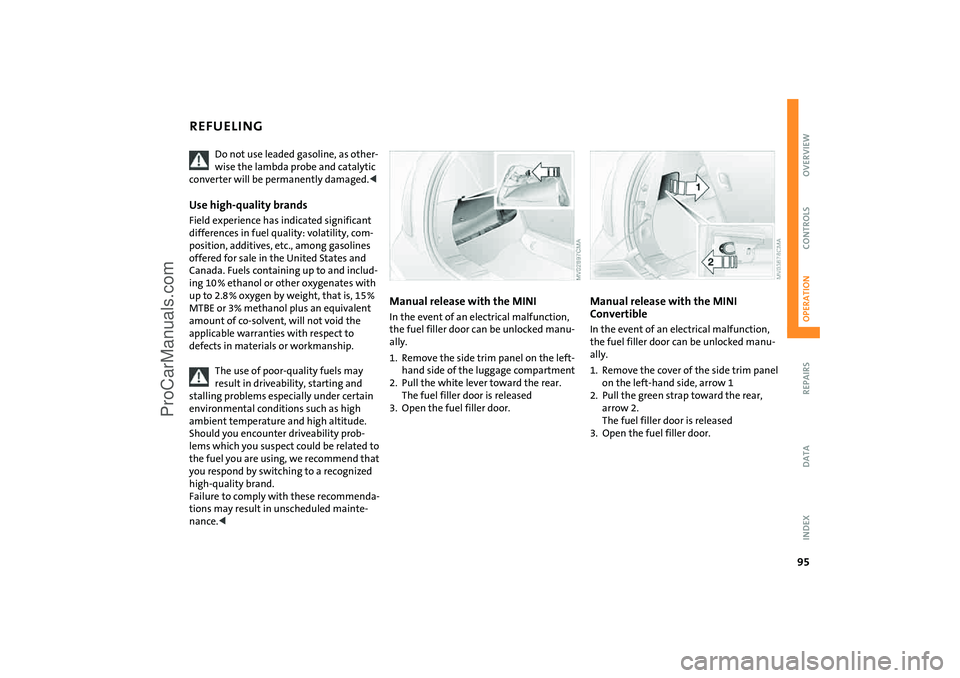
Manual release with the MINI In the event of an electrical malfunction,
the fuel filler door can be unlocked manu
-
ally.1. Remove the side trim panel on the left-
hand side of the luggage compartment2. Pull the white lever toward the rear.
The fuel filler door is released
3. Open the fuel filler door.
Manual release with the MINI Convertible In the event of an electrical malfunction,
the fuel filler door can be unlocked manu
-
ally.1. Remove the cover of the side trim panel
on the left-hand side, arrow
1
2. Pull the green strap toward the rear,
arrow
2.
The fuel filler door is released
3. Open the fuel filler door.
ProCarManuals.com