ESP MINI COOPER 2013 Owners Manual
[x] Cancel search | Manufacturer: MINI, Model Year: 2013, Model line: COOPER, Model: MINI COOPER 2013Pages: 267, PDF Size: 3.53 MB
Page 7 of 267
Notes
6
>California Emission Control System Limited
Warranty
Detailed information about these warranties is
listed in the Service and Warranty Information
Booklet for US models or in the Warranty and
Service Guide Booklet for Canadian models.
Your vehicle has been specifically adapted and
designed to meet the pa rticular operating con-
ditions and registration requirements in your
country and continental region in order to
deliver the full driving pleasure while the vehicle
is operated under those conditions. If you wish
to operate your vehicle in another country or
region, you may be required to adapt your vehi-
cle to meet different prevailing operating condi-
tions and registration re quirements. You should
also be aware of any a pplicable warranty limita-
tions or exclusions for such country or region. In
such a case, please contact Customer Relations
for further information.
Maintenance
Maintain the vehicle regularly to sustain road
safety, operational reliab ility and the New Vehi-
cle Limited Warranty.
Specifications for required maintenance mea-
sures:
> MINI Maintenance System
> Service and Warranty Information Booklet
for US models
> Warranty and Service Guide Booklet for
Canadian models
If the vehicle is not ma intained according to
these specifications, this could result in serious
damage to the vehicle. Such damage is not cov-
ered by the MINI New Vehicle Limited Warranty.
Data memory
A variety of electronic components in your vehi-
cle include data storage devices, which store
technical information on the condition of your
vehicle, events and errors, either temporarily or
permanently. In general, this technical informa- tion documents the condition of a component, a
module, a system or
the surroundings:
> Operating conditions of system compo-
nents, e.g., fill levels.
> Status messages regarding the vehicle and
of its individual comp onents, such as wheel
rpm/vehicle speed, response delay, lateral
acceleration.
> Malfunctions and defects in the major sys-
tem components, such as the lights and
brakes.
> Responses of the vehicle in special driving
situations, such as the deployment of an air-
bag, the utilization of stability control sys-
tems.
> Environmental conditio ns, such as tempera-
ture.
These data are exclusively of a technical nature
and are used for the detection and correction of
errors, as well as the optimization of vehicle
functions. Motion profiles of traveled routes can
not be deduced from these data. If services are
required, such as repair services, service pro-
cesses, warranty claims an d quality assurance,
then this technical info rmation can be read out
by employees of service departments, including
the manufacturer, from the event and error data
storage devices by usin g special diagnostic
equipment. There, if necessary, you will receive
further information. Afte r remedying an error,
the information in the error memory is deleted
or progressively overwritten.
When using the vehicle, situations are conceiv-
able in which this techni cal data, in conjunction
with other information, su ch as accident reports,
vehicle damage, witness statements, etc. - pos-
sibly with the assistance of an expert - could be
traced to particular individuals. Additional func-
tions that are agreed upon contractually with
the customer, such as vehi cle tracking in case of
emergency, permit the transmission of certain
vehicle data from the vehicle.
00320051004F004C00510048000300280047004C0057004C005200510003
Page 14 of 267
CockpitAT A GLANCE
13
Indicator and warning
lamps
The concept
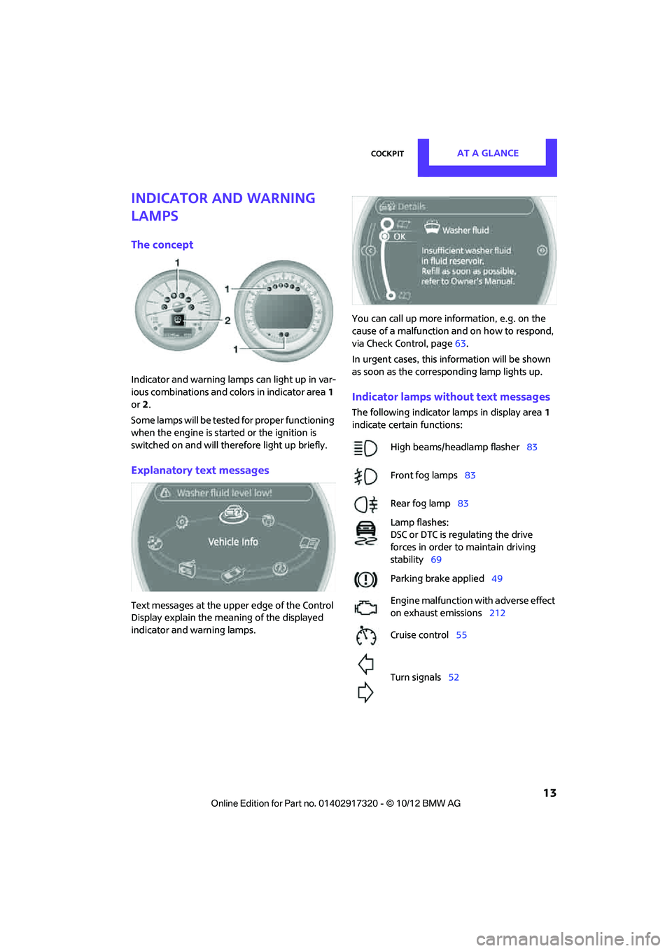
Indicator and warning lamps can light up in var-
ious combinations and colors in indicator area1
or 2.
Some lamps will be tested for proper functioning
when the engine is started or the ignition is
switched on and will therefore light up briefly.
Explanatory text messages
Text messages at the uppe r edge of the Control
Display explain the mean ing of the displayed
indicator and warning lamps. You can call up more information, e.g. on the
cause of a malfunction and on how to respond,
via Check Control, page
63.
In urgent cases, this information will be shown
as soon as the corresponding lamp lights up.
Indicator lamps without text messages
The following indicator lamps in display area 1
indicate certain functions:
High beams/headlamp flasher 83
Front fog lamps 83
Rear fog lamp 83
Lamp flashes:
DSC or DTC is regulating the drive
forces in order to maintain driving
stability 69
Parking brake applied 49
Engine malfunction with adverse effect
on exhaust emissions 212
Cruise control 55
Turn signals 52
00320051004F004C00510048000300280047004C0057004C005200510003
Page 23 of 267
AT A GLANCEVoice activation system
22
Possible commands
Most menu items on the Control Display can be
spoken as commands.
The commands that are possible depend upon
which menu is currently shown on the Control
Display.
There are short commands for many functions.
Some list items, for example telephone book
listings, can also be selected using the voice acti-
vation system. In particular, say the list items
exactly as they are displayed in the respective
list.
Having the possible commands read
aloud
Having the possible co mmands read aloud:
For example if you have selected "CD" the sys-
tem will read aloud the possible commands for
operating the CD player.
Carrying out functions through short
commands
Main menu functions can be executed immedi-
ately by short commands , almost regardless of
which menu item is selected, e.g., {Vehicle sta-
tus }.
List of voice activation system short commands,
see page 245.
Help for the voice activation system
Calling up Help:
Additional commands for Help:
>{Help with examples }: information about
the current operating options and the most
important commands for them are
announced.
> {Help with voice activation }: information
regarding the principles behind the voice
activation system is announced.
Using alternative commands
There are often a number of commands to run a
function, e.g.:
Opening the main menu
Example: playing a CD
Via the main menu
The commands of the menu items are spoken
aloud; they can also be selected using the MINI
joystick.
1. Switch on Entertainment sound output if
necessary.
2. Press the button on the steering wheel.
Via short commands
The CD playback can also be started by a short
command.
1.Switch on Entertainment sound output if
necessary.
2. Press the button on the steering wheel.
3. {C D … track … } e.g. CD track 4.
Setting the voice dialog
You can set whether the system uses the stan-
dard dialog or a short version.
With the short version of the spoken dialog, a
shortened version of the requests and responses
of the voice activation system are played aloud.
1. "Settings"
2. "Language/Units"
{
Voice commands }
{ Help }
{Radio } or {Radio on }
{ Main menu }
3. {{C D and multimedia }}
4. {C D }
5. {C D track … }
6. {{Track … }}e.g. CD track 4.
00320051004F004C00510048000300280047004C0057004C005200510003
Page 27 of 267
CONTROLSOpening and closing
26
Opening and closing
Vehicle equipment
In this chapter, all production, country, and
optional equipment that is offered in the model
range is described. Equipment is also described
that is not available because of, for example,
selected options or coun try version. This also
applies to safety relate d functions and systems.
Keys/remote controls
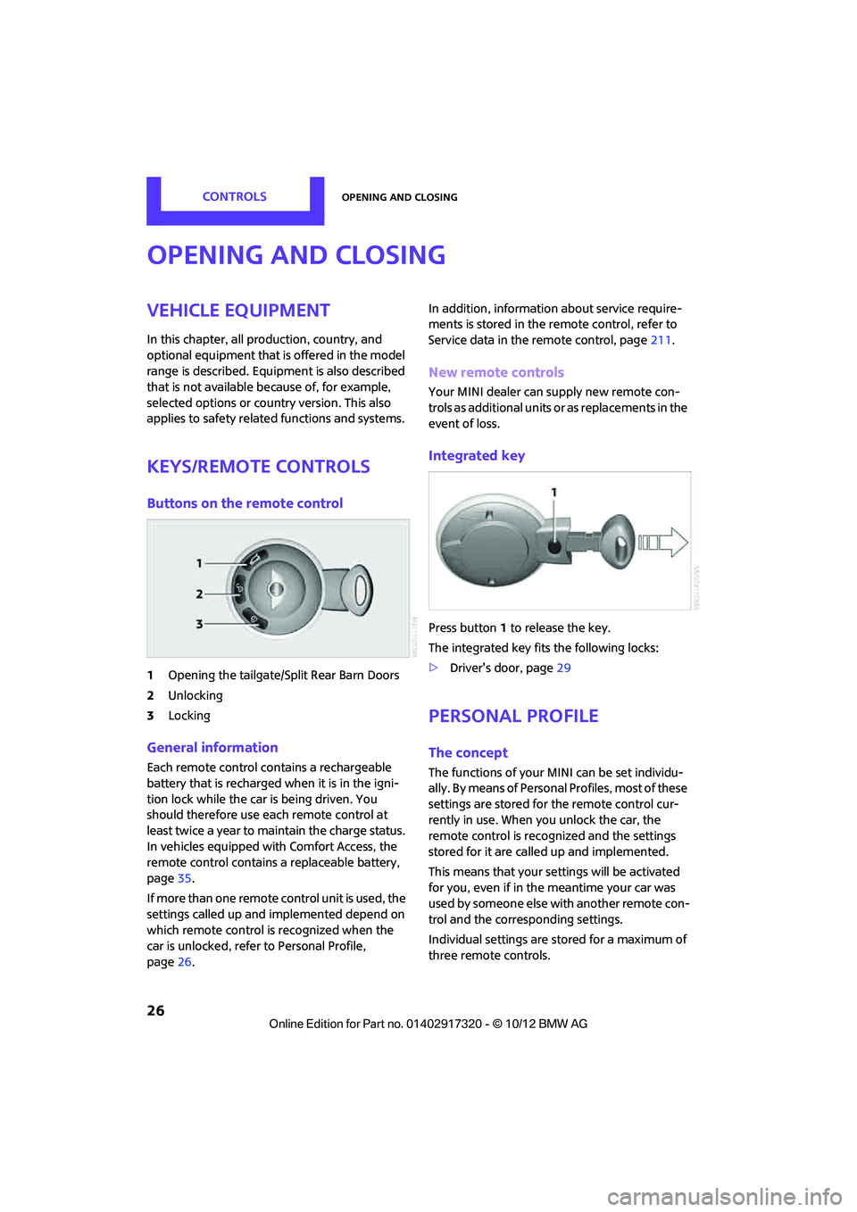
Buttons on the remote control
1Opening the tailgate/Split Rear Barn Doors
2 Unlocking
3 Locking
General information
Each remote control co ntains a rechargeable
battery that is recharged when it is in the igni-
tion lock while the car is being driven. You
should therefore use each remote control at
least twice a year to maintain the charge status.
In vehicles equipped with Comfort Access, the
remote control contains a replaceable battery,
page 35.
If more than one remote control unit is used, the
settings called up and implemented depend on
which remote control is recognized when the
car is unlocked, refer to Personal Profile,
page 26. In addition, information about service require-
ments is stored in the remote control, refer to
Service data in the remote control, page
211.
New remote controls
Your MINI dealer can supply new remote con-
trols as additional units or as replacements in the
event of loss.
Integrated key
Press button1 to release the key.
The integrated key fits the following locks:
> Driver's door, page 29
Personal Profile
The concept
The functions of your MINI can be set individu-
ally. By means of Personal Profiles, most of these
settings are stored for the remote control cur-
rently in use. When you unlock the car, the
remote control is recognized and the settings
stored for it are called up and implemented.
This means that your settings will be activated
for you, even if in the meantime your car was
used by someone else with another remote con-
trol and the corresponding settings.
Individual settings are stored for a maximum of
three remote controls.
00320051004F004C00510048000300280047004C0057004C005200510003
Page 28 of 267

Opening and closingCONTROLS
27
Personal Profile settings
For more information on specific settings, refer
to the specified pages.
> Response of the central locking system
when the car is being unlocked 27
> Automatic locking of the vehicle 30
> Triple turn signal activation 52
> Settings for the displays on the onboard
computer, in the speedometer and in the
tachometer:
>12 h/24 h mode of the clock 63
> Date format 63
> Brightness of the Control Display 66
> Language on the Control Display 66
> Units of measure for fuel consumption,
distance covered/re maining distances
and temperature 60
> Light settings:
>Pathway lighting 82
> Daytime running lights 82
> Automatic climate control: activating/deac-
tivating the AUTO program, setting the tem-
perature, air volume and air distribution 87
> Entertainment:
>Tone control 133
> Adjusting vo lume levels 133
Central lock ing system
The concept
The central locking system is ready for operation
whenever the driver's door is closed.
The system simultaneously engages and
releases the locks on the following:
>Doors
> MINI: tailgate
> MINI Clubman: Split Rear Barn Doors
> Fuel filler flap
Operating from outside
>Via the remote control
> Using the door lock
> In cars with Comfor t Access, via the door
handles on the driver's and passenger's
sides
The anti-theft system is also operated at the
same time. It prevents the doors from being
unlocked using the lock buttons or door han-
dles. The remote control can also be used to
switch the welcome lamps, the interior light, and
the ambient lighting on and off. The alarm sys-
tem is also activated or deactivated, page 32.
Operating from inside
Button for central locking system, page 30.
In the event of a sufficiently severe accident, the
central locking system unlocks automatically. In
addition, the hazard warning flashers and inte-
rior lamps come on.
Opening and closing:
from outside
Persons or animals in a parked vehicle
could lock the doors from the inside. Take
the key with you when you leave the vehicle so
that the vehicle can be opened from the out-
side. <
Using the remote control
Unlocking
Press the button.
The welcome lamps and interior lamps come on.
Unlocking mode
You can also set which parts of the car are
unlocked. The setting is stored for the remote
control in use.
00320051004F004C00510048000300280047004C0057004C005200510003
Page 35 of 267
CONTROLSOpening and closing
34
>The engine can only be started if the remote
control is in the vehicle.
> The doors and tailgate/Split Rear Barn Doors
must be closed to be able to operate the
windows and glass roof.
Comparison to standard remote controls
The indicated function can be operated by
pressing the buttons or via Comfort Access.
Instructions on opening and closing are found
starting on page 26.
If you notice a brief delay while opening or
closing the windows or glass roof, the sys-
tem is checking whether a remote control is
inside the vehicle. Repeat the opening or closing
procedure, if necessary. <
Unlocking
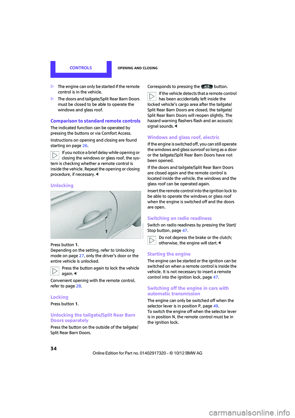
Press button 1.
Depending on the setting, refer to Unlocking
mode on page 27, only the driver's door or the
entire vehicle is unlocked.
Press the button again to lock the vehicle
again. <
Convenient opening with the remote control,
refer to page 28.
Locking
Press button 1.
Unlocking the tailgate/Split Rear Barn
Doors separately
Press the button on the outside of the tailgate/
Split Rear Barn Doors. Corresponds to pressing the button.
If the vehicle detects that a remote control
has been accidentally left inside the
locked vehicle's cargo area after the tailgate/
Split Rear Barn Doors are closed, the tailgate/
Split Rear Barn Doors will reopen slightly. The
hazard warning flashers flash and an acoustic
signal sounds. <
Windows and glass roof, electric
If the engine is switched off, you can still operate
the windows and glass sunr oof so long as a door
or the tailgate/Split Rear Barn Doors have not
been opened.
If the doors and tailgate /Split Rear Barn Doors
are closed again and th e remote control is
located inside the vehicle, the windows and the
glass roof can be operated again.
Insert the remote control into the ignition lock to
be able to operate the windows or glass roof
when the engine is swit ched off and the doors
are open.
Switching on radio readiness
Switch on radio readines s by pressing the Start/
Stop button, page 47.
Do not depress the brake or the clutch;
otherwise, the engine will start. <
Starting the engine
The engine can be started or the ignition can be
switched on when a remote control is inside the
vehicle. It is not necessary to insert a remote
control into the ignition lock, page 47.
Switching off the engine in cars with
automatic transmission
The engine can only be switched off when the
selector lever is in position P, page 49.
To switch the engine off when the selector lever
is in position N, the remote control must be in
the ignition lock.
00320051004F004C00510048000300280047004C0057004C005200510003
Page 40 of 267
AdjustmentsCONTROLS
39
ing and regularly pull the belt in the upper-body
area taut; otherwise, its restraining effect could
be impaired. <
Safety belts, refer to page 41.
Seats
Note before adjusting
Never attempt to adjust your seat while
the vehicle is moving. The seat could
respond with unexpected movement, and the
ensuing loss of vehicle control could lead to an
accident.
On the front passenger seat as well, do not
incline the backrest too far to the rear while the
vehicle is being driven; otherwise, there is a dan-
ger in the event of an a ccident of sliding under
the safety belt, eliminat ing the protection nor-
mally provided by the belt. <
Comply with the instruct ions on head restraint
height on page 40 and on damaged safety belts
on page 42.
Seat adjustment
Observe the instructions on page 39 to
ensure the best possible personal protec-
tion. <
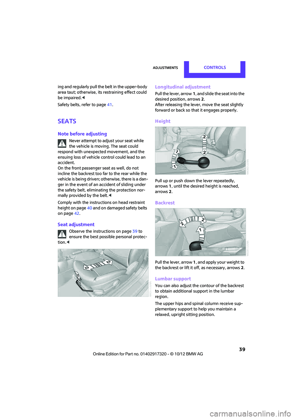
Longitudinal adjustment
Pull the lever, arrow 1, and slide the seat into the
desired position, arrows 2.
After releasing the lever, move the seat slightly
forward or back so that it engages properly.
Height
Pull up or push down the lever repeatedly,
arrows 1, until the desired height is reached,
arrows 2.
Backrest
Pull the lever, arrow 1, and apply your weight to
the backrest or lift it off, as necessary, arrows 2.
Lumbar support
You can also adjust the contour of the backrest
to obtain additional support in the lumbar
region.
The upper hips and spinal column receive sup-
plementary support to help you maintain a
relaxed, upright sitting position.
00320051004F004C00510048000300280047004C0057004C005200510003
Page 59 of 267
CONTROLSControls overview
58
The following information is displayed sequen-
tially:
>Trip odometer
> Time
> External temperature
Trip odometer
To display trip recorder:
Briefly press button 3.
Resetting the trip odometer:
While the trip recorder is displayed and the igni-
tion is switched on, press button 3.
Time
To set time, see page 62.
External temperature, external
temperature warning
When the displayed temperature sinks to
approx. +37 7/+3 6, a signal sounds and a
warning lamp lights up. There is an increased
risk of black ice.
Even at temperatures above +37 7/+3 6
ice can form. Therefore, drive carefully,
e.g. on bridges and sect ions of road in the
shade; otherwise, there is an increased accident
risk. <
Units of measure
Select the respective units of measure, miles or
km for the odometer as well as 7 or 6 for the
external temperature, page 60.
Computer
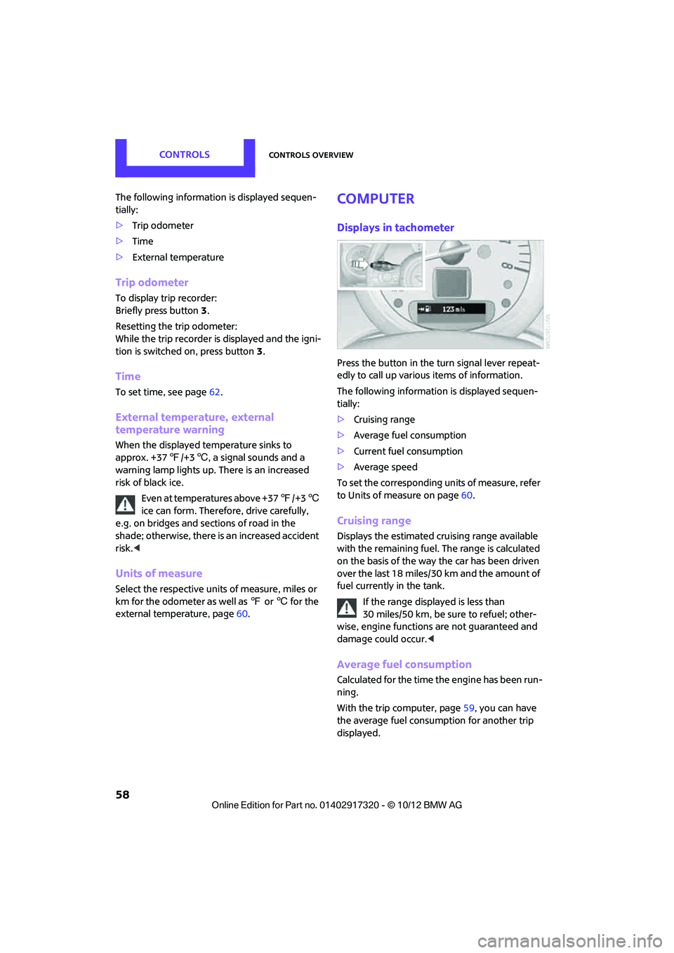
Displays in tachometer
Press the button in the turn signal lever repeat-
edly to call up various items of information.
The following information is displayed sequen-
tially:
> Cruising range
> Average fuel consumption
> Current fuel consumption
> Average speed
To set the corresponding units of measure, refer
to Units of measure on page 60.
Cruising range
Displays the estimated cruising range available
with the remaining fuel. The range is calculated
on the basis of the way the car has been driven
over the last 18 miles/30 km and the amount of
fuel currently in the tank.
If the range displayed is less than
30 miles/50 km, be sure to refuel; other-
wise, engine functions are not guaranteed and
damage could occur. <
Average fuel consumption
Calculated for the time the engine has been run-
ning.
With the trip computer, page 59, you can have
the average fuel consum ption for another trip
displayed.
00320051004F004C00510048000300280047004C0057004C005200510003
Page 60 of 267
Controls overviewCONTROLS
59
To reset average fuel consumption: press the
button in the turn signal lever for approx.
2 seconds.
Current fuel consumption
Displays the current fuel consumption to allow
you to see whether your current driving style is
conducive to fuel economy with minimum
exhaust emissions.
Average speed
Periods with the vehicle parked and the engine
switched off are not included in the calculations
of average speed.
With the trip computer, page59, you can have
the average speed for another trip displayed.
To reset average speed: press the button in the
turn signal lever fo r approx. 2 seconds.
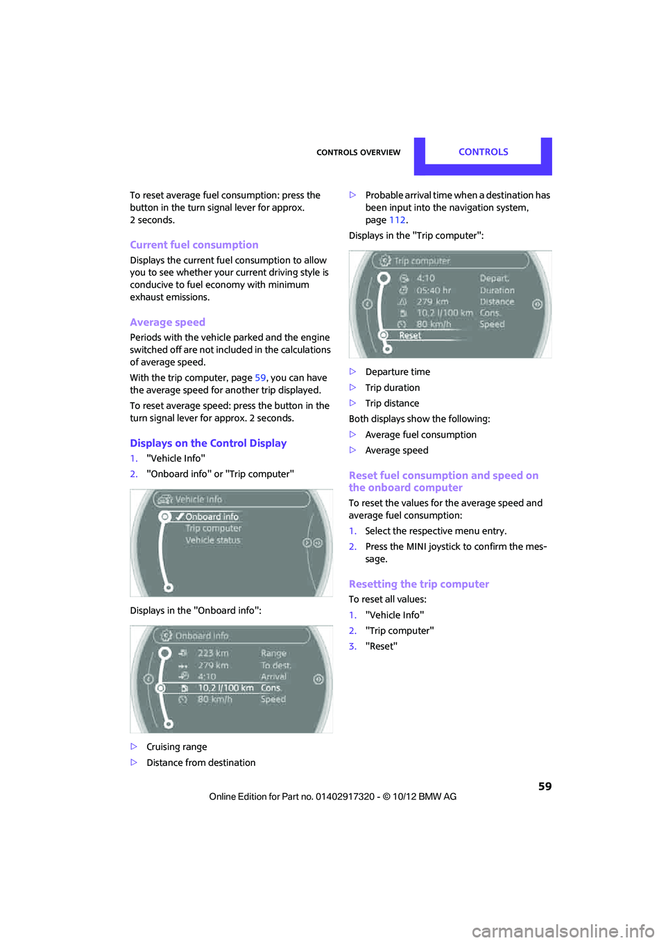
Displays on the Control Display
1."Vehicle Info"
2. "Onboard info" or "Trip computer"
Displays in the "Onboard info":
> Cruising range
> Distance from destination >
Probable arrival time when a destination has
been input into the navigation system,
page 112.
Displays in the "Trip computer":
> Departure time
> Trip duration
> Trip distance
Both displays show the following:
> Average fuel consumption
> Average speed
Reset fuel consumption and speed on
the onboard computer
To reset the values for the average speed and
average fuel consumption:
1.Select the respective menu entry.
2. Press the MINI joystick to confirm the mes-
sage.
Resetting the trip computer
To reset all values:
1."Vehicle Info"
2. "Trip computer"
3. "Reset"
00320051004F004C00510048000300280047004C0057004C005200510003
Page 65 of 267
CONTROLSControls overview
64
Text messages
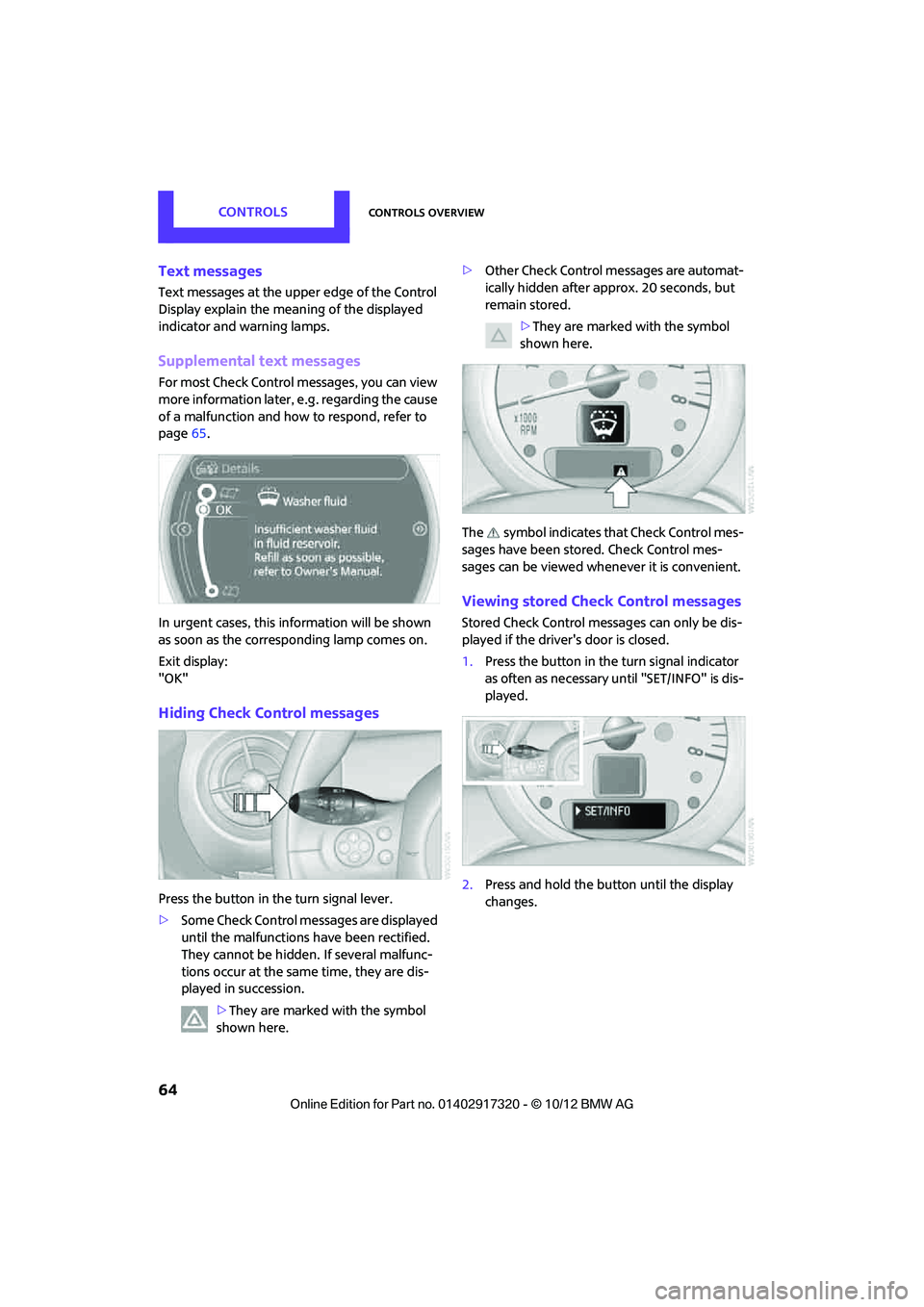
Text messages at the upper edge of the Control
Display explain the mean ing of the displayed
indicator and warning lamps.
Supplemental text messages
For most Check Control messages, you can view
more information later, e.g. regarding the cause
of a malfunction and how to respond, refer to
page 65.
In urgent cases, this information will be shown
as soon as the corresponding lamp comes on.
Exit display:
"OK"
Hiding Check Control messages
Press the button in th e turn signal lever.
> Some Check Control me ssages are displayed
until the malfunctions have been rectified.
They cannot be hidden. If several malfunc-
tions occur at the same time, they are dis-
played in succession.
>They are marked with the symbol
shown here. >
Other Check Control messages are automat-
ically hidden after approx. 20 seconds, but
remain stored.
>They are marked with the symbol
shown here.
The symbol indicates that Check Control mes-
sages have been stor ed. Check Control mes-
sages can be viewed whenever it is convenient.
Viewing stored Check Control messages
Stored Check Control me ssages can only be dis-
played if the driver's door is closed.
1. Press the button in the turn signal indicator
as often as necessary until "SET/INFO" is dis-
played.
2. Press and hold the button until the display
changes.
00320051004F004C00510048000300280047004C0057004C005200510003