warning MINI Countryman 2015 Owner's Manual (Mini Connected)
[x] Cancel search | Manufacturer: MINI, Model Year: 2015, Model line: Countryman, Model: MINI Countryman 2015Pages: 283, PDF Size: 6.76 MB
Page 9 of 283
sary to adapt your vehicle to potentially differ‐
ing operating conditions and permit
requirements. If your vehicle does not comply
with the homologation requirements in a cer‐
tain country you cannot lodge warranty claims
for your vehicle there. Further information can
be obtained from your Service Center.
Maintenance and repairs Advanced technology, e.g., the use of modern
materials and high-performance electronics,
requires suitable maintenance and repair
methods.
Therefore, have this work performed only by a
MINI service center or a workshop that works
according to MINI repair procedures with ap‐
propriately trained personnel.
If this work is not carried out properly, there is
the danger of subsequent damage and related
safety hazards.
Parts and accessories
For your own safety, it is recommended that
you use genuine parts and accessories ap‐
proved by MINI. When you purchase accesso‐
ries tested and approved by MINI and Genuine
MINI Parts, you simultaneously acquire the as‐
surance that they have been thoroughly tested
by MINI to ensure optimum performance when
installed on your vehicle. MINI warrants these
parts to be free from defects in material and
workmanship. MINI will not accept any liability
for damage resulting from installation of parts
and accessories not approved by MINI. MINI
cannot test every product made by other man‐
ufacturers to verify if it can be used on a MINI
safely and without risk to either the vehicle, its
operation, or its occupants. Genuine MINI Parts,
MINI Accessories and other products approved
by MINI, together with professional advice on
using these items, are available from all MINI
centers. Installation and operation of non MINI
approved accessories such as alarms, radios,
amplifiers, radar detectors, wheels, suspension
components, brake dust shields, telephones,including operation of any mobile phone from
within the vehicle without using an externally
mounted antenna, or transceiver equipment,
for instance, CBs, walkie-talkies, ham radios or
similar accessories, may cause extensive dam‐
age to the vehicle, compromise its safety, inter‐
fere with the vehicle's electrical system or af‐
fect the validity of the MINI Limited Warranty.
See your MINI center for additional informa‐
tion. Maintenance, replacement, or repair of
the emission control devices and systems may
be performed by any automotive repair estab‐
lishment or individual using any certified auto‐
motive part.
California Proposition 65 Warning California laws require us to state the following
warning:
Engine exhaust and a wide variety of automo‐
bile components and parts, including compo‐
nents found in the interior furnishings in a vehi‐
cle, contain or emit chemicals known to the
State of California to cause cancer and birth de‐
fects and reproductive harm. In addition, cer‐
tain fluids contained in vehicles and certain
products of component wear contain or emit
chemicals known to the State of California to
cause cancer and birth defects or other repro‐
ductive harm. Battery posts, terminals and re‐
lated accessories contain lead and lead com‐
pounds. Wash your hands after handling. Used
engine oil contains chemicals that have caused
cancer in laboratory animals. Always protect
your skin by washing thoroughly with soap and
water.
Service and warranty
We recommend that you read this publication
thoroughly. Your vehicle is covered by the fol‐
lowing warranties:▷New Vehicle Limited Warranty.▷Rust Perforation Limited Warranty.▷Federal Emissions System Defect Warranty.▷Federal Emissions Performance Warranty.Seite 7Notes7
Online Edition for Part no. 01 40 2 961 110 - II/15
Page 16 of 283
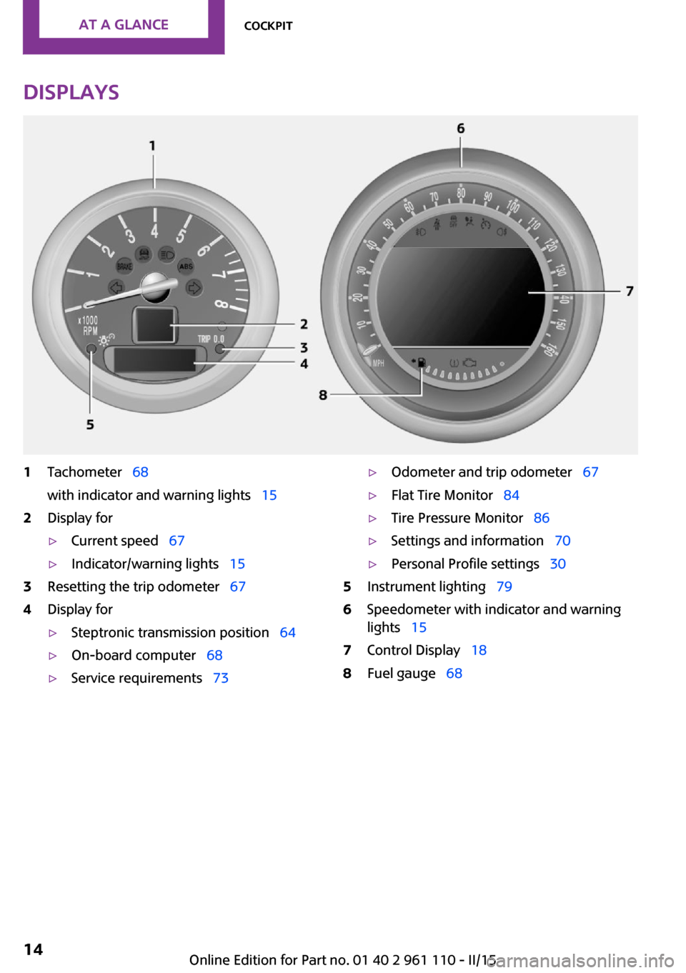
Displays1Tachometer 68
with indicator and warning lights 152Display for▷Current speed 67▷Indicator/warning lights 153Resetting the trip odometer 674Display for▷Steptronic transmission position 64▷On-board computer 68▷Service requirements 73▷Odometer and trip odometer 67▷Flat Tire Monitor 84▷Tire Pressure Monitor 86▷Settings and information 70▷Personal Profile settings 305Instrument lighting 796Speedometer with indicator and warning
lights 157Control Display 188Fuel gauge 68Seite 14AT A GLANCECockpit14
Online Edition for Part no. 01 40 2 961 110 - II/15
Page 17 of 283
Indicator/warning lights
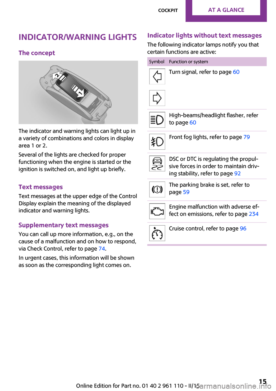
The concept
The indicator and warning lights can light up in
a variety of combinations and colors in display
area 1 or 2.
Several of the lights are checked for proper
functioning when the engine is started or the
ignition is switched on, and light up briefly.
Text messages
Text messages at the upper edge of the Control
Display explain the meaning of the displayed
indicator and warning lights.
Supplementary text messages
You can call up more information, e.g., on the
cause of a malfunction and on how to respond,
via Check Control, refer to page 74.
In urgent cases, this information will be shown
as soon as the corresponding light comes on.
Indicator lights without text messages
The following indicator lamps notify you that
certain functions are active:SymbolFunction or systemTurn signal, refer to page 60High-beams/headlight flasher, refer
to page 60Front fog lights, refer to page 79DSC or DTC is regulating the propul‐
sive forces in order to maintain driv‐
ing stability, refer to page 92The parking brake is set, refer to
page 59Engine malfunction with adverse ef‐
fect on emissions, refer to page 234Cruise control, refer to page 96Seite 15CockpitAT A GLANCE15
Online Edition for Part no. 01 40 2 961 110 - II/15
Page 18 of 283
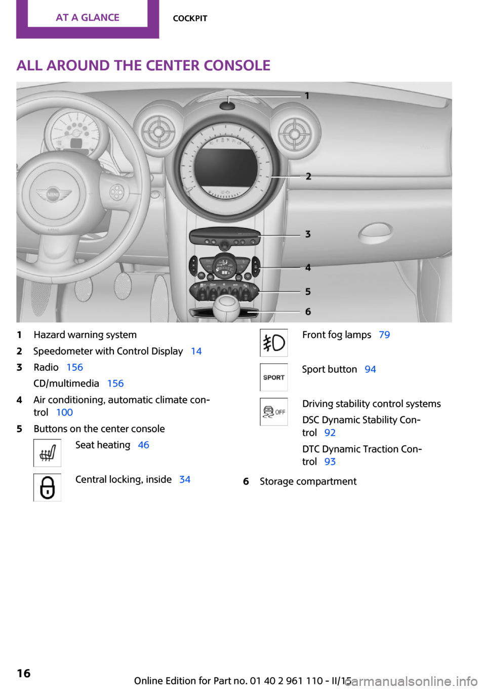
All around the center console1Hazard warning system2Speedometer with Control Display 143Radio 156
CD/multimedia 1564Air conditioning, automatic climate con‐
trol 1005Buttons on the center consoleSeat heating 46Central locking, inside 34Front fog lamps 79Sport button 94Driving stability control systems
DSC Dynamic Stability Con‐
trol 92
DTC Dynamic Traction Con‐
trol 936Storage compartmentSeite 16AT A GLANCECockpit16
Online Edition for Part no. 01 40 2 961 110 - II/15
Page 19 of 283
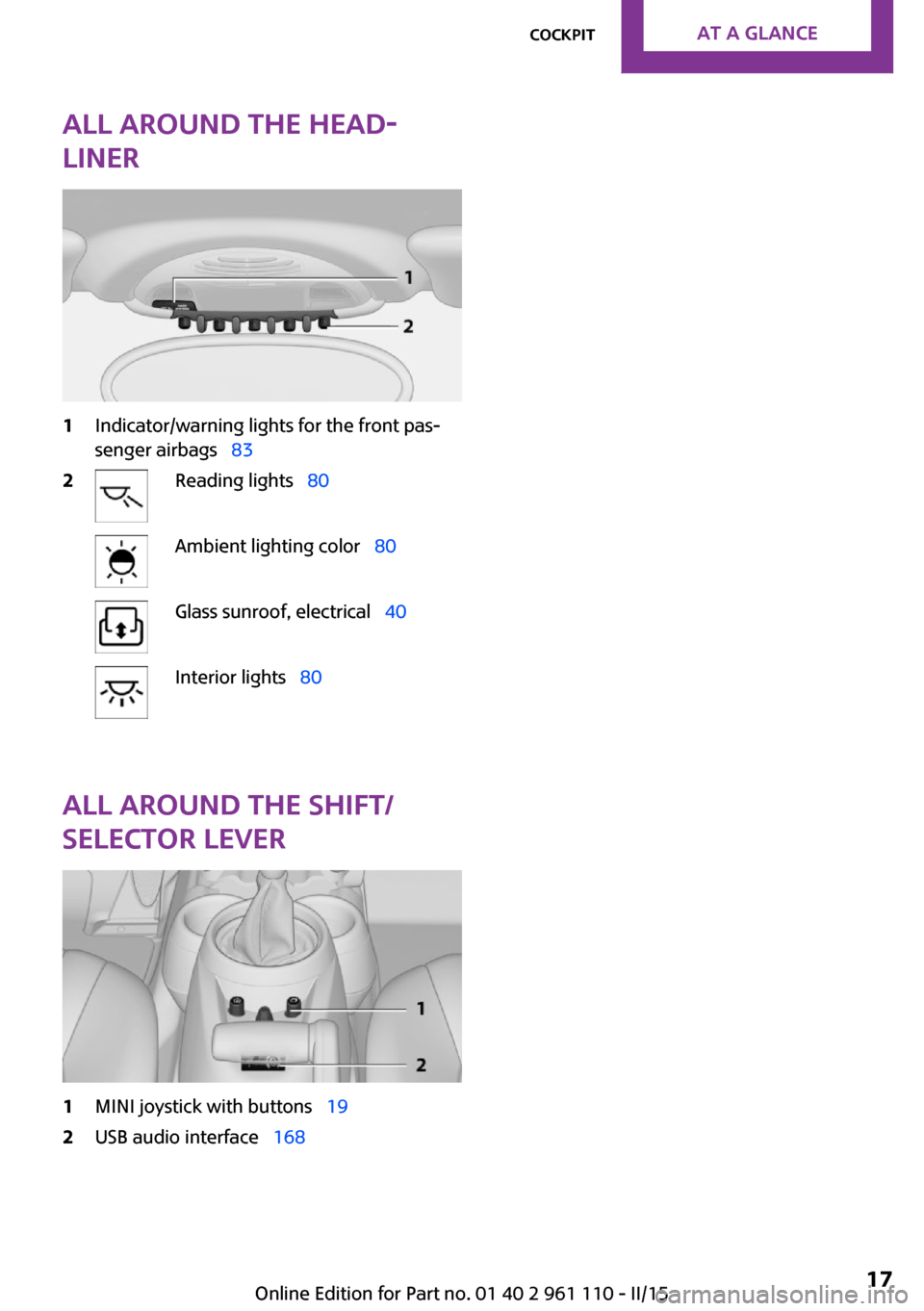
All around the head‐
liner1Indicator/warning lights for the front pas‐
senger airbags 832Reading lights 80Ambient lighting color 80Glass sunroof, electrical 40Interior lights 80
All around the shift/
selector lever
1MINI joystick with buttons 192USB audio interface 168Seite 17CockpitAT A GLANCE17
Online Edition for Part no. 01 40 2 961 110 - II/15
Page 34 of 283
Operating from the insideVia the switch/button for the central locking
system, refer to page 34.
In an accident of the necessary severity, the
central locking system unlocks automatically.
The hazard warning system and interior lamps
come on.
Opening and closing:
from the outside
Using the remote control
General information Take the remote control with you
People or animals left unattended in a
parked vehicle can lock the doors from the in‐
side. Always take the remote control with you
when leaving the vehicle so that the vehicle
can then be opened from the outside. ◀
Unlocking
Press the button. The vehicle is un‐
locked.
The welcome lamps and interior lamps are
switched on.
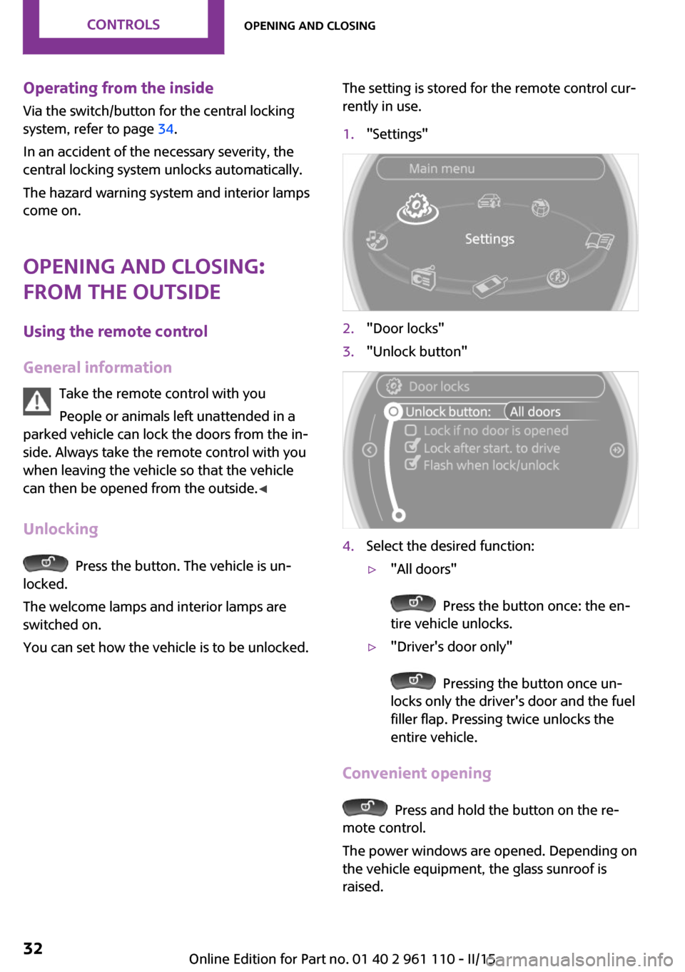
You can set how the vehicle is to be unlocked.
The setting is stored for the remote control cur‐
rently in use.1."Settings"2."Door locks"3."Unlock button"4.Select the desired function:▷"All doors"
Press the button once: the en‐
tire vehicle unlocks.
▷"Driver's door only"
Pressing the button once un‐
locks only the driver's door and the fuel
filler flap. Pressing twice unlocks the
entire vehicle.
Convenient opening
Press and hold the button on the re‐
mote control.
The power windows are opened. Depending on
the vehicle equipment, the glass sunroof is
raised.
Seite 32CONTROLSOpening and closing32
Online Edition for Part no. 01 40 2 961 110 - II/15
Page 40 of 283
If a remote control accidentally left in the cargo
area is detected in the locked vehicle after the
tailgate is closed, the tailgate opens again
slightly. The hazard warning system flashes and
an acoustic signal sounds.
Power windows and electrical glass
sunroof
When the engine is switched off, the windows
and the sunroof can be operated as long as
neither the doors nor the tailgate are opened.
When the door and tailgate are closed again
and the remote control is detected inside the
vehicle, the windows and the sunroof can be
operated again.
Insert the remote control into the ignition lock
to be able to operate the windows and the sun‐
roof while the engine is switched off and the
doors are open.
Switching on the radio ready state Press the Start/Stop button to switch on the
radio ready state, refer to page 57.
Do not depress the brake or the clutch; other‐
wise, the engine will start.
Starting the engine The engine can be started or the ignition can
be switched on, refer to page 57, when a re‐
mote control is inside the vehicle. It is not nec‐
essary to insert a remote control into the igni‐
tion lock.
Switching off the engine in cars with
Steptronic transmission
The engine can only be switched off with the
selector lever in position P, refer to page 64.
To switch off the engine with the selector lever
in position N, the remote control must be in‐
serted in the ignition lock.Before driving a vehicle with Steptronic
transmission into a car wash1.Insert the remote control into the ignition
switch.2.Depress the brake pedal.3.Move the selector lever to position N.4.Switch the engine off.
The vehicle can roll.
Malfunction The Comfort Access functions can be disturbed
by local radio waves, such as by a mobile
phone in the immediate vicinity of the remote
control or when a mobile phone is being
charged in the vehicle.
If this occurs, open or close the vehicle using
the buttons on the remote control or use the
integrated key in the door lock.
To start the engine afterward, insert the remote
control into the ignition switch.
Warning lights The warning light in the instrument
cluster lights up when you attempt to
start the engine: the engine cannot be
started.
The remote control is not in the vehicle or has a
malfunction. Take the remote control with you
inside the vehicle or have it checked. If neces‐
sary, insert another remote control into the ig‐
nition switch.
The warning lamp in the instrument
cluster lights up while the engine is run‐
ning: the remote control is no longer in‐
side the vehicle.
After switching off the engine, the engine can
only be started again within approx. 10 sec‐
onds if no door has been opened.
The indicator lamp lights up and a mes‐
sage appears on the Control Display: re‐
place the remote control battery.
Seite 38CONTROLSOpening and closing38
Online Edition for Part no. 01 40 2 961 110 - II/15
Page 41 of 283
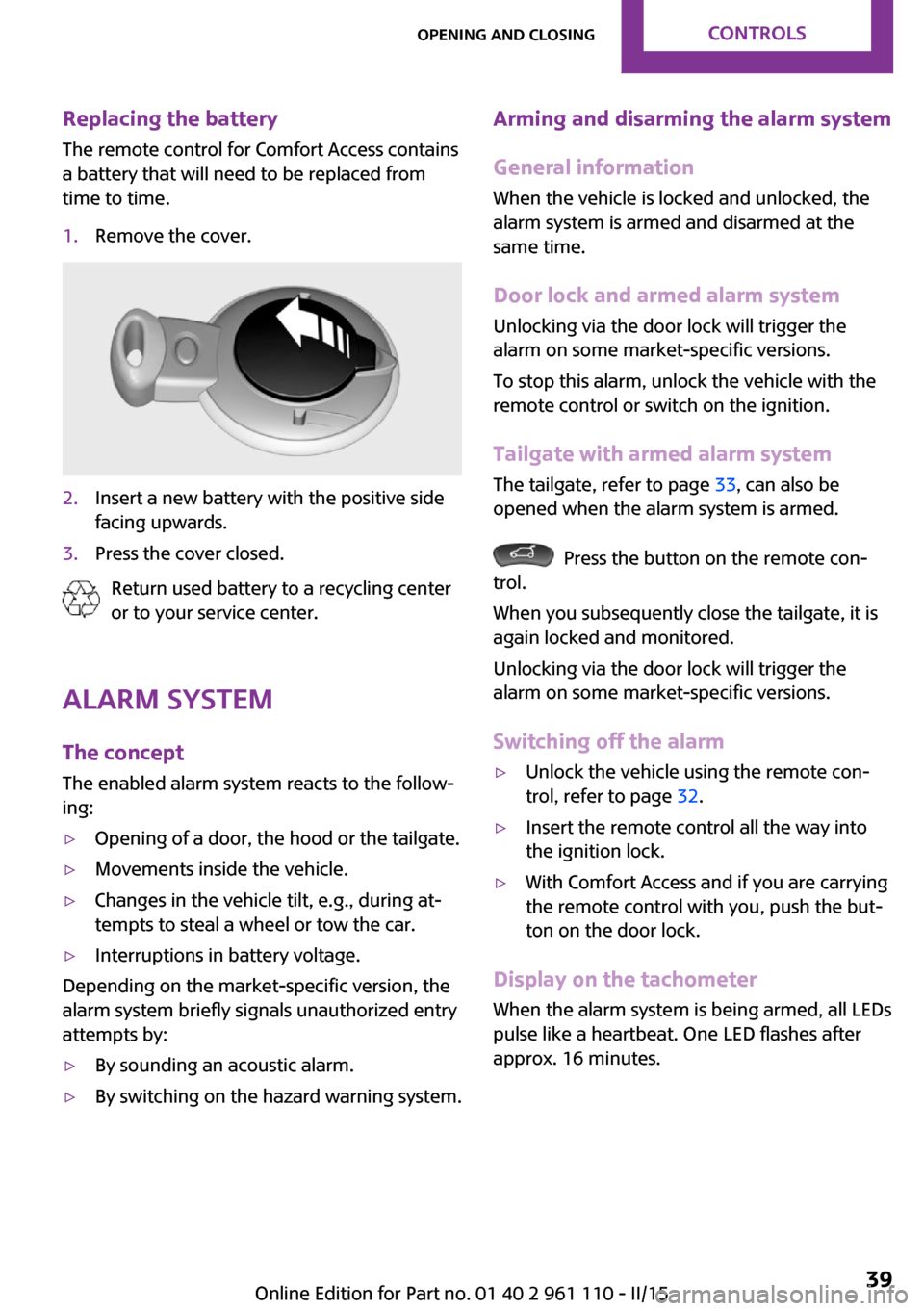
Replacing the battery
The remote control for Comfort Access contains
a battery that will need to be replaced from
time to time.1.Remove the cover.2.Insert a new battery with the positive side
facing upwards.3.Press the cover closed.
Return used battery to a recycling center
or to your service center.
Alarm system
The concept
The enabled alarm system reacts to the follow‐
ing:
▷Opening of a door, the hood or the tailgate.▷Movements inside the vehicle.▷Changes in the vehicle tilt, e.g., during at‐
tempts to steal a wheel or tow the car.▷Interruptions in battery voltage.
Depending on the market-specific version, the
alarm system briefly signals unauthorized entry
attempts by:
▷By sounding an acoustic alarm.▷By switching on the hazard warning system.Arming and disarming the alarm system
General information
When the vehicle is locked and unlocked, the
alarm system is armed and disarmed at the
same time.
Door lock and armed alarm systemUnlocking via the door lock will trigger the
alarm on some market-specific versions.
To stop this alarm, unlock the vehicle with the
remote control or switch on the ignition.
Tailgate with armed alarm system The tailgate, refer to page 33, can also be
opened when the alarm system is armed.
Press the button on the remote con‐
trol.
When you subsequently close the tailgate, it is
again locked and monitored.
Unlocking via the door lock will trigger the
alarm on some market-specific versions.
Switching off the alarm
▷Unlock the vehicle using the remote con‐
trol, refer to page 32.▷Insert the remote control all the way into
the ignition lock.▷With Comfort Access and if you are carrying
the remote control with you, push the but‐
ton on the door lock.
Display on the tachometer
When the alarm system is being armed, all LEDs
pulse like a heartbeat. One LED flashes after
approx. 16 minutes.
Seite 39Opening and closingCONTROLS39
Online Edition for Part no. 01 40 2 961 110 - II/15
Page 60 of 283
Ignition onAll electrical consumers can operate. Most indi‐
cator and warning lights light up for different
lengths of time.
To save battery power when the engine is off,
switch off the ignition and any unnecessary electronic systems/power consumers.
Radio ready state and ignition off All indicator and warning lights in the displays
go out.
The ignition switches off automatically when
the driver's door is opened. Pressing the Start/
Stop button again switches the ignition back
on.
For example, the ignition is not switched off in
the following situations:▷Depress the clutch or brake pedal.▷The low beams are switched on.
Starting the engine
General information Enclosed areas
Do not let the engine run in enclosed
areas; otherwise, breathing of exhaust fumes
may lead to loss of consciousness and death.
The exhaust gases contain carbon monoxide,
an odorless and colorless but highly toxic gas. ◀
Unattended vehicle
Do not leave the car unattended with the
engine running; otherwise, it presents a poten‐
tial source of danger.
Before leaving the car with the engine running,
shift to neutral or engage transmission posi‐
tion P and set the parking brake firmly; other‐ wise, the vehicle may begin to roll. ◀
Frequent starting in quick succession
Avoid repeated futile attempts at starting
the car and avoid starting the car frequently in
quick succession. Otherwise, the fuel is not
burned or is inadequately burned, and there is
the danger of overheating and damaging the
catalytic converter. ◀
Do not wait for the engine to warm-up while
the vehicle remains stationary; start driving
right away, but at moderate engine speeds.
Do not depress the accelerator when starting
the engine.
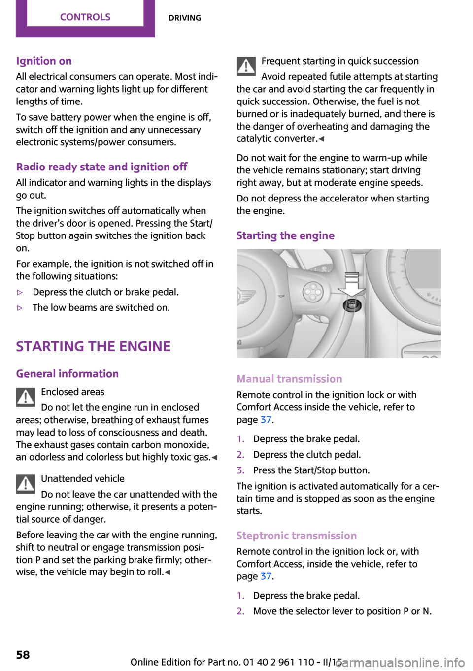
Starting the engine
Manual transmission
Remote control in the ignition lock or with
Comfort Access inside the vehicle, refer to
page 37.
1.Depress the brake pedal.2.Depress the clutch pedal.3.Press the Start/Stop button.
The ignition is activated automatically for a cer‐
tain time and is stopped as soon as the engine
starts.
Steptronic transmission
Remote control in the ignition lock or, with
Comfort Access, inside the vehicle, refer to
page 37.
1.Depress the brake pedal.2.Move the selector lever to position P or N.Seite 58CONTROLSDriving58
Online Edition for Part no. 01 40 2 961 110 - II/15
Page 69 of 283

DisplaysVehicle equipment
This chapter describes all series equipment as
well as country-specific and special equipment
offered for this model series. Therefore, it also
describes equipment that may not be found in
your vehicle, for instance due to the selected
special equipment or the country version. This
also applies to safety-related functions and sys‐
tems.
When using the features and systems described
here, adhere to local regulations.
Odometer, external tem‐
perature display, clock
At a glance1Current speed2Odometer, trip odometer, external temper‐
ature, time3Resetting the trip odometer
Press the button on the turn indicator lever to
open information in display area 2.
The following information is displayed consecu‐
tively:
▷Trip odometer▷Time▷External temperatureTrip odometer
Displaying the trip odometer Press button 3 briefly.
Resetting the trip odometer1.Press button 3 briefly.
The trip odometer is displayed.2.Press button 3 again.
The trip odometer is reset.
Time
Set the time, refer to page 71.
External temperature, external
temperature warning
If the display drops to +37 ℉/+3 ℃, a signal
sounds and a warning light lights up. There is
the increased danger of ice.
Ice on roads
Even at temperatures above
+37 ℉/+3 ℃, there can be a risk of ice on
roads.
Therefore, drive carefully on bridges and shady
roads, for example, to avoid the increased dan‐
ger of an accident. ◀
Units of measure To set the respective units of measure, miles or
km for the odometer and ℃ or ℉ for the exter‐
nal temperature, refer to page 71.
Seite 67DisplaysCONTROLS67
Online Edition for Part no. 01 40 2 961 110 - II/15