light MINI Hardtop 2 Door 2002 Owner's Guide
[x] Cancel search | Manufacturer: MINI, Model Year: 2002, Model line: Hardtop 2 Door, Model: MINI Hardtop 2 Door 2002Pages: 140, PDF Size: 1.63 MB
Page 64 of 140

62
FLAT TIRE MONITORThe conceptThe tire inflation pressure is determined
from the signals of the ABS sensors.
The system provides an alert whenever the
tire inflation pressure drops below the
pressure in any other tire. RequirementSo that the system can "familiarize" itself
with the correct inflation pressure, please
do the following:
1. Check the tire inflation pressure in all
tires
2. Compare them with the inflation pres-
sure table, see page 81, and adjust the
pressures if necessary
3. Initialize the system.
Check the tire inflation pressure
regularly and correct it if necessary,
see page 80.<
Flat tire
The indicator lamp in the instru-
ment cluster informs you by
flashing when the tire inflation
pressure of a tire drops in relation to any
other tire. In addition, an acoustic signal is
sounded.
>Vehicles with safety (run-flat) tires, see
notes on pages 110, 80, 84
>Vehicles with normal tires, see notes on
pages 106, 80.
The Flat Tire Monitor cannot alert you
to severe and sudden tire damage
caused by external factors. Another factor
which the Flat Tire Monitor does not recog-
nize is the balanced and very gradual pres-
sure loss that takes place in all tires over an
extended period of time.<
MalfunctionsAs long as there is still a malfunction, the
yellow indicator lamp on the instrument
cluster will stay lit up.
The indicator lamp also lights up in the
event of a system malfunction.
Please contact your MINI center in these
cases.
Initializing the systemOnly initialize the system if the inflation
pressure, e. g. after a tire change, has been
corrected.
1. Ignition key in position 2
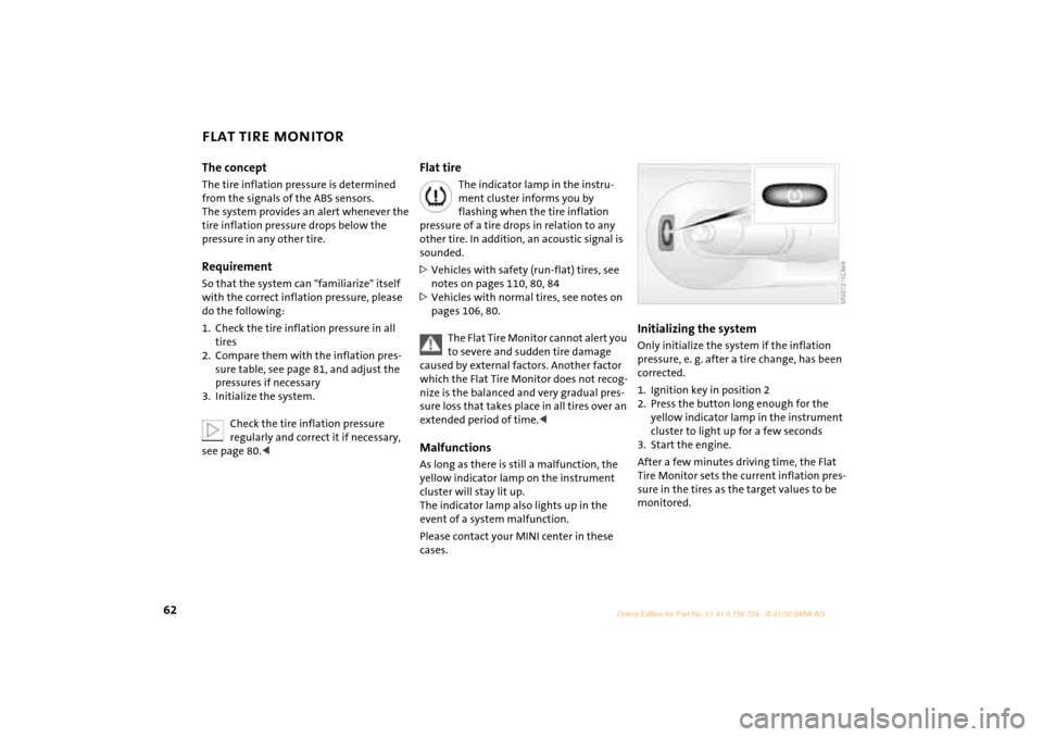
2. Press the button long enough for the
yellow indicator lamp in the instrument
cluster to light up for a few seconds
3. Start the engine.
After a few minutes driving time, the Flat
Tire Monitor sets the current inflation pres-
sure in the tires as the target values to be
monitored.
Page 65 of 140

63
OVERVIEW REPAIRS OPERATIONCONTROLS DATA INDEX
FLAT TIRE MONITOR PARK DISTANCE CONTROL (PDC)*
Do not initialize the system when
snow chains are fitted. When driving
with snow chains, false alarms can occur or
pressure losses might not be detected.<
In the following situations false
alarms can also occur under certain
circumstances or the detection of inflation
pressure loss can be delayed:
>When driving on roads covered with
snow or on other slippery road surfaces
>A sporty driving style (slip at the driven
wheels, high lateral accelerations).<
The conceptThe PDC assists you when you back into a
parking space. A signal warns you of the
distance to an obstacle. To do this, four
ultrasonic sensors in the rear bumper
measure the distance to the nearest object.
The range for the sensors located at both
rear corners ends approx. 2 ft (60 cm)
behind the bumpers. The range for the two
middle sensors is slightly less than 5 ft
(1.5 meters).
The system starts to operate automatically
about one second after you select reverse
with the ignition key in position 2. PDC is
deactivated when you shift back out of
reverse. Acoustical signalsThe distance to the nearest object is indi-
cated by a tone sounding at various inter-
vals. As the distance between vehicle and
object decreases, the intervals between the
tones become shorter. A continuous tone
indicates the presence of an object less
than 9 in (20 cm) away.
The warning signal is canceled after
approx. three seconds if the distance to the
obstacle remains constant during this time
(if you are moving parallel to a wall, for
instance).System malfunctions will be indicated by
a continuous high-pitched tone when the
system is activated the first time. Please
have your MINI center resolve the problem.
Even with PDC, final responsibility for
estimating the distance between the
vehicle and any obstructions always
remains with the driver. Even when sensors
are involved, there is a blind spot in which
objects cannot be detected. Moreover, the
detection of obstructions can approach the
physical limits of ultrasonic measurement,
as occurs e. g. in the case of thin and
wedge-shaped objects.
Certain sources of sound, such as a loud
radio, could drown out the PDC signal
tone.<
Keep the sensors clean and free of ice
or snow in order to ensure that they
will continue to operate effectively.
Do not apply high pressure spray to the
sensors for a prolonged period of time.
Always maintain a distance of more than
4 in (10 cm).<
Page 67 of 140

65
OVERVIEW REPAIRS OPERATIONCONTROLS DATA INDEX
AIR CONDITIONER SYSTEM Air supply
You can select blower speeds
from 1 to 4. Position 0: blower is
switched off. The button for
recirculated-air mode fully blocks
the supply of air from outside.
Heating and ventilation operate as of posi-
tion 1.
Temperature
Turn to the right (red) to increase
the temperature of the
passenger compartment.
Rapid heating: turn to the
extreme right. Then select a pleasant inte-
rior temperature.
Air distribution
Air distribution in upper body
region , upper body region
and footwell , footwell ,
footwell and windows and
windows .
All intermediate positions are possible, see
illustration and overview on page 64.
Rear window defroster
Rear window defroster switched
on:
Indicator lamp lights up.
As long as the indicator lamp is lit, the
heating operates at high power output
(rapid defrosting).
Indicator lamp goes out.
The heating continues to run with reduced
power output and then switches itself off
automatically.
Windshield heating*
Windshield heating switched on:
Indicator lamp lights up.
As long as the indicator lamp is
lit, the heating operates at high power
output (rapid defrosting).
Indicator lamp goes out.
The heating continues to run with reduced
power output and then switches itself off
automatically.
Air conditioner
Air conditioner operation
switched on:
Indicator lamp lights up.
The air is cooled and dehumidified and Ð
depending on the temperature setting Ð
rewarmed.
After the engine start, the windshield can
fog over briefly.
Condensation forms in the air condi-
tioner system during operation, and
then exits under the vehicle. Traces of
condensed water under the vehicle are
therefore normal.<
Recirculated-air mode
Supply of outside air into the
vehicle is blocked: indicator lamp
lights up.
The air within the vehicle is recirculated.
Do not run the recirculated-air mode
for longer than approx. 30 minutes,
as otherwise the air quality in the interior
will deteriorate.
<< < <
If the windows fog over in the recir-
culated-air mode, switch the recircu-
lated-air mode off and increase the air
supply as required.
<< < <
Page 70 of 140

68
AUTOMATIC CLIMATE CONTROL
*
Automatic air distribution and supply
Automatic program (AUTO):
Indicator lamp lights up.
Automatic adjustment of the air distribu-
tion and the air supply and adaptation of
the specified temperatures to external
influences (outside temperature and
sunlight).
In the automatic program (AUTO), the air
conditioner is activated automatically.
Switching the automatic climate
control on/off
The blower, heating and air condi-
tioner are switched off.
To switch the automatic climate control on
again:
Press any button of the automatic climate
control.
Air conditioner
Air conditioner switched on:
Indicator lamp lights up.
The air is cooled and dehumidified and Ð
depending on the temperature setting Ð
rewarmed.
In the automatic program (AUTO), the air
conditioner is activated automatically.
After the engine start, the windshield can
fog over briefly. Switching on the air condi-
tioner reduces condensation on the
windows.
Condensation forms in the air condi-
tioner system during operation, and
then exits under the vehicle. Traces of
condensed water under the vehicle are
therefore normal.
vehicle is blocked:
Indicator lamp lights up.
The air within the vehicle is recirculated.
In the automatic program (AUTO) in hot
weather conditions, the recirculated-air
mode is activated temporarily to enable
faster cooling.
Do not run the recirculated-air mode
for longer than approx. 30 minutes,
as otherwise the air quality in the interior
will deteriorate.<
If the windows fog over in the recir-
culated-air mode, switch the recircu-
lated-air mode off and increase the air
supply as required.<
Rear window defroster and windshield
heating*
Rear window defroster and wind-
shield heating switched on:
Indicator lamp lights up.
As long as the indicator lamp is lit, the
heating operates at high power output
(rapid defrosting).
Indicator lamp goes out.
The heating continues to run with reduced
power output and then switches itself off
automatically.
Temperature
Setting the temperature:
Move or turn the wheel in the
appropriate direction to increase
the temperature step by step.
The figures in the display provide a general
indication of interior temperature. When
you start the vehicle, the system ensures
that the selected temperature is achieved
as quickly as possible and then maintained.
Permanent heating with maximum
power output at temperature selec-
tion "HI". Permanent cooling at "LO".<
Page 72 of 140

70
GLOVE COMPARTMENT ASHTRAY/BEVERAGE HOLDER CIGARETTE LIGHTERTo open:
Pull the handle.
The light goes on.
To close:
Fold the door up.
To prevent injury in the event of an
accident, close the glove compart-
ment immediately after use.<
AshtrayThe ashtray is located in one of the
beverage holders in the center console.
In the rear, an ashtray can also be fitted in
the beverage holder at the end of the
center console. Beverage holdersThere are two beverage holders at the front
of the center console. Another is located at
the end of the center console.
From ignition key position 1:
Press the cigarette lighter in.
Remove as soon as the lighter jumps back
out.
Hold or touch the hot cigarette
lighter by the knob only. Holding or
touching it in other areas could result in
burns.
a rating of approx. 200 Watts at 12 Volts.
Avoid damaging the socket with plugs of
different shapes or sizes.
Page 74 of 140

72
LOADING CARGOStowing cargo >Load heavy cargo as far forward as
possible Ð directly behind the backrests Ð
and as low as possible
>Cover sharp edges and corners
>Do not pile objects higher than the top
edge of the backrest
>For very heavy loads when the rear seat
is not occupied, secure each safety belt in
the opposite buckle. This provides addi-
tional stabilization for the rear backrests.
Securing the load >For small, light items, secure using the
luggage compartment net
* or elastic
straps
>For large, heavy items, see your MINI
center for load-securing devices
*.
Lashing eyes are provided at the inner
corners of the luggage compartment for
attaching these load-securing devices
>Comply with the information enclosed
with the load-securing devices.
Page 78 of 140

76
BREAK-IN PROCEDURES GENERAL DRIVING NOTES To ensure that your vehicle provides
maximum economy throughout a long
service life, we request that you comply
with the following information: EngineUp to 1,200 miles (2,000 km):
Attempt to constantly vary both vehicle
and engine speed during these initial miles
while remembering to avoid engine speeds
in excess of 4,500 rpm and/or vehicle
speeds of over 95 mph (150 km/h).
Absolutely avoid using the full-throttle or
kickdown position for the accelerator.
Once you have driven 1,200 miles
(2,000 km), both the engine and vehicle
speed can be gradually increased.
You should also comply with these break-in
procedures if the engine has to be replaced
at a later point.
TiresDue to technical factors associated with
their manufacture, tires do not achieve
their full traction potential until after an
initial break-in period. We therefore ask
you to drive with extra care during the first
200 miles (300 km).Brake systemApprox. 300 miles (500 km) must be driven
before the brake pads and rotors achieve
the optimum pad-surface and wear
patterns required for trouble-free opera-
tion and an extended service life.ClutchRoughly 300 miles (500 km) must be driven
before the clutch starts to operate at
optimum efficiency. Remember to engage
the clutch carefully during this initial
period.
Parking the vehicleCondensation forms in the air conditioner
system during operation, and then exits
under the vehicle. Traces of condensed
water under the vehicle are therefore
normal.Brakes
Do not rest your foot on the brake
pedal while driving. Even light but
consistent pedal pressure can lead to high
temperatures, brake wear and possibly
even brake failure.<
Hydroplaning
When driving on wet or slushy roads,
reduce road speed. If you do not, a
wedge of water can form between tires and
road surface. This phenomenon is charac-
terized by a partial or complete loss of
contact between the tires and the road
surface. The ultimate results are loss of
steering and braking control.<
Page 81 of 140

79
OVERVIEW REPAIRSOPERATIONCONTROLS DATA INDEX
BRAKE SYSTEMBrake fluid level If the brake fluid level is too low and brake
pedal travel has become longer, there may
be a defect in one of the brake system's
hydraulic circuits.
Proceed to the nearest MINI center.
Higher brake application pressure
may be necessary under these conditions,
there may be slight "pull" to one side, and
brake pedal travel may be longer. Please
remember to adapt your driving style
accordingly.
vehicle is not used at all, and in operating
conditions where brake applications are
less frequent, there is an increased
tendency for corrosion of the brake rotors
and accumulation of contamination on the
brake pads. This occurs because the
minimal pressure that must be exerted by
the pads to clean the rotors by brake appli-
cations is not reached.
Corrosion on brake rotors is signaled by a
running or pulsation during braking; even
extended subsequent braking will not cure
this phenomenon.
It is a good idea to periodically dry the
brakes with a gentle application when
driving in rain and on wet roads.
Monitor traffic conditions to ensure that
this maneuver does not endanger other
road users. The heat generated in this
process helps dry the brake pads and rotors
to ensure that your brake system will
respond with undiminished efficiency
when you need it.
Extended or steep mountain descents
should be driven in the gear or in the
driving position in which only minimal peri-
odic brake application is required. This
helps avoid placing excessive loads on the
brake system. Stay within the allowable
speed range, refer to page 55.
Do not coast with the clutch pressed
or with the transmission or selector
lever in Neutral. Do not coast with the
engine switched off. The engine provides
no braking effect when the transmisson is
in neutral and there is no power-assist for
braking when the engine is switched off.<
Brake pads
For your own safety: use only brake
pads that the manufacturer has
released for your particular vehicle model.
The manufacturer cannot evaluate non-
approved brake pads to determine if they
are suited for use, and therefore cannot
ensure the operating safety of the vehicle
if they are installed.<
Page 86 of 140

84
TIRE REPLACEMENT WHEEL AND TIRE COMBINATIONS Tire age The date on which the tire was manufac-
tured is indicated by the code on the side-
wall:
DOT ... 1202 indicates that the tire was
manufactured in Week 12 of the year 2002.
The manufacturer of your MINI recom-
mends replacement of all tires Ð including
the space-saver spare tire, after no more
than 6 years. Safety (run-flat) tires*
For replacement, use only safety tires,
as in the event of a flat tire there is no
space-saver spare tire.
You will recognize safety tires by a circular
symbol containing the letters RSC on the
side of the tire, see pages 110, 80.<
The right choiceThe factory-approved normal tires and
safety tires are matched to the vehicle and
have been selected to provide optimum
driving safety and the desired driving
comfort.
Never mount wheels and tires that
have not been specifically approved
by the manufacturer for use on your partic-
ular model. Although other wheels and
tires may theoretically have the same
dimensions, variations in factors such as
manufacturing tolerances can result in
contact between tire and bodywork, ulti-
mately leading to serious accidents. The
manufacturer cannot evaluate non-
approved wheels and tires to determine if
they are suited for use, and therefore
cannot ensure the operating safety of the
vehicle if they are fitted.<
The manufacturer has tested certain tire
brands in each size, categorized them as
safe for use on the road, and approved
them. Contact your MINI center for more
details.
The correct wheel and tire combina-
tion affects various systems that
would otherwise be impaired, e.g. ABS,
ASC+T and DSC.
For this reason, use only tires of the same
manufacture and tread configuration. In
the event of a flat tire, for example,
remount the approved wheel and tire
combination as soon as possible.<
StorageStore tires in a cool, dry place, protecting
them against light whenever possible.
Protect the tires against contact with oil,
grease and fuel.Tire changes between axlesDepending on individual operating condi-
tions, different wear patterns appear on
the front and rear axles. In the interests of
safety and optimized handling characteris-
tics, a change between the axles is not
recommended.
Page 93 of 140

91
OVERVIEW REPAIRSOPERATIONCONTROLS DATA INDEX
COOLANT
Do not add coolant to the cooling
system when the engine is hot.
Escaping coolant can cause burns.
To avoid the possibility of damage later on,
never use anything other than factory-
approved, nitrite and amino-free extended-
duty antifreeze with corrosion inhibitor.
Every MINI center is aware of these.
Antifreeze and anti-corrosion agents are
hazardous to health. Always store these
agents in tightly-closed original containers
kept well away from the reach of children.
Extended-duty antifreeze with corrosion
inhibitor contains the flammable
substance ethylene-glycol. For this reason,
do not spill extended-duty antifreeze with
corrosion inhibitor on hot engine parts. It
could catch fire and cause serious burns.<
Comply with the applicable environ-
mental laws regulating the disposal
of extended-duty antifreeze with corrosion
inhibitor.<
The illustration shows an example of the
coolant tank on the MINI COOPER.Checking coolant level Correct coolant level for cold engine
(approx. 68 7/20 6):
Up to the mark "MAX" of the transparent
expansion tank.
Only open the cap of the expansion
tank when the engine has cooled
down. The needle on the coolant tempera-
ture gauge in the instrument cluster must
be no higher than in the first quarter,
otherwise there is a danger of scalding.<
To add coolantMINI COOPER:
1. Slowly open the cap by turning it with
the tab to allow accumulated pressure
toescape.
2. Pull open the cap completely.
3. If the coolant is low, slowly add coolant
until the correct level is reached Ð do not
overfill.
MINI COOPER S:
1. Open the cap by turning it slightly coun-
terclockwise to allow accumulated pres-
sure to escape.
2. Unscrew the cap completely and open.
3. If the coolant is low, slowly add coolant
until the correct level is reached Ð do not
overfill.
The coolant consists of water and
extended-duty antifreeze with corrosion
inhibitor. The mixing ratio of 50 to 50 must
be maintained all the year round due to the
required corrosion resistance. No other
additives are required.
Replace the coolant every 4 years.